Abstract
In this paper, we propose a joint power allocation, time switching (TS) factor and relay selection scheme for an energy harvesting two-way relaying communication network (TWRN), where two transceivers exchange information with the help of a wireless-powered relay. By exploiting the TS architecture at the relay node, the relay node needs to use additional time slots for energy transmission, reducing the transmission rate. Thus, we propose a joint resource allocation algorithm to maximize the max-min bidirectional instantaneous information rate. To solve the original non-convex optimization problem, the objective function is decomposed into three sub-problems and solved sequentially. The closed-form solution of the transmit power of two sources and the optimal TS factor can be obtained by the information rate balancing technology and the proposed time allocation scheme, respectively. At last, the optimal relay node can be obtained. Simulation results show that the performance of the proposed algorithm is better than the traditional schemes and power-splitting (PS) scheme.
1. Introduction
Recently, cooperative communication has become an effective method to achieve spatial diversity by establishing a virtual multi-antenna structure. In a cooperative communication system, relay is used to assist the communication from the source node to its far-end destination node. Due to the communication nodes operated at a half-duplex mode, the information exchanging between two nodes in the one-way relaying network requires four time slots. Thanks to the physical network coding technology, two-way relaying network (TWRN) can complete the bidirectional information transmission in two phases, which effectively mitigates the loss of spectral efficiency [1,2,3].
Although cooperative communication has many advantages, the node power constraint is still a tricky problem. Since relay nodes are always placed in harsh or dangerous places, recharging or replacing batteries of relay nodes may be inconvenient and can incur a high cost [4]. Energy harvesting technology has recently emerged as a promising approach to prolong the lifetime of energy-constrained wireless network from ambient energy, such as wind, solar, etc. However, the received energy at nodes is random and intermittent, which motivates an upsurge of research interest on radio frequency (RF)-based simultaneously wireless information and power transfer [5,6,7]. For RF energy harvesting relay nodes, there are two major energy harvesting relay protocols, which are named as “time switching relay (TSR) protocol” and “power splitting relay (PSR) protocol”. For the TSR protocol, the receiver switches two statuses between information decoding and energy harvesting. For the PSR protocol, the receiver splits the signal into two streams of a different power for providing the transmission power and decoding information separately to complete the whole transmission. In one study [8], a dynamic PS scheme was proposed to split the received signal with adjustable power levels based on the instantaneous channel condition, which could obtain the optimal PS rule at the receiver to achieve various trade-offs between the maximum ergodic capacity and the maximum average harvested energy. For another performance standard, outage probability was investigated in PSR asymmetric two-way relay system [9]. In addition, the system outage performance was studied when the channel state information was imperfect [10]. Additionally, a multi-relay cooperation system could be used to improve the sum rate with PSR protocol [11]. Thus, some paper propose that PSR theoretically achieves better performance [12]. However, PS requires appropriate power split circuits to decide how much of the signal is harvested as energy and how much of it is used for extracting information. This in turn, increases the complexity/cost of the hardware. On the other hand, hardware non-idealities can significantly reduce the efficiency of PS technology [13]. Therefore, TS can be widely investigated due to its low implementation complexity [14,15]. In another study [16], the throughput of the TSR one-way relay system was investigated. In this paper, we employ the TS protocol in TWRN.
The TSR relay nodes need to use additional time slots for energy transmission, which will reduce the performance of the system. Relay selection and power allocation are two effective ways to improve system performance in the TWRN. Traditional relay selection scheme is based on the channel status information between the relay and the user [17]. In one study [18], Bayes theorem was applied in the relay selection scheme, which improved the throughput significantly. Combining power allocation, the algorithm in another study [19] selected the relay with minimum symbols error probabilities as the cooperative relay and obtained the closed-form expression of the power. In one finding [20], a joint relay selection and power allocation for TWRN was proposed to maximize the smaller of the received SNRs of the two transceivers under the total transmitted power budget. Also, the two novel power allocation schemes have been found to maximize the upper bound of sum rate and could achieve the trade-off of outage probability between two terminals [21]. For maximizing the energy efficiency, the optimal power allocation and relay selection scheme can be obtained [22]. In [23], the power allocation and relay selection algorithm is designed by energy pricing in the decode-and-forward cooperative network. Due to the introduction of energy harvesting technology, the traditional power allocation and relay selection algorithms will no longer be applicable for novel systems. Therefore, this paper proposed a joint power allocation and relay selection algorithm for the TSR relay network.
In this paper, we consider an AF-based two-way relay network with energy harvesting technology, where two sources exchange information by the TSR energy harvesting relay node. We first combine the TSR protocol with the two-way relaying system and propose an optimal power allocation and relay selection scheme, which aims to maximize max-min bidirectional instantaneous information rate. The closed-form expressions of the optimal power with the fixed TS factor and the fixed relay node can be obtained when the bidirectional link information rate is equal. Then, a time allocation scheme is used to obtain the optimal TS factor, which can maximize information rate with the optimal transmit power and the fixed relay node. Lastly, the optimal relay can be obtained with the optimal transmit power and TS factor. Simulation results show that the proposed power allocation and relay selection scheme outperforms the traditional method and the PS scheme.
The rest of paper is organized as follows. Section 2 introduces the system model of the TSR energy harvesting two-way relaying network. Section 3 presents a joint power allocation, relay selection and TS factor optimization scheme. In Section 4, numerical results verify the better performance of the proposed scheme compared with traditional algorithms. Finally, Section 5 concludes this paper.
2. System Model
The considered system model and the TS architecture are shown in Figure 1. One source wants to transfer its own information to a far-end source. Due to the long-distance information transmission, two sources cannot communication directly. Thus, two sources use the selected TS relay node to transmit information and the system model can be abstracted as Figure 1. The abstracted system model consists of two source nodes and a set of relay nodes (). The relay nodes are merely powered through wireless energy transfer from two sources and all relay nodes adopt amplify-and-forward mode. There is no direct link between the two source nodes and due to deep fading. Each node is equipped with a single antenna and operated in a half-duplex mode. and are donated as the instantaneous channel gains between to (or to ) and to (or to ), respectively. and are assumed to be independent and distributed complex Gaussian random variables (CGRVs) with zero-mean and variances and . According to TSR protocol, the relay node uses a switch-like structure to acquire energy or signals in two time phases. Thus, the whole transmission block is divided into , and , where is donated as TS factor. part is called energy harvesting phase, part is called multiple-access phase, and the remainder part is called broadcast phase, as shown in Figure 2.
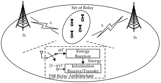
Figure 1.
Illustration of a two-way AF relay system and the TS relay architecture.

Figure 2.
TSR protocol at the energy harvesting relay.
In the energy harvesting phase, the relay nodes receive the energy signal from two source nodes and through RF transmission. The signal received by the relay nodes can be written as
where the parameters and are the transmit power from two sources, and the parameter is the additive noise. Since the energy of the noise signal is negligible as compared to that harvested energy from the RF signal [16], the harvested energy at relay node can be written as
where the parameter is the conversion efficiency of the energy receiver and is the TS factor. Then, the received energy is used for the broadcast phase, and we can describe the relay transmit power as
In multiple-access phase, and transmit the information signal and simultaneously to the selected th relay (), so the received signal at the relay node can be denoted as
In the broadcast phase, the th relay node amplifies the received signal then broadcasts it to two source nodes and . The received signal at and can be presented as
where the parameters and follow and , respectively. The parameter is denoted as the amplifying gain at the relay node, which can be considered by normalization of the received signal, i.e.,
Substituting (4) into (5) and (6), the received signal can be rewritten, respectively,
where and are considered as the self-interference of the two sources. We assume that the total channel state information (CSI) can be obtained at two source nodes and . Thus, the self-interference can be completely eliminated. After self-interference cancellations of the nodes and , (8) and (9) can be rewritten as
3. Joint Optimal Power Allocation and Relay Selection Scheme
In this section, we propose a joint optimal power allocation, TS factor and relay selection scheme for wireless-powered TWRN that maximizes the smaller of the bidirectional instantaneous information rate under some constraint conditions. As mentioned in [20], the performance of TWRN is mainly affected by the worse instantaneous information rate between and . Therefore, the proposed scheme first optimizes the transmit power. Then the optimal TS factor can be obtained with the optimal power allocation. At last, we select the optimal relay with the maximum instantaneous information rate in the set. Applying (10) and (11), the instantaneous signal-to-noise-ratio (SNR) at two source nodes and can be described as
Since the information is only transmitted within time and all nodes operated in a half-duplex mode, the instantaneous information rate from to and the instantaneous information rate from to are given by
Therefore, the optimization function of the proposed scheme can be expressed as
where is the total transmit power and . In order to remove the minimized symbol, the original optimization problem can be converted as
To obtain the optimal solution of (17), we divide the optimization problem (17) into three parts. First, we perform an optimal power allocation in the case of the fixed TS factor and the fixed relay node. Second, we perform an optimal TS factor with the optimal power allocation and fixed relay node. Last, we perform an optimal relay selection with the optimal power allocation and the optimal TS factor.
For the fixed TS factor and the fixed relay node, the optimization problem can be described as
Lemma 1.
The optimization problem (18) is optimal when, i.e.,.
Proof of Lemma 1.
The total power constraint can be rewritten as and . It is easy to know that and are the monotonically increasing function and the monotonic decreasing function with respect of , respectively. Also, the objection function is to select the smaller instantaneous information rate of two links. Thus, the optimal power allocation can be obtained when . □
According to Lemma 1, we obtain that
For simple calculation but without loss of generality, we assume . The Equation (19) can be rewritten as
Then, applying (20) into (18), the optimization problem (18) can be written as
For the objective function (21), is a monotonically increasing function with respect to . It is easy to get the optimal power value when . And combined with Equation (20), the optimal transmit power of two sources are given by
For optimal power allocation and fixed relay node, the optimization problem can be written as
Lemma 2.
is a concave function about with the range of 0 to 1.
Proof of Lemma 2.
We first solve the first derivative of the function with respect of the TS factor .
where and . The second order derivative of with respect to is given by
Since and TS factor exists in , we can obtain that . Thus, there is a optimal value that maximizes .
Lemma 2 is proved. □
According to Lemma 2, the original optimization problem with respect to is a strictly concave function. Note that when and when . Obviously, there exists an optimal TS factor in . However, it is difficult to obtain the closed-form expression of optimal since the first-order derivative of is so complicated and there exist a large amount of unknown. Therefore, the following time allocation scheme is proposed to get the optimal value of when .
| Time allocation scheme |
| 1: Initialization: setting the value , , is a positive real number close to 0; 2: While do 3: Based on , calculate , where ; 4: If , set and go to 9; |
| 5: Else if , set ; 6: Else if , set ; 7: end if 8: End while 9: is the optimal solution. |
For optimal power allocation and optimal TS factor, the original problem in (16) is reduced to the following relay selection problem:
The optimal relay selection method can be described by selecting the cooperative relay with the maximum instantaneous information rate in relays.
The original max-min bidirectional instantaneous information rate can be solved by the proposed joint optimal power allocation and relay selection algorithm.
| Joint Optimal Power Allocation and Relay Selection |
| 1: Initialization parameters; 2: Obtain and for fixed and fixed relay node following the procedure in Equations (18)–(23); 3: Obtain the optimal for optimal , and fixed relay node using the time allocation scheme; 4: Obtain the optimal cooperative relay node using the traversal method for optimal , and optimal TS factor in relays; |
| 5: end. |
4. Simulation Results and Analysis
In this section, simulation results are performed to present the performance of the proposed power allocation and relay selection scheme. We assume that there are 10 relays in the set and the energy conversion efficiency is . Moreover, the distance between and is normalized to unit value, and the distance between to is expressed as . According to the reference [20], the information rate of TWRN is largest when the relay node is located on the midpoint between and . Therefore, we assume that . Thus, the channel strength of the two channels are and , where is the path loss exponent. In this paper, is set to 2.5. In addition, two source nodes and the relay node have the same noise variance . The SNR can be expressed as . To the Monte Carlo experiment, the simulation results are averaged over 1000 independent channel realizations. Simulation parameters are elaborated in Table 1.

Table 1.
Simulation parameters.
Figure 3 depicts the information rate curves of using different SNRs under various TS factor . It can be observed that these curves have the same tendency under the different total transmit power constraints. From the trend, the three curves are concave, which demonstrate the accuracy of the analysis in Section 3. As can be seen from Figure 3, the system information rate can achieve 2.67 bps/HZ when the total transmitted power is 15 dB. When the total transmitted power is 20 dB, the system information rate can achieve 3.387 bps/HZ. When the total transmitted power is 25 dB, the system information rate can achieve 4.2 bps/HZ. We note that the optimal TS factor can be found in the range (0, 1).
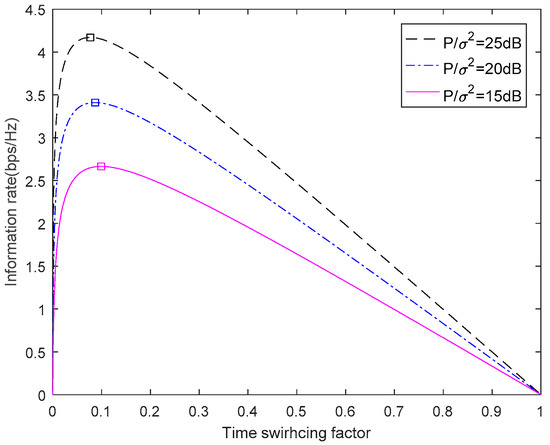
Figure 3.
The information rate versus TS factor.
The information rate versus SNRin three different schemes is showen in Figure 4. The three schemes are the proposed scheme, the joint resource allocation PS scheme and equal power allocation PS scheme. For the joint resource allocation PS scheme, the power allocation scheme is based on the end-to-end SNRs balancing criterion. The instantaneous SNRs at two source nodes can be formulated as
where is the PS factor and it is fixed as 0.5. The max-min bidirectional information rate has the maximum when . Therefore, the optimal power allocation scheme under the total power constraint can be expressed as
Then, we select the cooperative relay node from the relay set, which can maximize the information rate. For the equal power allocation scheme, two source nodes have equal transmission power and the relay selection is random. As shown in Figure 4, the performance of the proposed scheme is better than the other two PS schemes where the SNR ranges from 0 dB to 20 dB. That is because the PS factor is fixed and the cooperative relay is chosen randomly while the proposed scheme has the optimal TS factor, the optimal cooperative relay and the optimal power allocation.
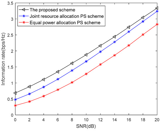
Figure 4.
The proposed scheme versus the PS scheme.
Figure 5 shows the information rate of our proposed scheme under four different cases. The fix TS factor is set as . Case 1 is the proposed algorithm that has the optimal relay, the optimal power allocation and the optimal TS factor, which is called O-PA&O-RS&O-TS. The optimal relay, the optimal power allocation and the fixed TS factor is called O-PA&O-RS&F-TS as case 2. Case 3 is the optimal relay, the equal power allocation and the fixed TS factor, which is called E-PA&O-RS&F-TS. Case 4 is the random relay, the equal power allocation and the fixed TS factor, which is called E-PA&R-RS&F-TS. From Figure 5, we note that the optimal relay selection has a great impact on the information rate by comparing case 3 and case 4. However, the information rate of case 2 and case 3 are very similar, for the system only allocates power to two source nodes, and the channels are distributed and independent. As shown in Figure 5, case 4 has the worst performance in four algorithms. The performance of case 2 and case 3 are improved compared with case 4, while the proposed algorithm has the best performance. The information rate of the proposed scheme is about 1.4 bps/HZ higher than case 2 and case 3 when SNR = 20 dB.
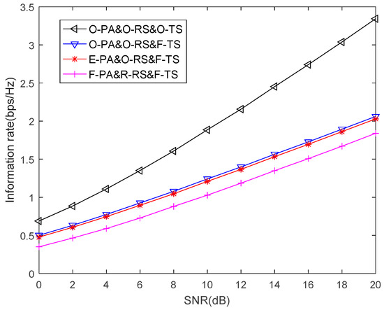
Figure 5.
Performance of TS scheme in different power allocation and relay selection methods.
Figure 6 displays the information rate versus SNR by comparing the proposed scheme, joint power allocation and relay selection in [20] and the traditional equal power allocation (EPA) scheme. From reference [20], the optimal values of , and can be obtained as
With the optimal power allocation solution found, selecting the relay node with maximum SNR as cooperative relay. The traditional EPA scheme is defined as and the relay selection is random. From Figure 6, it can be seen that the proposed scheme has better performance than the other two schemes. And compared with the other two schemes, the relay node can harvest energy through wireless–powered, which solve the power constraint of relay nodes.
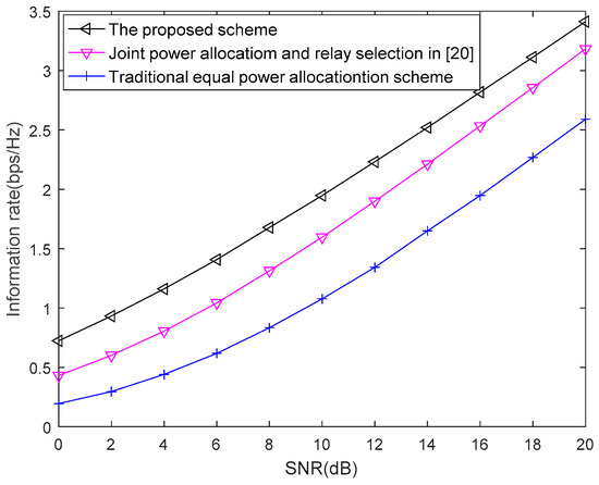
Figure 6.
Performance comparison between the proposed scheme and the conventional scheme.
As shown in Figure 7, the number of relay nodes in the relay set has an impact on the information rate. The proposed algorithm has the lowest information rate when . As the number of relays increases, the information rate increases. When the number of relays reaches 100, the information rate can reach 3.49 bps/HZ. The improvement of the information rate can reach 0.1 bps/HZ when the relay numbers from 10 to 50. However, the improvement of the information rate is only about 0.02 bps/HZ when the relay numbers from 50 to 100, which indicates that excessive candidate relays do not significantly improve the information rate. In future research, we can expand the optimal number of candidate relays in this study.
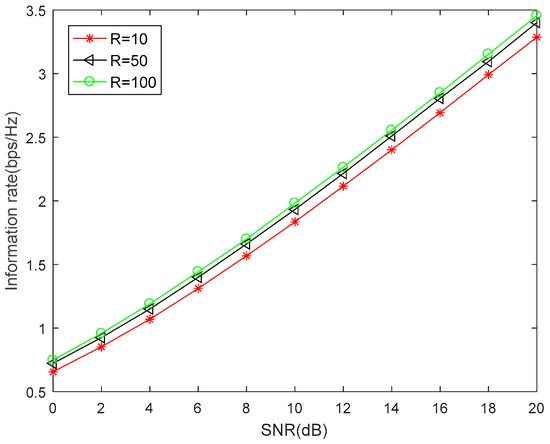
Figure 7.
Information rate versus different relay number in the relay set.
5. Conclusions
In this paper, we propose a joint power allocation and relay selection algorithm based on TS relay architecture, which aims to maximize the max-min bidirectional instantaneous information rate. The system model can be widely applied into the fields of 5G, wireless sensor, internet of things, cognitive radio and wireless body area network. By using the balancing information rate criterion, the closed-form of the optimal power allocation can be obtained. Then, the proposed time allocation scheme can get the optimal TS factor. At last, the relay with the largest instantaneous information rate of the set is selected as the optimal cooperative relay. Energy harvesting technology can solve the energy problem in energy-constrained nodes and reflect the concepts of green environmental protection and sustainable development. The proposed algorithm can make up the loss of the information rate for energy transmission. Simulation results show that the proposed scheme provides effective performance improvement over the traditional schemes. However, energy harvesting technology may cause loss of spectral efficiency. Therefore, combining full-duplex technology will be the direction for future research.
Author Contributions
Conceptualization, S.X.; data curation, S.X.; formal analysis, S.X.; funding acquisition, X.S.; methodology, S.X.; project administration, X.S.; software, S.X.; supervision, X.S.; validation, S.X. and Z.X.; visualization, S.X.; writing—original draft, S.X.; writing—review and editing, X.S., S.X., Z.X. and X.H.
Funding
This work was supported by the National Nature Science Foundation of China under Grant No. 61473066 and No. 61601109, and the Fundamental Research Funds for the Central Universities under Grant No. N152305001.
Acknowledgments
The authors thank the anonymous reviewers for their insightful comments that helped improve the quality of this study.
Conflicts of Interest
The authors declare no conflict of interest.
References
- Popovski, P.; Yomo, H. Physical Network Coding in Two-Way Wireless Relay Channels. In Proceedings of the 2007 IEEE International Conference on communications, Glasgow, UK, 24–28 June 2007; pp. 707–712. [Google Scholar]
- Xie, X.; Peng, M.; Zhao, B.; Wang, W.; Hua, Y. Maximum a Posteriori Based Channel Estimation Strategy for Two-Way Relaying Channels. IEEE Trans. Wirel. Commun. 2014, 13, 450–463. [Google Scholar] [CrossRef]
- Wang, X.; Nan, Y.; Hoang, T.M.; Gulliver, T.A.; Hao, Z. Generalized Selection at Multi-Antenna Sources in Two-Way Relay Networks. IET Commun. 2016, 10, 824–831. [Google Scholar] [CrossRef]
- Zhang, R.; Ho, C.K. MIMO Broadcasting for Simultaneous Wireless Information and Power Transfer. IEEE Trans. Wirel. Commun. 2013, 12, 1989–2001. [Google Scholar] [CrossRef]
- Liu, K.H.; Lin, P. Toward self-sustainable cooperative relays: state of the art and the future. IEEE Commun. Mag. 2015, 53, 56–62. [Google Scholar] [CrossRef]
- Gu, Y.; He, H.C.; Li, Y.; Vucetic, B. Distributed Multi-Relay Selection in Accumulate-Then-Forward Energy Harvesting Relay Networks. IEEE Trans. Green Commun. Netw. 2018, 2, 74–86. [Google Scholar] [CrossRef]
- Ramezani, P.; Jamalipour, A. Toward the Evolution of Wireless Powered Communication Networks for the Future Internet of Things. IEEE Netw. 2017, 31, 62–69. [Google Scholar] [CrossRef]
- Liu, L.; Zhang, R.; Chua, K.C. Wireless Information and Power Transfer: A Dynamic Power Splitting Approach. IEEE Trans. Commun. 2013, 61, 3990–4001. [Google Scholar] [CrossRef]
- Men, J.; Ge, J.; Zhang, C.; Li, J. Joint optimal power allocation and relay selection scheme in energy harvesting asymmetric two-way relaying system. IET Commun. 2015, 9, 1421–1426. [Google Scholar] [CrossRef]
- Zhang, Y.; Ge, J.; Men, J.; Ouyang, F.; Zhang, C. Joint relay selection and power allocation in energy harvesting AF relay systems with ICSI. IET Microwaves Antennas Propag. 2016, 10, 1656–1661. [Google Scholar] [CrossRef]
- Alsharoa, A.; Ghazzai, H.; Kamal, A.E.; Kadri, A. Near Optimal Power Splitting Protocol for Energy Harvesting Based Two Way Multiple Relay Systems. In Proceedings of the Wireless Communications and Networking Conference, San Francisco, CA, USA, 19–22 March 2017. [Google Scholar]
- Lu, X.; Wang, P.; Niyato, D.; Dong, I.K.; Han, Z. Wireless Networks with RF Energy Harvesting: A Contemporary Survey. IEEE Commun. Surv. Tutor. 2017, 17, 757–789. [Google Scholar] [CrossRef]
- Krikidis, I.; Sasaki, S.; Timotheou, S.; Ding, Z. A Low Complexity Antenna Switching for Joint Wireless Information and Energy Transfer in MIMO Relay Channels. IEEE Trans. Commun. 2014, 62, 1577–1587. [Google Scholar] [CrossRef]
- Ni, Z.; Motani, M. Transmission schemes and performance analysis for time-switching energy harvesting receivers. In Proceedings of the 2016 IEEE International Conference on Communications, Kuala Lumpur, Malaysia, 22–27 May 2016. [Google Scholar]
- Ni, Z.; Motani, M. Optimization of time-switching energy harvesting receivers over multiple transmission blocks. In Proceedings of the 2016 IEEE International Symposium on Information Theory, Barcelona, Spain, 10–15 July 2016. [Google Scholar]
- Nasir, A.A.; Zhou, X.; Durrani, S.; Kennedy, R.A. Relaying Protocols for Wireless Energy Harvesting and Information Processing. IEEE Trans. Wirel. Commun. 2012, 12, 3622–3636. [Google Scholar] [CrossRef]
- Bletsas, A.; Khisti, A.; Reed, D.P.; Lippman, A. A simple Cooperative diversity method based on network path selection. IEEE J. Sel. Areas Commun. 2006, 24, 659–672. [Google Scholar] [CrossRef]
- Ferdouse, L.; Anpalagan, A. Relay Selection Based on Bayesian Decision Theory in Cooperative Wireless Networks. Can. J. Electr. Comput. Eng. 2015, 38, 116–124. [Google Scholar] [CrossRef]
- Wang, C.L.; Cho, T.N.; Yang, K.J. On Power Allocation and Relay Selection for a Two-Way Amplify-and-Forward Relaying System. IEEE Trans. Commun. 2013, 61, 3146–3155. [Google Scholar] [CrossRef]
- Talwar, S.; Jing, Y.; Shahbazpanahi, S. Joint Relay Selection and Power Allocation for Two-Way Relay Networks. IEEE Signal Process. Lett. 2010, 18, 91–94. [Google Scholar] [CrossRef]
- Zhang, Y.; Ma, Y.; Tafazolli, R. Power Allocation for Bidirectional AF Relaying over Rayleigh Fading Channels. IEEE Commun. Lett. 2010, 14, 145–147. [Google Scholar] [CrossRef]
- Rong, H.; Feng, C.; Zhang, T.; Wei, W. Energy-efficient relay selection and power allocation scheme in AF relay networks with bidirectional asymmetric traffic. In Proceedings of the 14th International Symposium on Wireless Personal Multimedia Communications, Brest, France, 3–7 October 2011. [Google Scholar]
- Feng, K.; Feng, S.; Zhuang, H. Relay Selection and Power Allocation for Cooperative Network Based on Energy Pricing. IEEE Commun. Lett. 2010, 14, 396–398. [Google Scholar]
© 2019 by the authors. Licensee MDPI, Basel, Switzerland. This article is an open access article distributed under the terms and conditions of the Creative Commons Attribution (CC BY) license (http://creativecommons.org/licenses/by/4.0/).