Abstract
In this paper, we propose an optimal time and power allocation scheme in a wireless power supply full-duplex (FD) relay system, where we consider the number of relay antennas in the energy harvesting stage. At the same time, the energy efficiency optimization problem of the system is structured, where optimization issues related to time allocation factors and power allocation are established. For the FD dual-antenna and the FD single-antenna energy harvesting system, energy efficiency function is proven to be a concave function over the time-switch factor, and the optimal time-switching factor is theoretically obtained using the Lambert function. Then, according to the given value range of the optimal time switching factor, the optimal power distribution scheme is obtained by analyzing the derivative function of the system energy efficiency and using the properties of the Lambert function. The time-switching factor and transmission power are optimally selected at the wireless power supply FD relay. Results reveal that the performance of energy efficiency of the dual-antenna energy harvesting at the FD relay outperforms that of the single-antenna. Moreover, our results demonstrate that FD relay systems always substantially boost the energy efficiency compared with half-duplex (HD) relay systems.
1. Introduction
In some practical scenarios, the traditional energy-limited communication system has a limited operational life. To maintain the continuity and connectivity of energy-limited wireless relay networks, nodes are usually equipped with fixed energy. Traditional battery-powered systems need to be periodically replaced or charged to maintain network connectivity [1,2]. However, in certain situations (such as in vivo sensors), battery charging is inconvenient or impossible, and the life cycle of the wireless network is limited. To solve this problem, proposed energy acquisition schemes are proposed. However, the energy collected from the external environment is random and susceptible to many factors, such as weather and geography, and a continuous, stable energy supply is difficult to provide to the wireless network, making normal communication more difficult. In recent years, because radio-frequency (RF) signals can simultaneously carry information and energy, technology involving the use of RF signals for energy collection has received extensive attention. This technology has the advantages of controllability and measurability, which can be used in wireless systems compared with traditional energy harvesting technologies, thereby providing an effective solution to solve the energy supply problem of energy-constrained nodes in harsh environments.
According to the interaction between wireless energy transmission and wireless information transmission, two main architectures for implementing wireless energy information [3,4] are proposed, namely, power splitting (PS) and time switching (TS). For the TS protocol [5,6], the energy and information signals are transmitted through different time slots. The data source first collects energy from the power signal and then uses the collected energy to transmit the information signal [7]. For the PS architecture [8,9], the receiver divides the received power between energy harvesting and information processing. According to the time (TS) receiver architecture, we propose a closed expression of system throughput based on an adaptive TS protocol, as seen in [10]. In [11], for PS optimization of decode-and-forward (DF) and amplify-and-forward (AF) relays, an efficient algorithm was proposed by using the PS strategy in a simultaneously (SWIPT), multi-relay assisted, dual-hop relay system. In order to make full use of the collected energy, this study analyzes important performance indicators [12,13,14,15,16,17] such as energy efficiency and outage probability. The analytic expressions of ergodic capacity and outage probability based on adaptive TS protocol were deduced in [17]. However, these tasks were only considered with regard to HD mode. Because HD relay transmits and receives signals in different frequency bands, it causes significant loss of spectral efficiency. In order to reduce the loss of spectral efficiency, FD architecture was proposed in [18].
With the latest advances in antenna and signal processing technology, FD relays are considered to be possible [19,20,21,22]. Since the working mode of the relay node changes from HD to FD, the hardware structure also changes, therefore, previous power allocation schemes are not applicable; we expect new resource allocation schemes and transmission protocols to become the main directions in future research. In [23], the authors studied wireless-powered FD relay systems based on a TS protocol, where the number of antennas of relay nodes in the energy harvesting phase was considered and the analytical expressions of throughput maximization in three different communication modes (instantaneous transmission, delay-constrained transmission, and delay-tolerant transmission) were derived by optimizing the TS factor. Moreover, the throughput of the wireless-powered multi-antenna FD relay system was analyzed in [24]. In [25], the author proposed a new optimal power allocation scheme for bidirectional FD relay. By using the optimal PS factor and the transmission beamforming vector of the relay together, the throughput of the wireless-powered FD relay system based on the PS protocol was maximized in [26]. Due to the gradual increase in energy costs and people’s awareness of environmental protection, power efficiency has become an important performance indicator in the field of wireless communication. However, there are few studies on the power efficiency of the wireless-powered FD relay with dual-antenna energy harvesting.
Motivated by the above problems, in this paper, the optimal time allocation and optimal power allocation scheme is proposed to maximize the energy efficiency in the FD relay system. In order to make full use of the hardware resources of the system, this paper analyzes the FD relay in two ways: By using two antennas to receive simultaneously in the energy acquisition phase, by selecting the optimal single-antenna reception in the energy acquisition phase. The energy efficiency maximization of the FD optimal time and the power allocation scheme was compared with that of traditional HD optimal time and power allocation scheme.
The remainder of the paper is organized as follows. In Section 2, the system model of the wireless-powered FD relay system is described and the energy efficiency optimization problem is formulated. In Section 3, the optimal time and power allocation schemes to maximize the energy efficiency of the dual-antenna energy harvesting system are proposed. Section 4 elaborates on the proposed algorithm of the optimal time and power allocation in the FD single-antenna energy harvesting system. In Section 5, the energy efficiency optimization problem for the HD relay systems is introduced. Section 6 analyzes the numerical results, and the last section draws conclusions.
2. System Model and Problem Formulation
In this section, we first establish a system model and then develop an optimal time allocation problem and optimal power allocation problem for energy efficiency maximization of the wireless power communication networks, namely, FD dual-antenna energy harvesting and single-antenna energy harvesting.
2.1. System Model
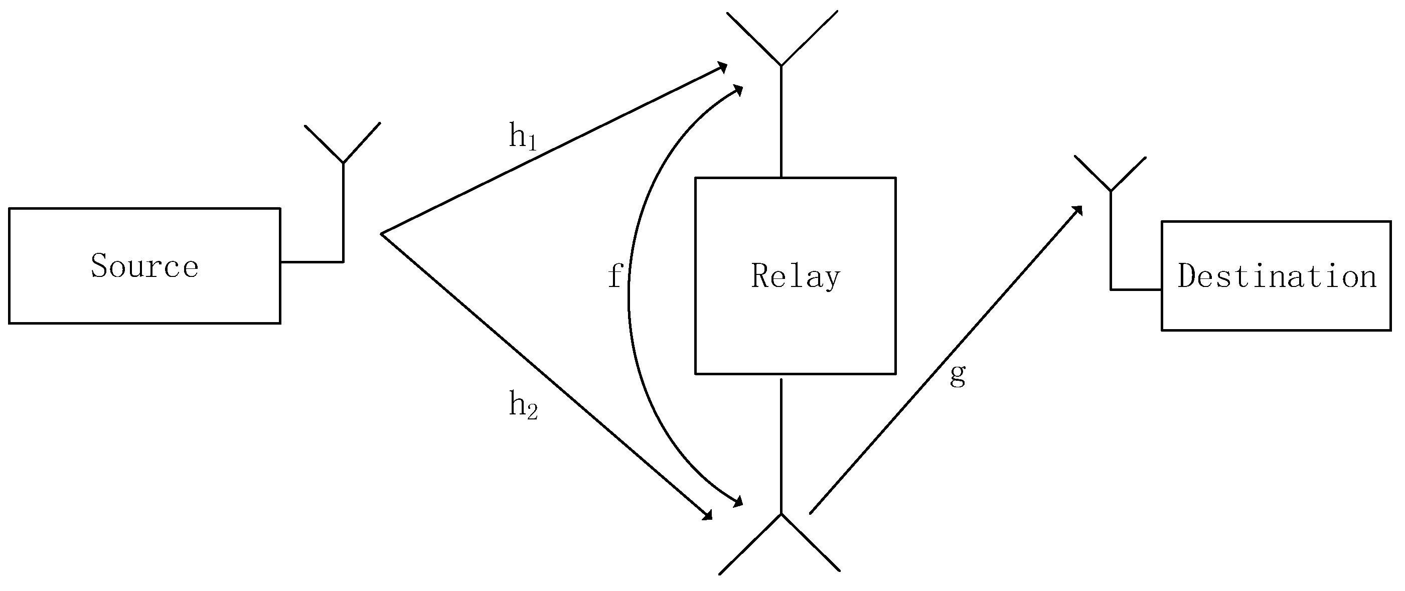
As shown in Figure 1, the full-duplex decoding and forwarding (DF) wireless power communication system consists of a source node S, a relay node R, and a destination node D. In the system, both the source node and the destination node are equipped with one antenna, and the relay node that performs the FD transmission is equipped with two independent antennas, including one antenna for transmission and another for reception. The channel gains from the source node S to the relay node R and R to the destination node D are and , where and are the channel coefficients, respectively. All channels are distributed complex Gaussian channels with zero-mean and unit-variance, i.e., It is assumed that there is no direct link between the source node and the destination node. All channel power gains follow the fixed block fading model. They remain constant during one block, but remain independent for a different block. It is assumed that the relay node is an energy-limit node, and energy acquisition is performed from the source node.
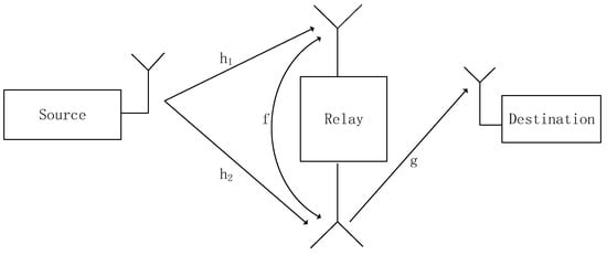
Figure 1.
System model of wireless-powered FD relay systems.
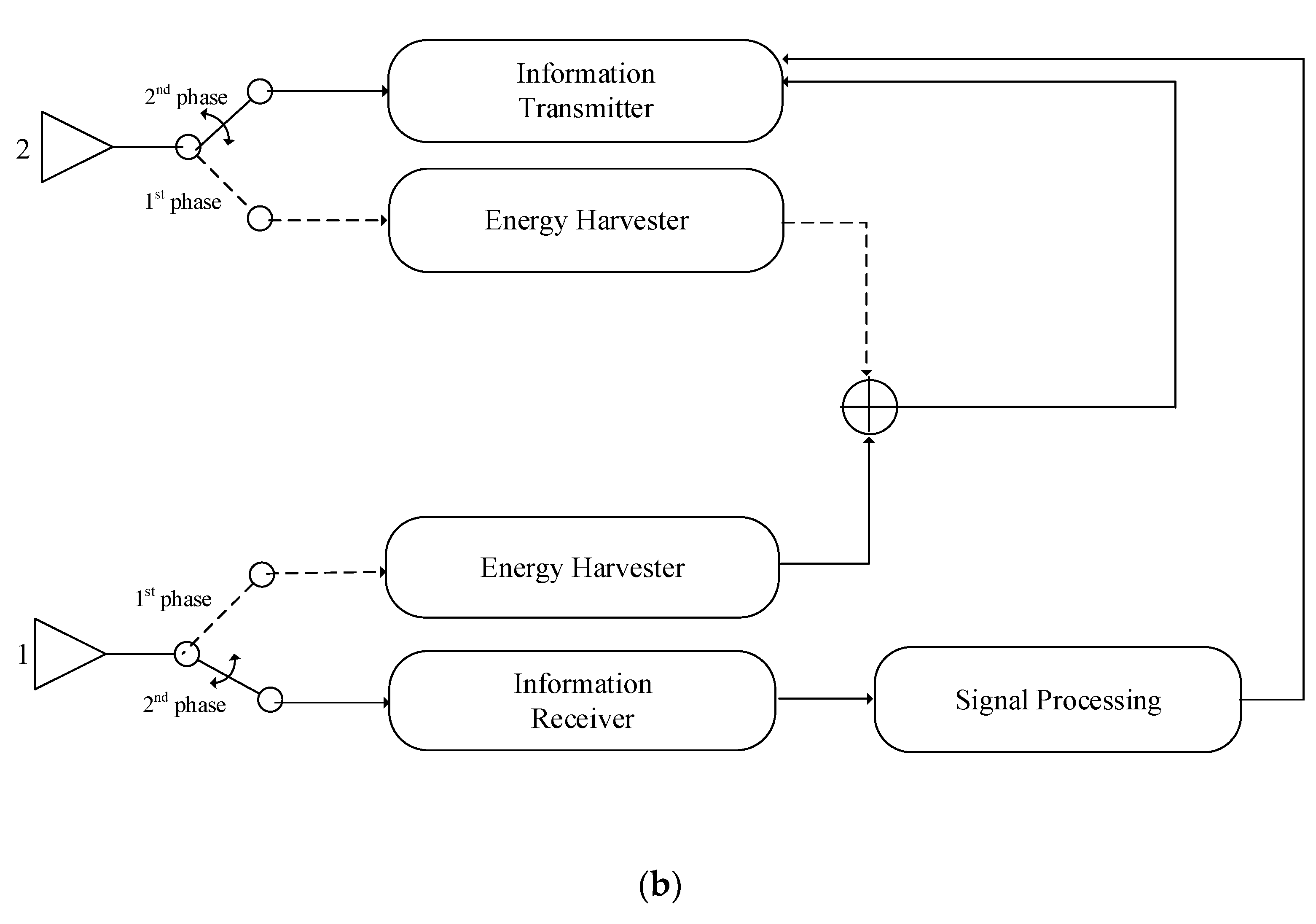
The system uses a time division protocol in Figure 2. The process is divided into two phases, namely, the energy harvesting phase and the information transmission phase. In the first phase, the relay node performs energy acquisition from the source node. In the second phase, the relay node use decoder forwarding to forward signals received from the source node to the destination node.

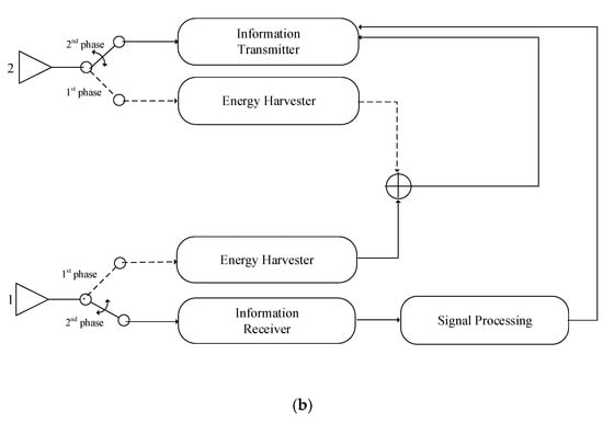
Figure 2.
(a) Two-phase SWIPT protocol. (b) Time-switching architecture at the FD relay.
In order to make full use of FD hardware resources (antenna units) for energy harvesting, we use the time-switch protocol, as shown in Figure 2b, to switch the receiving and transmitting antennas to the energy harvesting circuit in the first stage.
2.2. Full-Duplex Dual-Antenna Energy Harvesting
In the energy harvesting phase, the relay node uses dual antennas for energy harvesting. The received signal of the relay R can be expressed as
where is the transmission power of the source and is the Gaussian white noise of the relay node. The unit power is known to be transmitted to the relay node by the source node. The energy that the relay node obtains from the source node can be expressed as
where is the energy conversion efficiency. As in [27], this depends on the rectification process and the energy harvesting circuit. Here, we do not consider the noise power, which is much smaller than the power of the energy signal [28].
As in [29,30], we assume that the system works in the original architecture used by the collector. The energy collected during the energy harvesting phase is stored in a supercapacitor. Then, in the information transmission phase, the energy collected in the first phase is used when the relay node completely consumes the process of forwarding the source signal. Therefore, the transmission power of the relay node can be expressed as
In the information transmission phase, the signal received by the relay node R can be represented as
where is the information signal transmitted by the source node to the relay node in the second phase, is the self-interference coefficient that satisfies and is the Gaussian white noise at the relay node, which obeys the distribution with a mean of zero and a variance of . Since the relay node can recognize its own signal, it eliminates the interference caused by part of itself [31]. Therefore, after interference cancellation, the signal received by the relay node can be expressed as
The residual self-interference coefficient caused by the imperfect self-interference cancellation is usually considered as the Rayleigh channel [32].
In the second phase, we consider the DF protocol. is written as
where is the delay. The signal received by the destination node can be expressed as
where is the Gaussian white noise at the destination node and is the channel coefficient of the relay node to the destination node.
Therefore, the signal to interference and noise ratio can be expressed as
Therefore, the spectrum efficiency of the system can be expressed as
Therefore, the energy efficiency can be expressed as
where is the constant circuit power consumption, which is independent of information transmission, and is the power amplifier. The objective function is to maximize the system energy efficiency, i.e.,
2.3. Full-Duplex Single-Antenna Energy Harvesting
In the energy harvesting phase, the relay node uses a single antenna for the energy harvesting, and the signal received by the relay node R can be expressed as
The energy received by the relay node R can be expressed as
Therefore, the transmission power of the relay node can be expressed as
In the information transmission phase, the single-antenna energy harvesting system and the dual-antenna energy harvesting system are identical for the relay node regarding the full-duplex information transmission performance, in which one antenna is used to receive signals from the source node and the other is used for decoding. Therefore, signal-to-interference-plus-noise ratio (SINR) can be expressed as follows in regard to the single-antenna energy harvesting system
The objective function of energy efficiency can be expressed as
3. The Full-Duplex Dual Antenna Energy Harvesting
3.1. The Optimal Time Allocation Scheme
The energy efficiency optimization problem is written as
When the source node is equal to the relay node and the relay node to the target node, . The time switch threshold can be calculated as
Therefore, the optimal time allocation scheme to maximize the energy efficiency can be transformed into two processes. For the first case, , the time allocation problem to maximize energy efficiency can be presented as
where .
In order to require the time allocation factor of the maximum energy efficiency, the first derivative of the solution in (19) is
Therefore, we can get the optimal time allocation factor in the range ().
where , is the Lambert function, and is the solution of .
For the second case, we construct the energy efficiency optimization problem
where .
The derivative function of the Equation (27) can be obtained and expressed as
Since is always less than zero in the range , the energy efficiency is a monotonically decreasing function in the range . At , the energy efficiency achieves the maximum value within the range . Therefore, we present both cases as follows.
3.2. The Optimal Power Allocation Scheme
Above, we have proved that when , the optimal time-division factor for maximizing energy efficiency is . When , the optimal segmentation factor for maximizing energy efficiency is . Therefore, when , for any , the optimal segmentation factor for maximizing energy efficiency is . At this time, . When we discuss the optimal power allocation scheme, the objective function can be expressed as
By deriving the function of the system energy efficiency and simplifying it, we get
Since the denominator of Equation (27) is greater than zero, the molecule is not judged positive or negative, so we make the molecule of Equation (27)
For the Equation (28) derivation function, the simplification is
Since is less than zero for any , monotonically decreases in the range of , due to . If , is a monotonically increasing function of in the region and is a monotonically decrease function of in the region , where is optimal . Otherwise, will be optimal
If Equation (29) is equal to zero, we get
Equation (34) can be converted into
where .
Using the Lambert W function, Equation (35) can be written as
Therefore, we the optimal power allocation can be written as
4. Full-Duplex Single-Antenna Energy Harvesting
4.1. Optimal Time Allocation Scheme
The energy efficiency optimization problem is converted to
Like the full-duplex dual-antenna energy harvest, the time-switch threshold can be found by calculation, i.e.,
Similarly, the optimal time allocation scheme for maximizing energy efficiency in a single-antenna energy harvesting system can also be translated into two processes: .
For the first case, the time allocation problem of maximizing energy efficiency can be translated into
where .
Similarly, according to [31], the optimal time allocation factor to maximize energy efficiency can be obtained in the range , which is expressed as
For the second case, the energy efficiency optimization problem can be translated into
The energy efficiency derivation function can be obtained by
Since is always less than zero in the range of , the energy efficiency monotonically decreases at , and when , the energy efficiency reaches the maximum value in the range of . Therefore, the above two cases can be represented as
where .
4.2. Optimal Power Allocation Scheme
As above, when we find the optimal power allocation scheme, we only need to discuss the range of . The signal to interference and noise ratio at this time is represented by , so the objective function can be expressed as follows
In a similar way, if , is a monotonically increasing function of in the region of , will be a monotonically decreasing function of in the region of , where is the optimal . Otherwise will be the optimal .
If Equation (42) is equal to zero, we get
Equation (43) can be simplified to
where is the Lambert function and .
Therefore, we can get the optimal power allocation , which is expressed as
5. Half-Duplex
In this part, we study the energy efficiency maximization time allocation scheme and power allocation scheme of the half-duplex relay system. The process is divided into three-timeslots. In the first time slot, , the source node transmits energy to the relay node. In the second time slot. , the source node transmits the information signal to the relay node. In the third time slot, the relay node uses the energy received in the first time slot to decode the signal received in the second time slot and transmit it to the destination node. In the system, the source node, the relay node, and the target node are each equipped with an antenna.
In the first time slot, the energy signal received by the relay node can be expressed as
Therefore, the energy that the relay node obtains from the source node can be expressed as
where is the energy conversion efficiency.
Therefore, the transmission power of the relay node can be expressed as
In the second time slot, the signal received by the relay node is represented by
The relay node uses a decoding and forwarding protocol (DF). In the third time slot, the signal received by the destination node can be represented as
where .
The system’s signal to interference and noise ratio can be expressed as
The objective function is to maximize the system energy efficiency, which is expressed as
5.1. Optimal Time Allocation Scheme
The energy efficiency optimization problem is converted to
The time switch threshold is .
Therefore, the optimal time allocation scheme for maximizing energy efficiency can be transformed into two processes: and .
For the first case, the time allocation problem of maximizing energy efficiency can be translated into
Therefore, we can get the optimal time allocation factor in the range of , which is expressed as
where .
For the second case, the energy efficiency optimization problem can be translated into
The energy efficiency derivation function can be obtained as
Since is always less than zero in the range of , the energy efficiency is a monotonically decreasing function at . When , the energy efficiency takes the maximum value in the range of . Therefore, the above two cases can be represented as
5.2. Optimal Power Allocation Scheme
As above, the optimal power allocation scheme for maximizing energy efficiency is only needed to discuss the range of . At this time, the signal to interference and noise ratio is represented by , and the objective function can be expressed as
By deriving the function of the system energy efficiency and simplifying it, we get
In a similar way, if , will be a monotonically increasing function of in the region and will be a monotonically decreasing function of in the region , where is the optimal . Otherwise will be the optimal .
If Equation (60) is equal to zero, it can be converted into
According to the definition of the Lambert W function, Equation (61) can be finally converted into
where .
Therefore, the optimal power can be obtained as
6. Simulation and Analysis
6.1. Simulation Parameters
In this section, we develop a time and power allocation scheme that maximizes system energy efficiency versus three different scenarios of full-duplex dual-antenna energy harvesting, full-duplex single-antenna energy harvesting, and half-duplex single-antenna energy harvesting. The distribution scheme verifies the simulation results and studies the influence of some parameters on the energy efficiency of the system. The specific simulation parameters are shown in the Table 1.

Table 1.
Simulation parameters.
6.2. Simulation Results
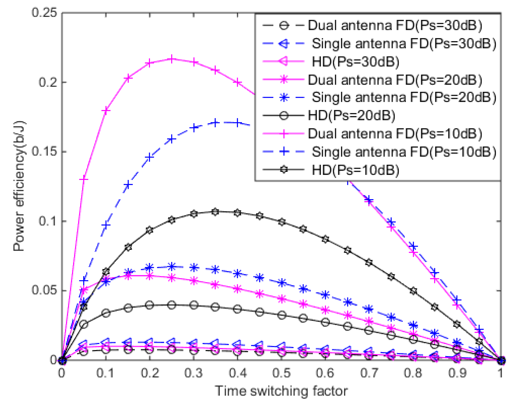
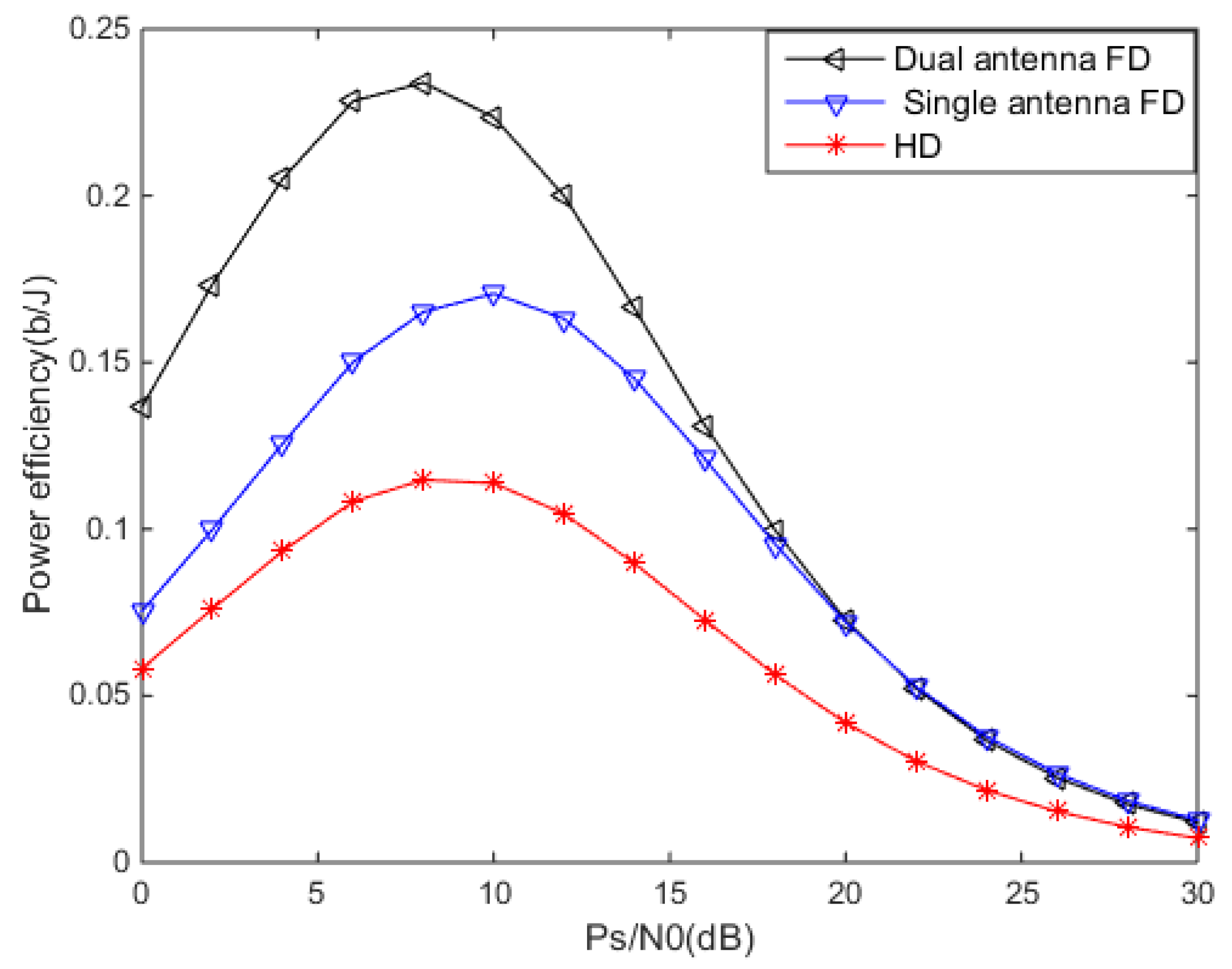
The system energy efficiency performance for different values is shown in Figure 3 under three schemes (FD dual-antenna energy harvesting, FD single-antenna energy harvesting, and HD) and fixed . According to Figure 3, under the different transmission powers, the energy efficiency trend under the three schemes is the same, specifically that it monotonically increases first, then monotonically decreases with the time-switching factor, because the energy collected in this short period of time is insufficient to satisfy the second stage of information transmission. At this time, the larger the time allocation factor, the greater the system energy efficiency. When the time-switching factor is greater than 0.6, the energy efficiency curve of the FD single antenna and the FD single-antenna energy harvesting system are almost identical, and they all gradually decrease as the time allocation factor increases. As a result, long periods of energy harvesting can degrade system performance. According to Figure 3, the optimal time allocation factor of the FD dual antenna is smaller than that of HD and the optimal time allocation factor of HD is smaller than that of the FD single antenna. This is because the extra antenna reduces the energy collection time.
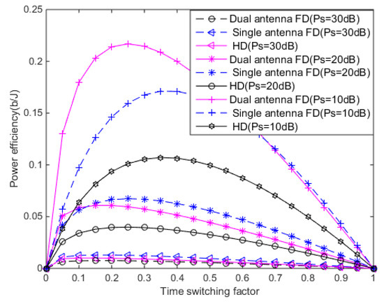
Figure 3.
The system energy efficiency versus with .
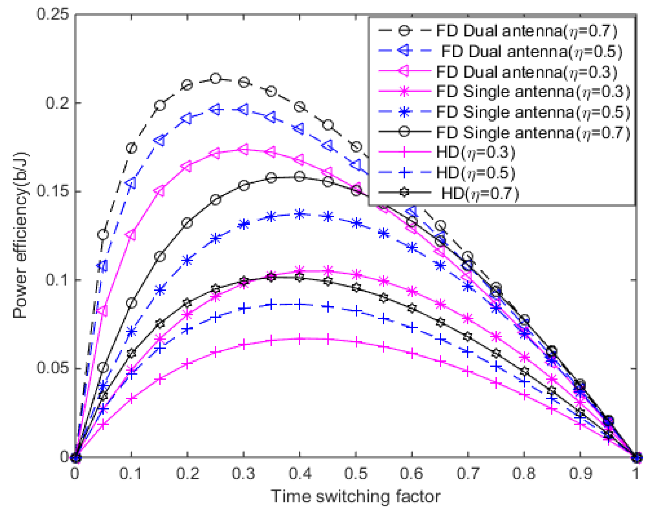
Figure 4 shows how the energy efficiency varies with time allocation factors in three cases (FD dual-antenna, FD single antenna, and HD). The energy conversion efficiencies are 0.7, 0.5, and 0.3, respectively. We set . According to Figure 4, the energy efficiency of the FD relay system is much better than the HD relay system. The energy efficiency of the FD dual-antenna energy harvesting system is better than that of the single antenna.
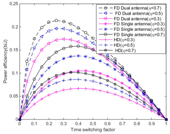
Figure 4.
The system energy efficiency versus with and .
In wireless power communication systems, the increase of not only has a positive impact on system performance, but also a certain negative impact on system performance. Figure 5 shows the variation of system energy efficiency with in three cases (FD dual-antenna, FD single-antenna, and HD) when the time factor is optimal and the energy conversion efficiency is 0.7. According to Figure 5, the system energy efficiency of HD dual antennas for energy harvesting is greater than that of HD single-antenna energy harvesting system at the same transmission power, especially at low . Because of the same transmitted power, the FD dual-antenna energy harvesting system obtains more energy per unit time for information transmission. However, with the gradual increase of the transmitting power, an antenna obtains enough energy, and excessive energy harvesting causes greater loopback interference, which reduces the performance of the system. Therefore, when the transmission power is large, the effect of the extra antenna on the system energy efficiency gradually reduces. At this time, the effects of the FD dual-antenna and FD single-antenna schemes on the system energy efficiency are not much different, and the curves almost coincide. At the same time, regardless of whether the signal-to-noise ratio is high or low, the system energy efficiency of the FD system is always greater than that of the HD system. FD significantly improves the performance of the system.
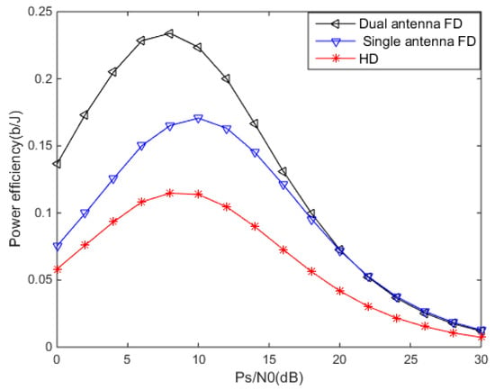
Figure 5.
The system energy efficiency versus with optimized .
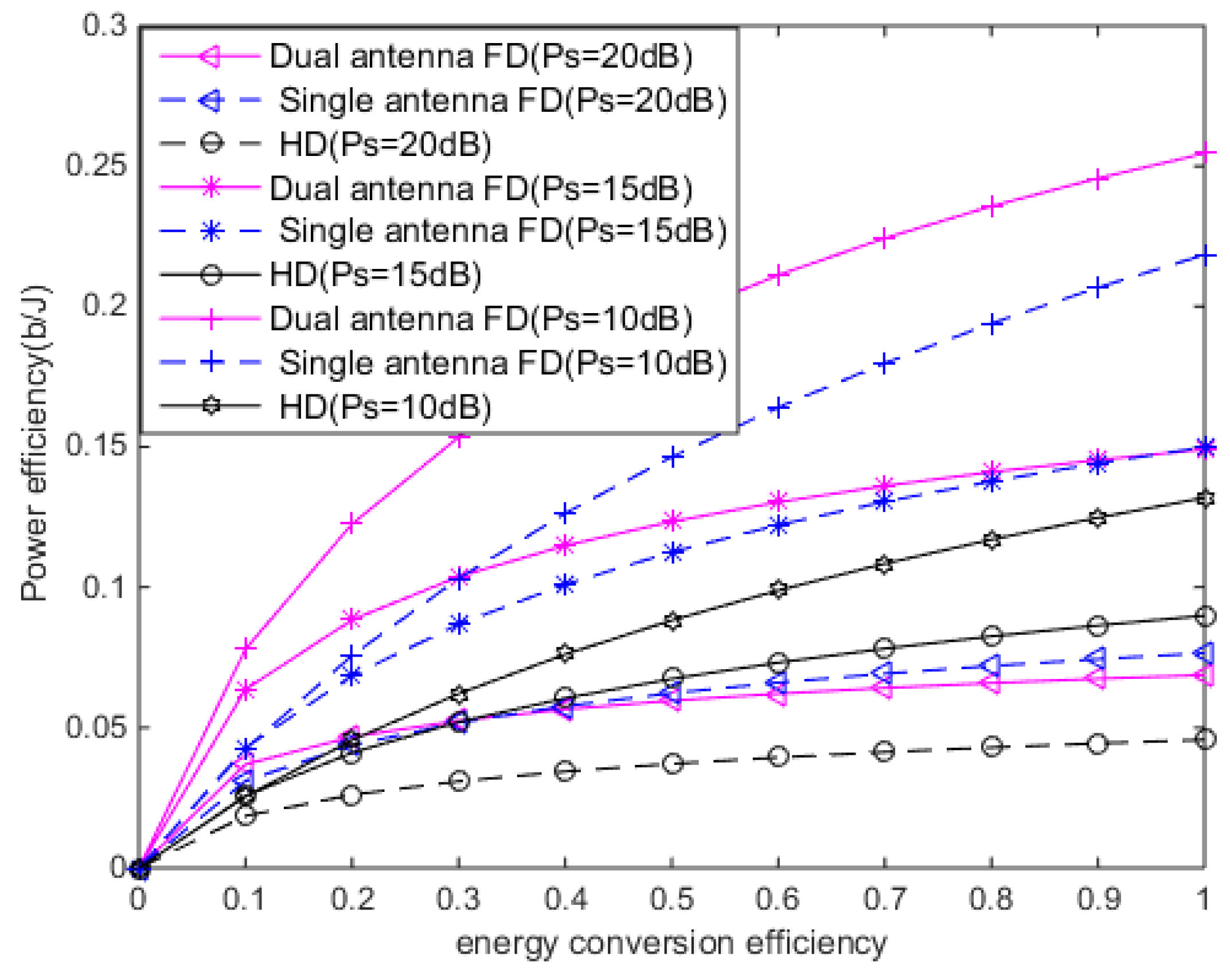
The energy conversion efficiency determines how much power the relay can actually receive. The larger the relay, the more energy the relay can receive, thereby increasing the transmitting power at the relay node to enhance the signal to interference and noise ratio at the destination node. This leads to higher system energy efficiency. Figure 6 shows the variation of the system energy efficiency with the energy conversion efficiency when the transmission power is 20 dB, 15 dB, and 10 dB, respectively. The energy efficiency increases as the energy conversion efficiency increases. From the Figure 6, we can also observe that under the three schemes, the speed of energy efficiency increase is rapid and then levels off.
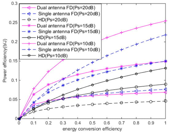
Figure 6.
The system energy efficiency versus when .
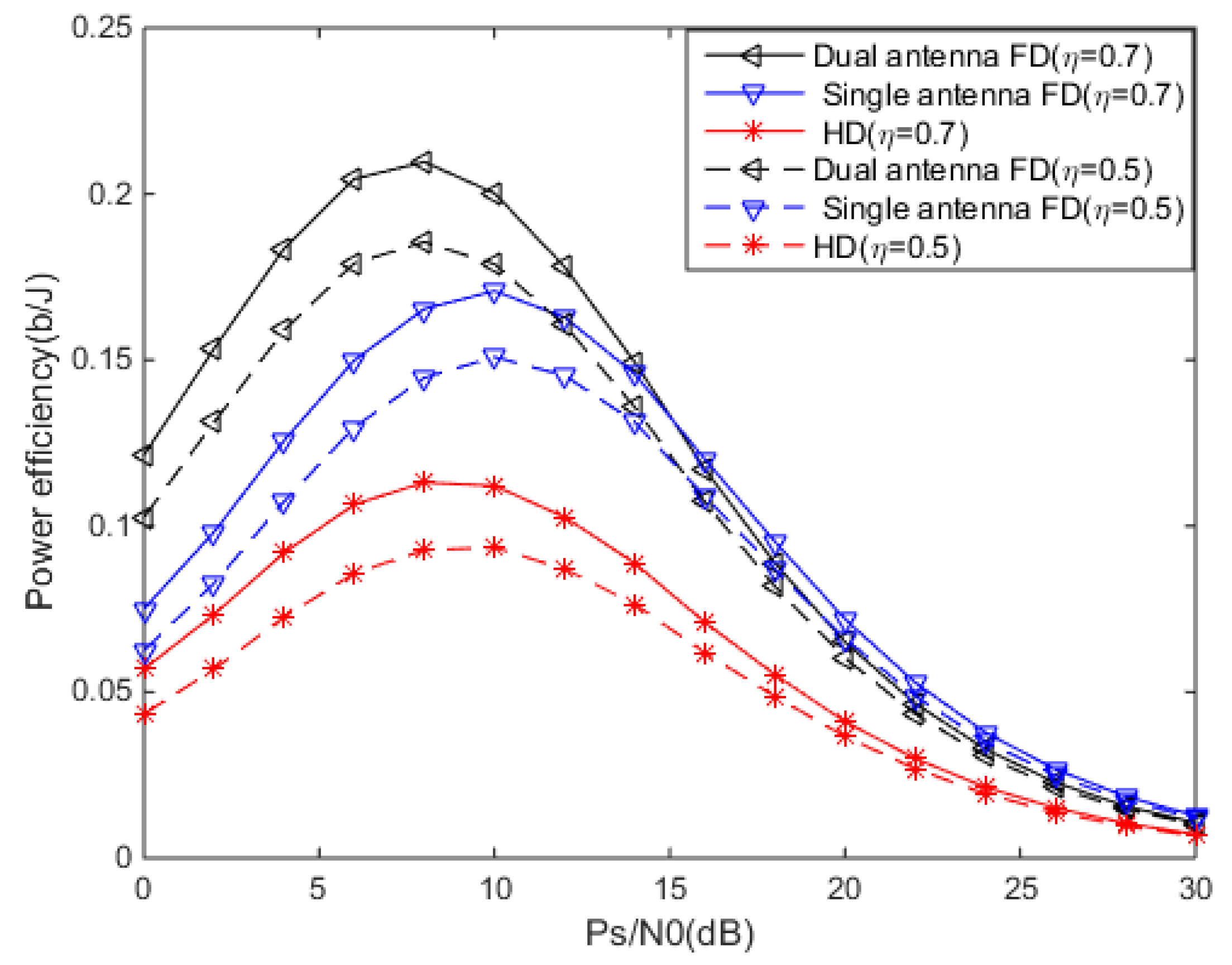
Figure 7 shows the system energy efficiency performance of FD dual-antenna energy harvesting, FD single-antenna energy harvesting, and HD when the is different. The energy conversion efficiencies are 0.7 and 0.5, respectively. At this point, we set the time conversion factor to 0.4. According to Figure 5, the system energy efficiency of the FD system is always greater than that of the HD system.
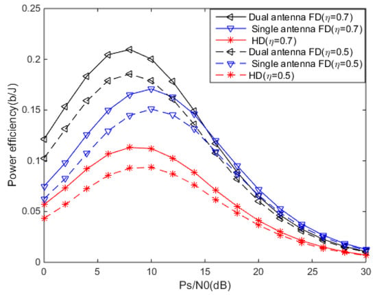
Figure 7.
The system energy efficiency versus when and .
7. Conclusions
This paper studied the energy efficiency of a full-duplex relay system for RF energy harvesting using two protocols, namely DF protocol and time-switching protocol (TS). According to the number of antennas used in the energy harvesting process, the system was analyzed from two angles. An optimal time and optimal power allocation scheme to maximize system energy efficiency was proposed. By calculating the time-switching threshold, we divided time into two parts and discussed them separately. We proved that energy efficiency was a concave function and a monotone decreasing function respective to time. By using the properties of the Lambert function, we worked out the optimal time allocation factor, then the optimal power distribution scheme was obtained by finding the derivative function of energy efficiency with respect to power. We compared the time and power allocation schemes for maximizing energy efficiency under the three schemes (FD dual-antenna energy collection, FD single antenna energy collection, and HD). The results showed that the energy efficiency of the FD dual-antenna energy harvesting was better than that of the FD single-antenna energy harvesting, and the simulation results also showed that the energy efficiency in FD mode was much better than that of the HD mode; therefore, the system performance was significantly improved.
Author Contributions
Conceptualization, Y.N.; data curation, Y.N.; formal analysis, Y.N.; funding acquisition, X.S.; methodology, Y.N.; project administration, X.S.; software, Y.N.; supervision, X.S.; validation, Y.N. and X.H.; visualization, Y.N.; writing—original draft, Y.N.; writing—review and editing, X.S., Y.N., L.D. and L.Q.
Funding
This research received no external funding.
Conflicts of Interest
The authors declare no conflict of interest.
References
- Medepally, B.; Mehta, N.B. Voluntary Energy Harvesting Relays and Selection in Cooperative Wireless Networks. IEEE Trans. Wirel. Commun. 2010, 9, 3543–3553. [Google Scholar] [CrossRef]
- Venkata, P.T.; Nambi, S.A.U.; Prasad, R.V.; Niemegeers, I. Bond Graph Modeling for Energy-Harvesting Wireless Sensor Networks. Computer 2012, 45, 31–38. [Google Scholar] [CrossRef]
- Varshney, L. Transporting information and energy simultaneously. In Proceedings of the 2008 IEEE International Symposium on Information Theory, Toronto, ON, Canada, 6–11 July 2008; pp. 1612–1616. [Google Scholar]
- Grover, P.; Sahai, A. Shannon meets Tesla: Wireless information and power transfer. In Proceedings of the 2010 IEEE International Symposium on Information Theory, Austin, TX, USA, 13–18 June 2010; Volume 19, pp. 2363–2367. [Google Scholar]
- Nasir, A.A.; Zhou, X.; Durrani, S.; Kennedy, R.A. Wireless-powered relays in cooperative communications: Time-switching relaying protocols and throughput analysis. IEEE Trans. Commun. 2015, 63, 1607–1622. [Google Scholar] [CrossRef]
- Dong, Y.; Hossain, M.J.; Cheng, J. Joint Power Control and Time Switching for SWIPT Systems with Heterogeneous QoS Requirements. IEEE Commun. Lett. 2016, 20, 328–331. [Google Scholar] [CrossRef]
- Zhai, C.; Liu, J. Cooperative wireless energy harvesting and information transfer in stochastic networks. EURASIP J. Wirel. Commun. Netw. 2015, 2015, 44. [Google Scholar] [CrossRef][Green Version]
- Liu, L.; Zhang, R.; Chua, K.C. Wireless information and power transfer in an underlay cognitive radio network. In Proceedings of the International Conference on Signal Processing and Communication Systems (ICSPCS), Gold Coast, Australia, 16–18 December 2013; Volume 12, pp. 288–300. [Google Scholar]
- Liu, L.; Zhang, R.; Chua, K.C. Wireless Information and Power Transfer: A Dynamic Power Splitting Approach. IEEE Trans. Commun. 2013, 61, 3390–4001. [Google Scholar] [CrossRef]
- Zhong, C.J.; Himal, A.S.; Zheng, G. Improving the Throughput of Wireless Powered Dual-hop Systems with Full Duplex Relaying. In Proceedings of the 2015 IEEE International Conference on Communications (ICC), London, UK, 8–12 June 2015; Volume 10, pp. 4253–4258. [Google Scholar]
- Liu, Y. Wireless Information and Power Transfer for Multirelay-Assisted Cooperative Communication. IEEE Commun. Lett. 2016, 20, 784–787. [Google Scholar] [CrossRef]
- Ju, H.; Zhang, R. Throughput Maximization in Wireless Powered Communication Networks. IEEE Trans. Wirel. Commun. 2014, 13, 418–428. [Google Scholar] [CrossRef]
- Zhang, C.; Chen, Y. Wireless Power Transfer Strategies for Cooperative Relay System to Maximize Information Throughput. IEEE Access 2017, 5, 2573–2582. [Google Scholar] [CrossRef]
- Yang, Z.; Ding, Z.; Fan, P.; Karagiannidis, G.K. Outage Performance of Cognitive Relay Networks with Wireless Information and Power Transfer. IEEE Trans. Veh. Tech. 2016, 65, 3828–3833. [Google Scholar] [CrossRef]
- Ng, D.W.K.; Lo, E.S.; Schober, R. Wireless Information and Power Transfer: Energy Efficiency Optimization in OFDMA Systems. IEEE Trans. Wirel. Commun. 2013, 12, 6352–6370. [Google Scholar] [CrossRef]
- Abrol, A.; Jha, R.K. Power Optimization in 5G Networks: A Step Towards Green Communication. IEEE Access 2016, 4, 1355–1374. [Google Scholar] [CrossRef]
- Gu, Y.; Aissa, S. RF-Based Energy Harvesting in Decode-and Forward Relay Systems: Ergodic and Outage Capacities. IEEE Trans. Wirel. Commun. 2015, 14, 6425–6434. [Google Scholar] [CrossRef]
- Riihonen, T.; Werner, S.; Wichman, R. Mitigation of Loopback Self-Interference in Full-Duplex MIMO Relays. IEEE Trans. Signal Process. 2011, 59, 5983–5993. [Google Scholar] [CrossRef]
- Riihonen, T.; Werner, S.; Wichman, R. Hybrid Full-Duplex/Half-Duplex Relaying with Transmit Power Adaptation. IEEE Trans. Wirel. Commun. 2011, 10, 3074–3085. [Google Scholar] [CrossRef]
- Day, B.P.; Margetts, A.R.; Bliss, W.D.; Schniter, P. Full-Duplex MIMO Relaying: Achievable Rates Under Limited Dynamic Range. IEEE J. Sel. Areas Commun. 2012, 30, 1541–1553. [Google Scholar] [CrossRef]
- Sabharwal, A.; Schniter, P.; Guo, D.; Bliss, D.; Rangarajan, S.; Wichman, R. In-Band Full-Duplex Wireless: Challenges and Opportunities. IEEE J. Sel. Areas Commun. 2014, 32, 1637–1652. [Google Scholar] [CrossRef]
- Krikidis, I.; Suraweera, H.A.; Smith, P.J.; Yuen, C. Full-Duplex Relay Selection for Amplify-and-Forward Cooperative Networks. IEEE Trans. Wirel. Commun. 2012, 11, 4381–4393. [Google Scholar] [CrossRef]
- Mohammadi, M.; Chalise, B.K.; Suraweera, H.A.; Zhong, C.; Zheng, G.; Krikidis, I. Throughput Analysis and Optimization of Wireless-Powered Multiple Antenna Full-Duplex Relay Systems. IEEE Trans. Commun. 2016, 64, 1769–1785. [Google Scholar] [CrossRef]
- Zhang, C.; Suraweera, H.A.; Zheng, G.; Krikidis; Zhang, Z. Wireless Information and Power Transfer With Full-Duplex Relaying. IEEE Trans. Commun. 2014, 62, 3447–3461. [Google Scholar] [CrossRef]
- Lee, C.-H.; Chang, R.Y.; Lin, C.-T.; Cheng, S.-M. Sum-rate maximization for energy harvesting-aided D2D communications underlaid cellular networks. In Proceedings of the 2017 IEEE 28th Annual International Symposium on Personal, Indoor, and Mobile Radio Communications (PIMRC), Montreal, QC, Canada, 8–13 October 2017. [Google Scholar]
- Zhao, L.; Wang, X.; Riihonen, T. Transmission Rate Optimization of Full-Duplex Relay Systems Powered by Wireless Energy Transfer. IEEE Trans. Wirel. Commun. 2017, 16, 6348–6450. [Google Scholar] [CrossRef]
- Zhou, X.; Zhang, R.; Ho, C.K. Wireless information and power transfer: Architecture design and rate-energy tradeoff. IEEE Commun. Lett. 2013, 61, 4754–4767. [Google Scholar] [CrossRef]
- Mou, W.; Cai, Y.; Yang, W.; Yang, W.; Xu, X.; Hu, J. Exploiting full Duplex techniques for secure communication in SWIPT system. In Proceedings of the International Conference on Wireless Communications & Signal Processing (WCSP), Nanjing, China, 15–17 October 2015; pp. 1–6. [Google Scholar]
- Chen, H.; Li, Y.; Rebelatto, J.L.; Uchoa-Filho, B.F.; Vucetic, B. Harvest-Then-Cooperate: Wireless-Powered Cooperative Communications. IEEE Trans. Signal Process. 2015, 63, 1700–1711. [Google Scholar] [CrossRef]
- Nasir, A.A.; Zhou, X.; Durrani, S.; Kennedy, R.A. Relaying protocols for wireless energy harvesting and information processing. IEEE Commun. Lett. 2013, 12, 3622–3636. [Google Scholar] [CrossRef]
- Bharadia, D.; McMilin, E.; Katti, S. Full duplex radios. In Proceedings of the 2013 ACM SIGCOMM, Hong Kong, China, 12–16 August 2013; pp. 375–386. [Google Scholar]
- Chen, G.; Gong, Y.; Xiao, P.; Chambers, J.A. Physical layer network security in the full-duplex relay system. IEEE Access 2015, 10, 574–583. [Google Scholar] [CrossRef]
© 2019 by the authors. Licensee MDPI, Basel, Switzerland. This article is an open access article distributed under the terms and conditions of the Creative Commons Attribution (CC BY) license (http://creativecommons.org/licenses/by/4.0/).

