
Integrated Purification and Formulation of an Active Pharmaceutical Ingredient via Agitated Bed Crystallization and Fluidized Bed Processing

 ,
,  and
and
Abstract
:
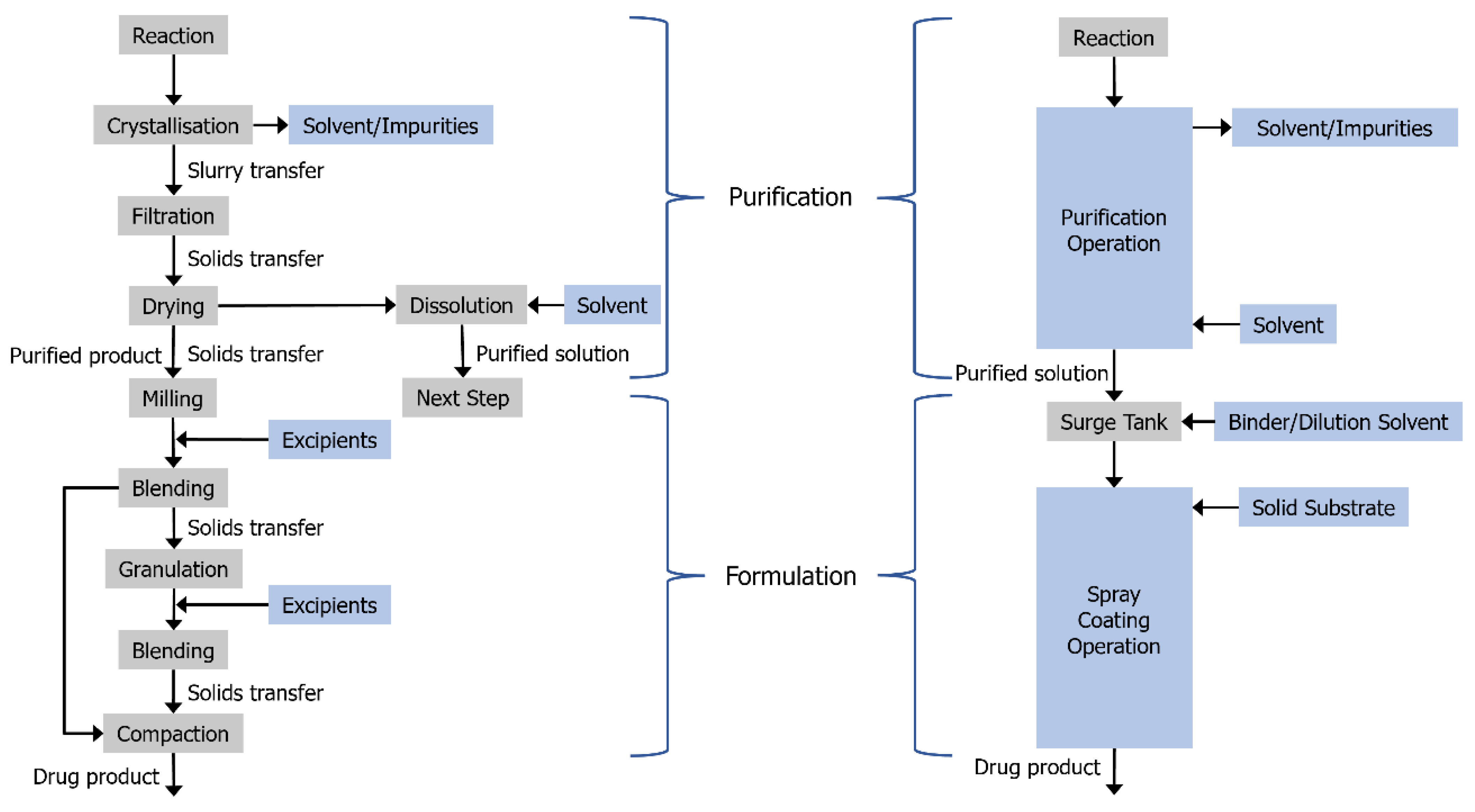
1. Introduction
2. Materials and Methods
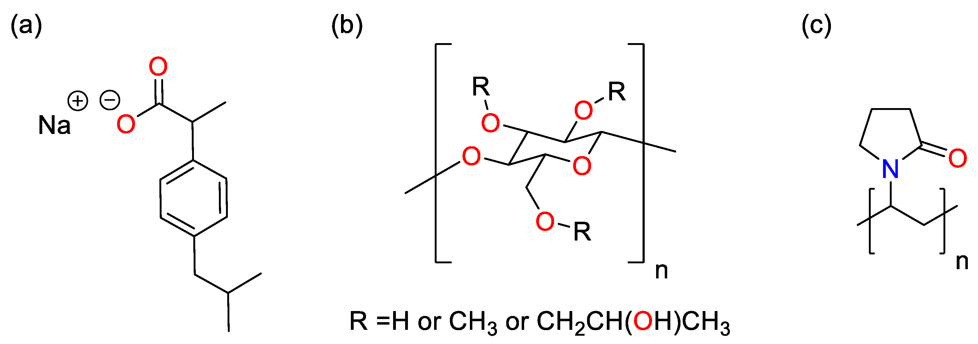
2.1. Materials
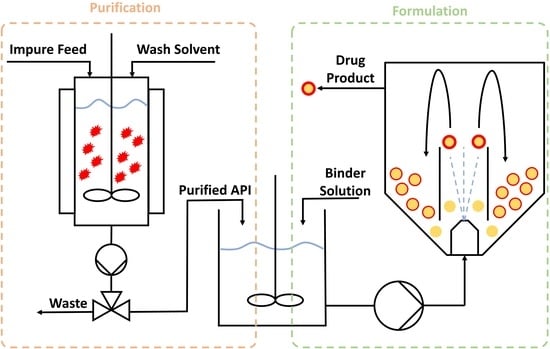
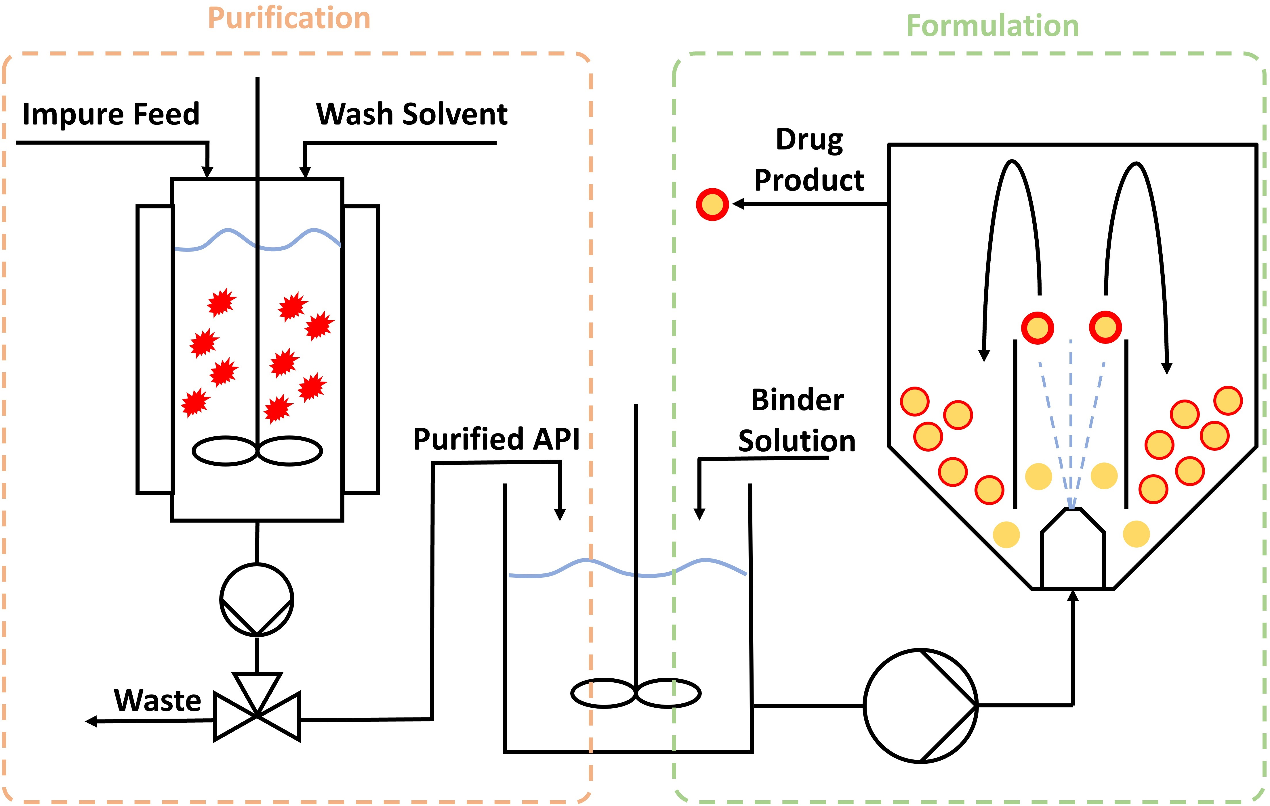
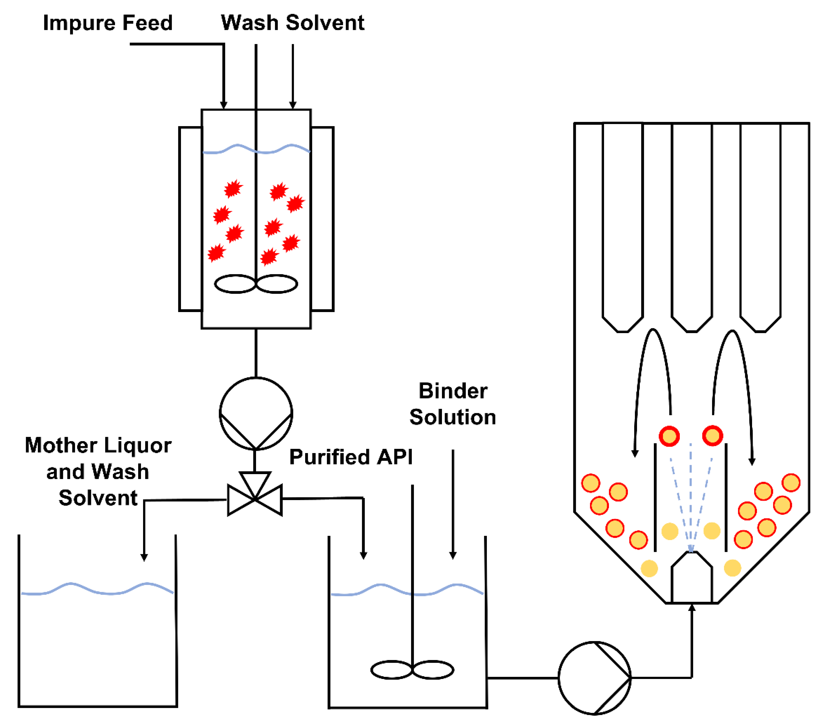
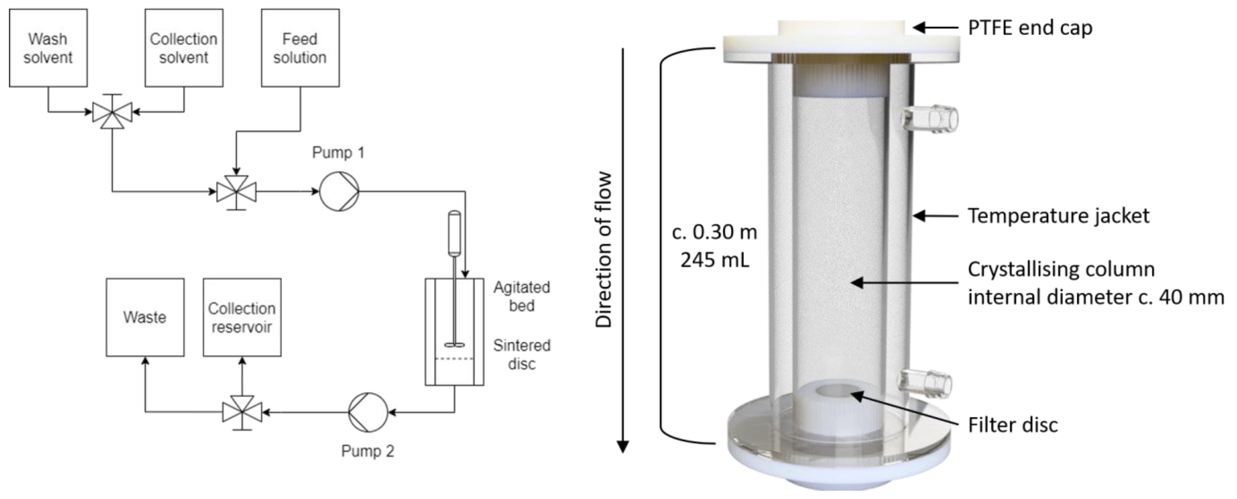
2.2. Agitated Bed Crystallizer
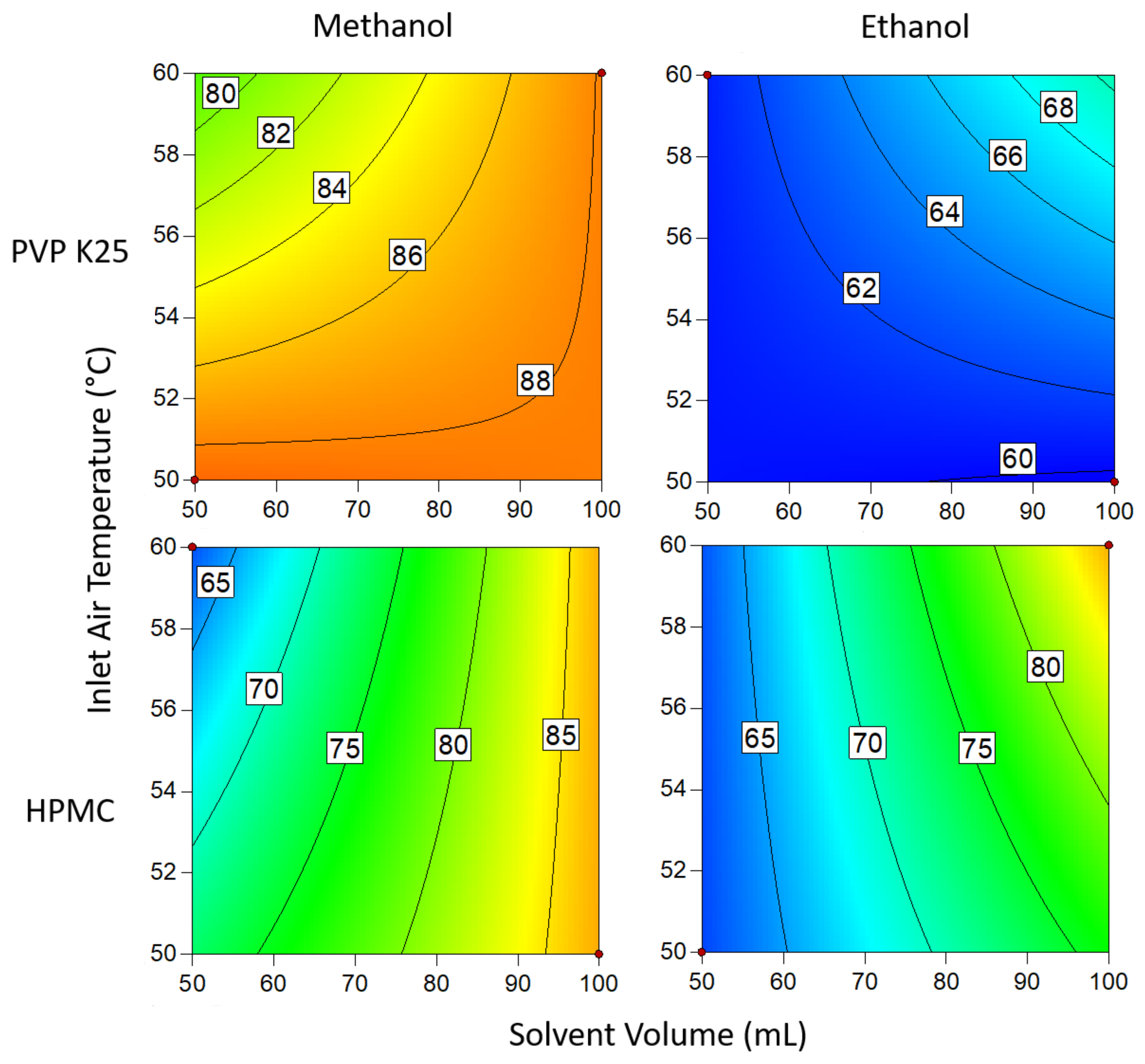
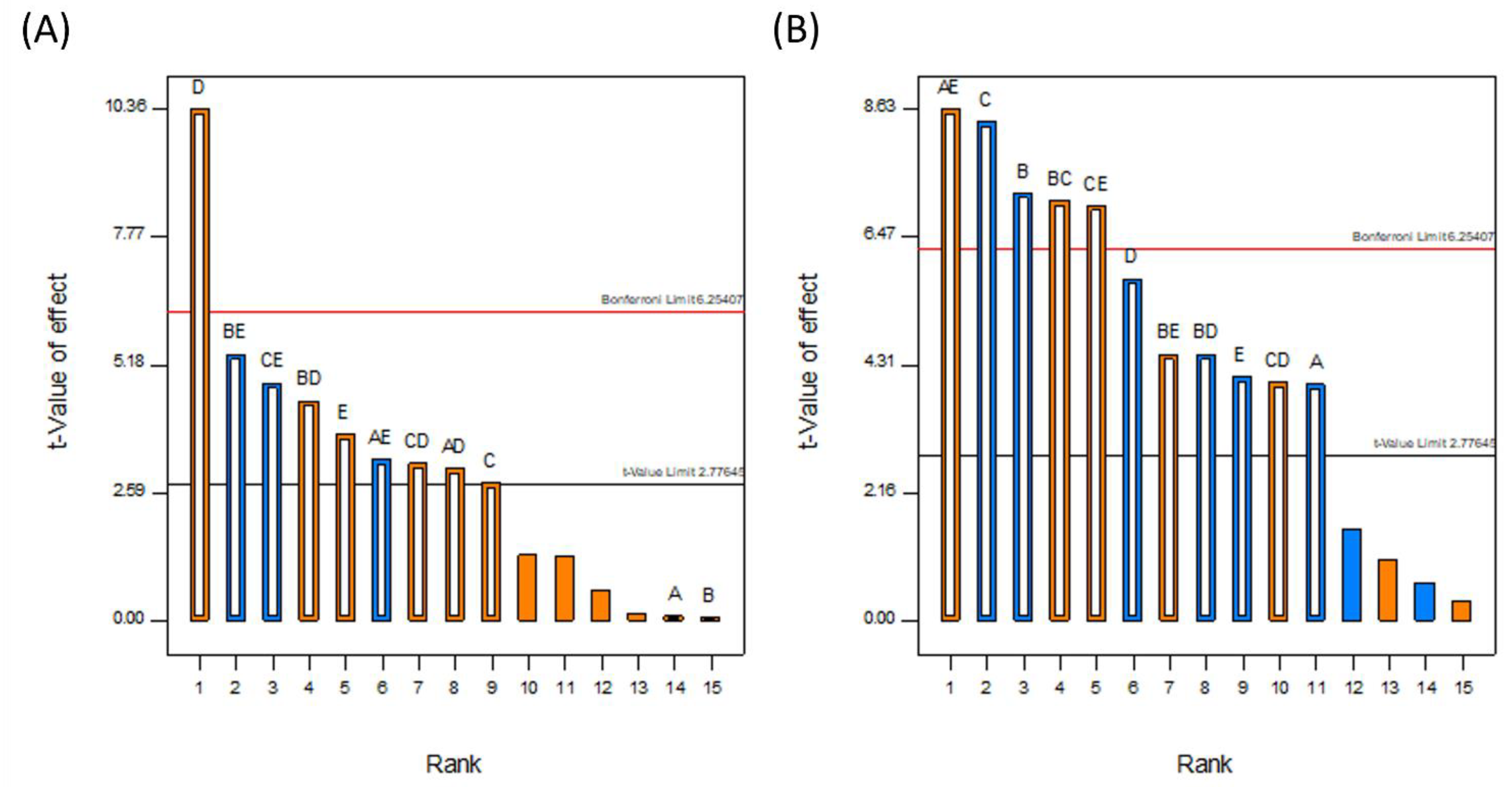
2.3. Design of Experiments (DoE)
- Solution feed rate: 2.1 mL min−1
- Fluidizing air flow: 30 m3 h−1
- Atomization pressure: 2 bar
- A. Inlet air temperature: 50 or 60 °C
- B. Binder type: PVP or HPMC
- C. Binder mass: 1 or 3 g
- D. Solvent volume: 50 or 100 mL
- E. Solvent: methanol or ethanol
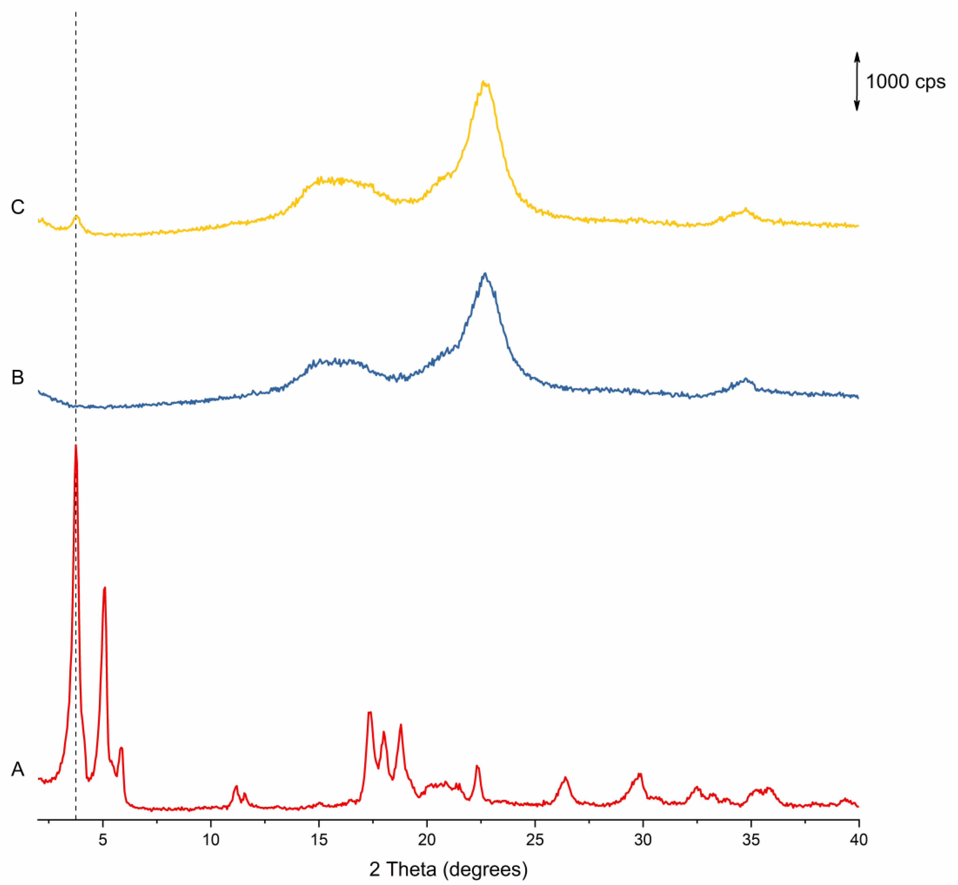
2.4. Powder X-ray Diffraction (pXRD)
2.5. Drug Loading Efficiency (DLE)
2.6. Degree of Crystallinity (DoC)
3. Results and Discussion
3.1. Fluidised Bed Coating Process Development
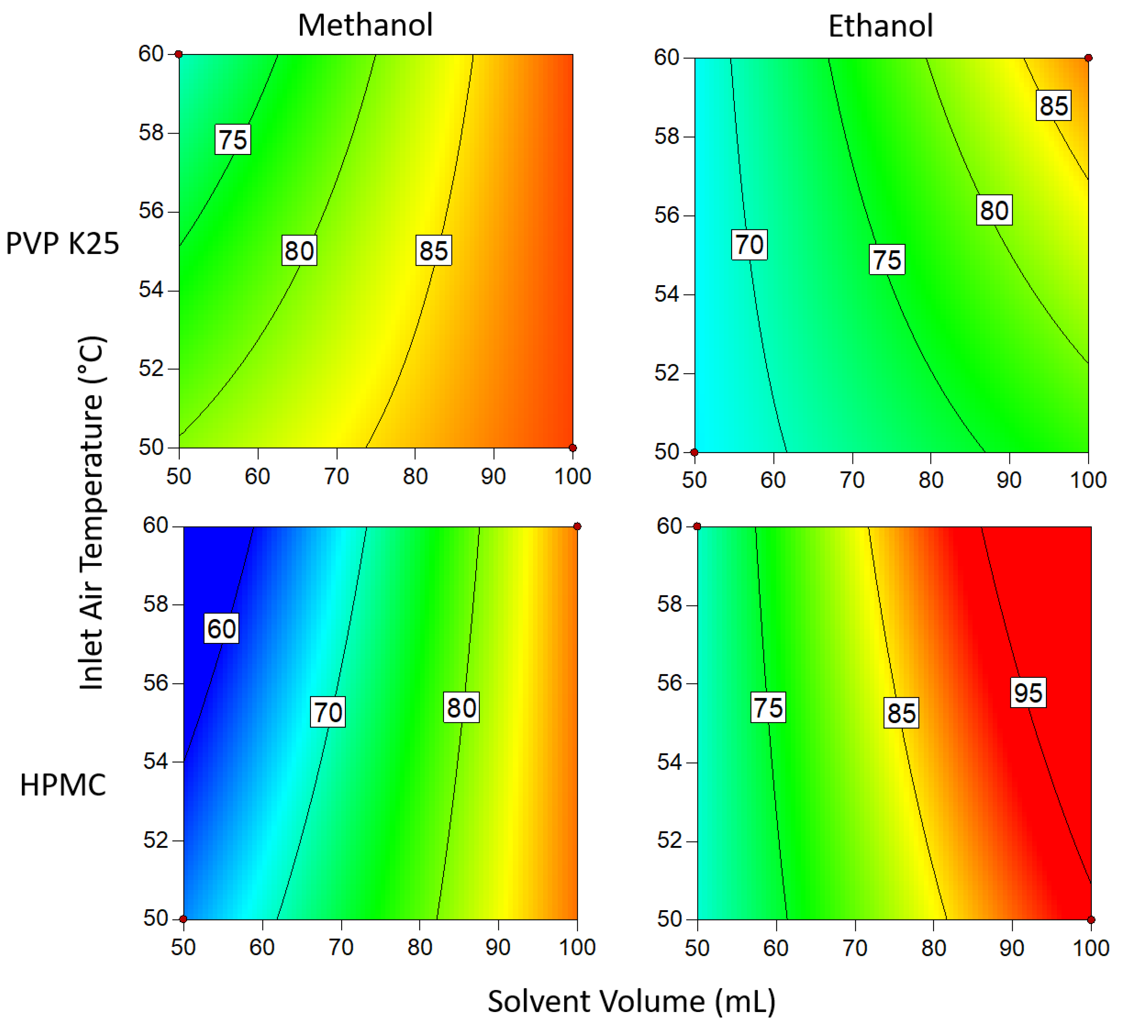
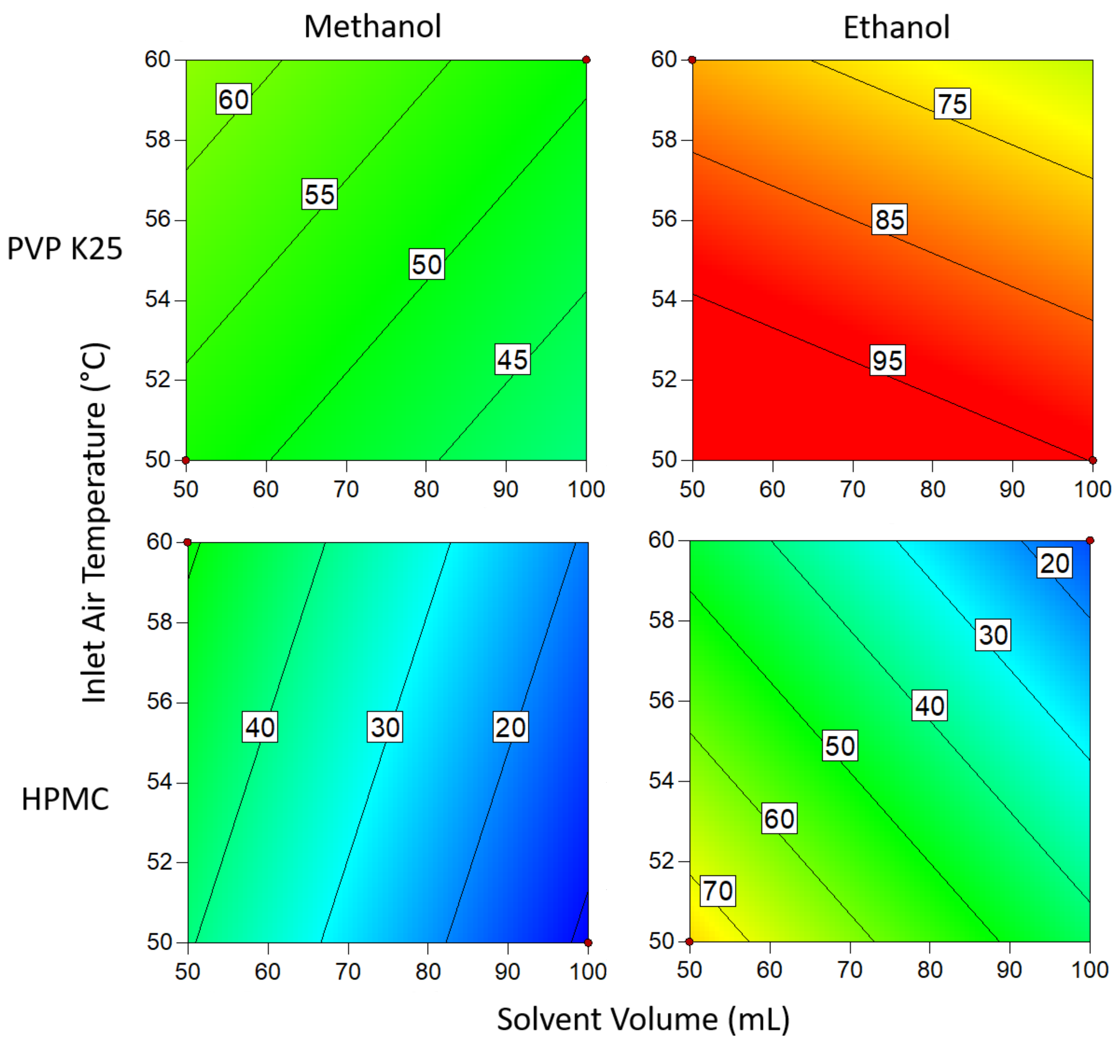
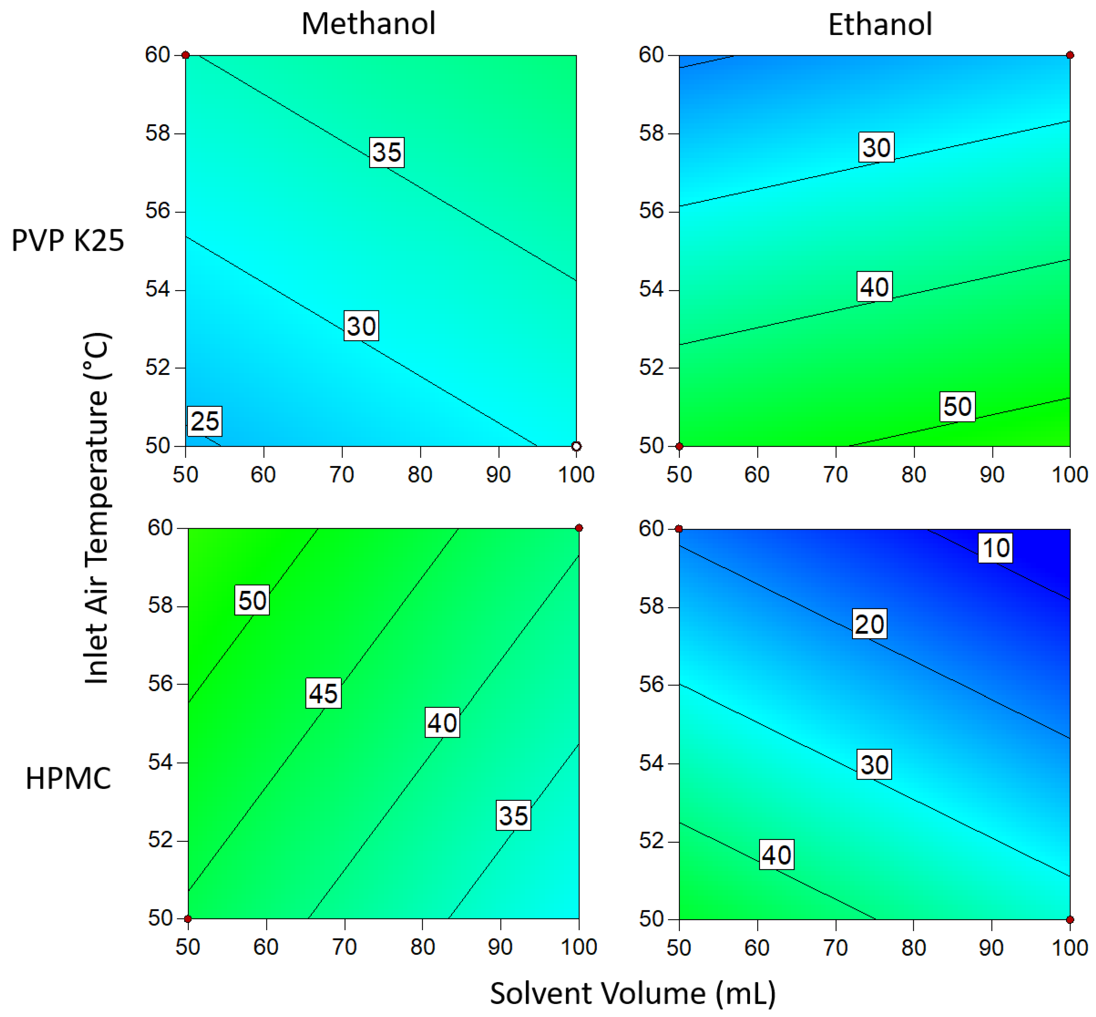
3.1.1. DoE Characterization Study
3.1.2. pXRD
3.1.3. Drug Loading Efficiency
3.1.4. Degree of Crystallinity
3.2. Combining Crystallisation and Spray Coating Operations
4. Conclusions
Supplementary Materials
Author Contributions
Funding
Data Availability Statement
Conflicts of Interest
References
- Tung, H.H. Industrial Perspectives of Pharmaceutical Crystallization. Org. Process Res. Dev. 2013, 17, 445–454. [Google Scholar] [CrossRef]
- Variankaval, N.; Cote, A.S.; Doherty, M.F. From Form to Function: Crystallization of Active Pharmaceutical Ingredients. AIChE J. 2008, 54, 1682–1688. [Google Scholar] [CrossRef]
- Wood, B.; Girard, K.P.; Polster, C.S.; Croker, D.M. Progress to Date in the Design and Operation of Continuous Crystallization Processes for Pharmaceutical Applications. Org. Process Res. Dev. 2019, 23, 122–144. [Google Scholar] [CrossRef]
- Quon, J.L.; Zhang, H.; Alvarez, A.; Evans, J.; Myerson, A.S.; Trout, B.L. Continuous Crystallization of Aliskiren Hemifumarate. Cryst. Growth Des. 2012, 12, 3036–3044. [Google Scholar] [CrossRef]
- Li, J.; Trout, B.L.; Myerson, A.S. Multistage Continuous Mixed-Suspension, Mixed-Product Removal (MSMPR) Crystallization with Solids Recycle. Org. Process Res. Dev. 2016, 20, 510–516. [Google Scholar] [CrossRef]
- Wang, T.; Lu, H.; Wang, J.; Xiao, Y.; Zhou, Y.; Bao, Y.; Hao, H. Recent Progress of Continuous Crystallization. J. Ind. Eng. Chem. 2017, 54, 14–29. [Google Scholar] [CrossRef]
- Gao, Z.; Wu, Y.; Gong, J.; Wang, J.; Rohani, S. Continuous crystallization of α-form L-glutamic acid in an MSMPR-Tubular crystallizer system. J. Cryst. Growth 2019, 507, 344–351. [Google Scholar] [CrossRef]
- Köllges, T.; Vetter, T. Polymorph Selection and Process Intensification in a Continuous Crystallization-Milling Process: A Case Study on l -Glutamic Acid Crystallized from Water. Org. Process Res. Dev. 2019, 23, 361–374. [Google Scholar] [CrossRef]
- Hu, C.; Testa, C.J.; Shores, B.T.; Wu, W.; Shvedova, K.; Born, S.C.; Chattopadhyay, S.; Takizawa, B.; Mascia, S. An experimental study on polymorph control and continuous heterogeneous crystallization of carbamazepine. CrystEngComm 2019, 21, 5076–5083. [Google Scholar] [CrossRef]
- Acevedo, D.; Jarmer, D.J.; Burcham, C.L.; Polster, C.S.; Nagy, Z.K. A Continuous Multi-Stage Mixed-Suspension Mixed-Product-Removal Crystallization System with Fines Dissolution. Chem. Eng. Res. Des. 2018, 135, 112–120. [Google Scholar] [CrossRef]
- Farmer, T.C.; Carpenter, C.L.; Doherty, M.F. Polymorph Selection by Continuous Crystallization. AIChE J. 2016, 62, 3505–3514. [Google Scholar] [CrossRef]
- Farmer, T.C.; Schiebel, S.K.; Chmelka, B.F.; Doherty, M.F. Polymorph Selection by Continuous Precipitation. Cryst. Growth Des. 2018, 18, 4306–4319. [Google Scholar] [CrossRef]
- Lai, T.T.C.; Cornevin, J.; Ferguson, S.; Li, N.; Trout, B.L.; Myerson, A.S. Control of Polymorphism in Continuous Crystallization via Mixed Suspension Mixed Product Removal Systems Cascade Design. Cryst. Growth Des. 2015, 15, 3374–3382. [Google Scholar] [CrossRef]
- Lai, T.T.C.; Ferguson, S.; Palmer, L.; Trout, B.L.; Myerson, A.S. Continuous Crystallization and Polymorph Dynamics in the l -Glutamic Acid System. Org. Process Res. Dev. 2014, 18, 1382–1390. [Google Scholar] [CrossRef]
- Chen, J.; Sarma, B.; Evans, J.M.B.; Myerson, A.S. Pharmaceutical Crystallization. Cryst. Growth Des. 2011, 11, 887–895. [Google Scholar] [CrossRef] [Green Version]
- Ferguson, S.; Ortner, F.; Quon, J.; Peeva, L.; Livingston, A.; Trout, B.L.; Myerson, A.S. Use of Continuous MSMPR Crystallization with Integrated Nanofiltration Membrane Recycle for Enhanced Yield and Purity in API Crystallization. Cryst. Growth Des. 2014, 14, 617–627. [Google Scholar] [CrossRef]
- Zhang, H.; Lakerveld, R.; Heider, P.L.; Tao, M.; Su, M.; Testa, C.J.; D’Antonio, A.N.; Barton, P.I.; Braatz, R.D.; Trout, B.L.; et al. Application of Continuous Crystallization in an Integrated Continuous Pharmaceutical Pilot Plant. Cryst. Growth Des. 2014, 14, 2148–2157. [Google Scholar] [CrossRef]
- Power, G.; Hou, G.; Kamaraju, V.K.; Morris, G.; Zhao, Y.; Glennon, B. Design and Optimization of a Multistage Continuous Cooling Mixed Suspension, Mixed Product Removal Crystallizer. Chem. Eng. Sci. 2015, 133, 125–139. [Google Scholar] [CrossRef]
- Webb, D.; Jamison, T.F. Continuous Flow Multi-Step Organic Synthesis. Chem. Sci. 2010, 1, 675–680. [Google Scholar] [CrossRef] [Green Version]
- Chen, Y.; Sabio, J.C.; Hartman, R.L. When Solids Stop Flow Chemistry in Commercial Tubing. J. Flow Chem. 2015, 5, 166–171. [Google Scholar] [CrossRef] [Green Version]
- Yazdanpanah, N.; Ferguson, S.T.; Myerson, A.S.; Trout, B.L. Novel Technique for Filtration Avoidance in Continuous Crystallization. Cryst. Growth Des. 2016, 16, 285–296. [Google Scholar] [CrossRef]
- Lopez-Rodriguez, R.; Harding, M.J.; Gibson, G.; Girard, K.P.; Ferguson, S. Design of a Combined Modular and 3D-Printed Falling Film Solution Layer Crystallizer for Intermediate Purification in Continuous Production of Pharmaceuticals. Ind. Eng. Chem. Res. 2021, 60, 10276–10285. [Google Scholar] [CrossRef] [PubMed]
- Myerson, A.S.; Erdemir, D.; Lee, A.Y. Handbook of Industrial Crystallization, 3rd ed.; Myerson, A.S., Erdemir, D., Lee, A.Y., Eds.; Cambridge University Press: Cambridge, UK, 2019; ISBN 9781139026949. [Google Scholar]
- Douroumis, D. Orally Disintegrating Dosage Forms and Taste-Masking Technologies; 2010. Expert Opin. Drug Deliv. 2011, 8, 665–675. [Google Scholar] [CrossRef] [PubMed]
- Joshi, S.; Petereit, H.-U. Film Coatings for Taste Masking and Moisture Protection. Int. J. Pharm. 2013, 457, 395–406. [Google Scholar] [CrossRef] [PubMed]
- Kazlauske, J.; Cafaro, M.M.; Caccavo, D.; Marucci, M.; Lamberti, G.; Barba, A.A.; Larsson, A. Determination of the Release Mechanism of Theophylline from Pellets Coated with Surelease ® —A Water Dispersion of Ethyl Cellulose. Int. J. Pharm. 2017, 528, 345–353. [Google Scholar] [CrossRef]
- Ehlers, H.; Räikkönen, H.; Antikainen, O.; Heinämäki, J.; Yliruusi, J. Improving Flow Properties of Ibuprofen by Fluidized Bed Particle Thin-Coating. Int. J. Pharm. 2009, 368, 165–170. [Google Scholar] [CrossRef]
- Rhodes, C.T.; Porter, S.C. Coatings for Controlled-Release Drug Delivery Systems. Drug Dev. Ind. Pharm. 1998, 24, 1139–1154. [Google Scholar] [CrossRef]
- Christensen, F.N.; Bertelsen, P. Qualitative Description of the Wurster-Based Fluid-Bed Coating Process. Drug Dev. Ind. Pharm. 1997, 23, 451–463. [Google Scholar] [CrossRef]
- Cheng, X.X.; Turton, R. The Prediction of Variability Occurring in Fluidized Bed Coating Equipment in the Measurement of Particle Circulation Rates in a Bottom-Spray Fluidized Bed Coater. Pharm. Dev. Technol. 2000, 5, 311–322. [Google Scholar] [CrossRef]
- Kroselj, V. Pharmaceutical Oral Dosage Forms Comprising Dabigatran Etexilate and Its Pharmaceutically Acceptable Salts. Patent EP2588090B1, 11 July 2013. [Google Scholar]
- Kolašinac, N.; Kachrimanis, K.; Djuriš, J.; Homšek, I.; Grujić, B.; Ibrić, S. Spray Coating as a Powerful Technique in Preparation of Solid Dispersions with Enhanced Desloratadine Dissolution Rate. Drug Dev. Ind. Pharm. 2013, 39, 1020–1027. [Google Scholar] [CrossRef]
- Serrano, D.R.; Walsh, D.; O’Connell, P.; Mugheirbi, N.A.; Worku, Z.A.; Bolas-Fernandez, F.; Galiana, C.; Dea-Ayuela, M.A.; Healy, A.M. Optimising the in Vitro and in Vivo Performance of Oral Cocrystal Formulations via Spray Coating. Eur. J. Pharm. Biopharm. 2018, 124, 13–27. [Google Scholar] [CrossRef] [PubMed]
- Hinsby, A.M.; Jensen, T.K.; Bolwig, G.M.; Camozzi, C.R. Arimoclomol Formulation. U.S. Patent US20170239232A1, 24 August 2017. [Google Scholar]
- Kállai, N.; Luhn, O.; Dredán, J.; Kovács, K.; Lengyel, M.; Antal, I. Evaluation of Drug Release From Coated Pellets Based on Isomalt, Sugar, and Microcrystalline Cellulose Inert Cores. AAPS Pharm. Sci. Tech. 2010, 11, 383–391. [Google Scholar] [CrossRef] [PubMed] [Green Version]
- Arribas Bueno, R.; Crowley, C.M.; Davern, P.; Hodnett, B.K.; Hudson, S. Heterogeneous Crystallization of Fenofibrate onto Pharmaceutical Excipients. Cryst. Growth Des. 2018, 18, 2151–2164. [Google Scholar] [CrossRef]
- Verma, V.; Zeglinski, J.; Hudson, S.; Davern, P.; Hodnett, B.K. Dependence of Heterogeneous Nucleation on Hydrogen Bonding Lifetime and Complementarity. Cryst. Growth Des. 2018, 18, 7158–7172. [Google Scholar] [CrossRef] [Green Version]
- Yazdanpanah, N.; Testa, C.J.; Perala, S.R.K.; Jensen, K.D.; Braatz, R.D.; Myerson, A.S.; Trout, B.L. Continuous Heterogeneous Crystallization on Excipient Surfaces. Cryst. Growth Des. 2017, 17, 3321–3330. [Google Scholar] [CrossRef]
- Leon, R.A.L.; Wan, W.Y.; Badruddoza, A.Z.M.; Hatton, T.A.; Khan, S.A. Simultaneous Spherical Crystallization and Co-Formulation of Drug(s) and Excipient from Microfluidic Double Emulsions. Cryst. Growth Des. 2014, 14, 140–146. [Google Scholar] [CrossRef]
- Yeap, E.W.Q.; Ng, D.Z.L.; Lai, D.; Ertl, D.J.; Sharpe, S.; Khan, S.A. Continuous Flow Droplet-Based Crystallization Platform for Producing Spherical Drug Microparticles. Org. Process Res. Dev. 2019, 23, 93–101. [Google Scholar] [CrossRef]
- Hampel, N.; Bück, A.; Peglow, M.; Tsotsas, E. Continuous Pellet Coating in a Wurster Fluidized Bed Process. Chem. Eng. Sci. 2013, 86, 87–98. [Google Scholar] [CrossRef]
- Dewettinck, K.; Huyghebaert, A. Fluidized Bed Coating in Food Technology. Trends Food Sci. Technol. 1999, 10, 163–168. [Google Scholar] [CrossRef]
- Lee, T.; Zhang, C.W.; Chen, Y.H. Solubility, Polymorphism, Crystallinity, Crystal Habit, and Drying Scheme of (R, S)-(±)-Sodium Ibuprofen Dihydrate. Pharm. Technol. 2007, 31, 72–87. [Google Scholar]
- Dudognon, E.; Danède, F.; Descamps, M.; Correia, N.T. Evidence for a New Crystalline Phase of Racemic Ibuprofen. Pharm. Res. 2008, 25, 2853–2858. [Google Scholar] [CrossRef] [PubMed]
- Censi, R.; Martena, V.; Hoti, E.; Malaj, L.; di Martino, P. Sodium Ibuprofen Dihydrate and Anhydrous: Study of the Dehydration and Hydration Mechanisms. J. Therm. Anal. Calorim. 2013, 111, 2009–2018. [Google Scholar] [CrossRef]
- Todaro, V.; Healy, A.M. Development and Characterization of Ibuprofen Co-Crystals Granules Prepared via Fluidized Bed Granulation in a One-Step Process–a Design of Experiment Approach. Drug Dev. Ind. Pharm. 2021, 47, 292–301. [Google Scholar] [CrossRef] [PubMed]
- Antoy, J. Design of Experiments for Engineers and Scientists, 2nd ed.; Elsevier: Amsterdam, The Netherlands, 2014; ISBN 9780080994178. [Google Scholar]
- Jones, D. Air Suspension Coating for Multiparticulates. Drug Dev. Ind. Pharm. 1994, 20, 3175–3206. [Google Scholar] [CrossRef]
- Pearnchob, N.; Bodmeier, R. Coating of Pellets with Micronized Ethylcellulose Particles by a Dry Powder Coating Technique. Int. J. Pharm. 2003, 268, 1–11. [Google Scholar] [CrossRef]
- Tzika, M.; Alexandridou, S.; Kiparissides, C. Evaluation of the Morphological and Release Characteristics of Coated Fertilizer Granules Produced in a Wurster Fluidized Bed. Powder Technol. 2003, 132, 16–24. [Google Scholar] [CrossRef]
- Zhang, G.G.Z.; Paspal, S.Y.L.; Suryanarayanan, R.; Grant, D.J.W. Racemic Species of Sodium Ibuprofen: Characterization and Polymorphic Relationships. J. Pharm. Sci. 2003, 92, 1356–1366. [Google Scholar] [CrossRef]
- Chen, Y.; Yang, J.; Mujumdar, A.; Dave, R. Fluidized Bed Film Coating of Cohesive Geldart Group C Powders. Powder Technol. 2009, 189, 466–480. [Google Scholar] [CrossRef]
- Hemati, M.; Cherif, R.; Saleh, K.; Pont, V. Fluidized Bed Coating and Granulation: Influence of Process-Related Variables and Physicochemical Properties on the Growth Kinetics. Powder Technol. 2003, 130, 18–34. [Google Scholar] [CrossRef]
- Ronsse, F.; Pieters, J.G.; Dewettinck, K. Modelling Side-Effect Spray Drying in Top-Spray Fluidised Bed Coating Processes. J. Food Eng. 2008, 86, 529–541. [Google Scholar] [CrossRef]
- Acree, W.E. IUPAC-NIST Solubility Data Series. 102. Solubility of Nonsteroidal Anti-Inflammatory Drugs (NSAIDs) in Neat Organic Solvents and Organic Solvent Mixtures. J. Phys. Chem. Ref. Data 2014, 43, 023102. [Google Scholar] [CrossRef] [Green Version]
- Ye, F.; Jensen, H.; Larsen, S.W.; Yaghmur, A.; Larsen, C.; Østergaard, J. Measurement of Drug Diffusivities in Pharmaceutical Solvents Using Taylor Dispersion Analysis. J. Pharm. Biomed. Anal. 2012, 61, 176–183. [Google Scholar] [CrossRef] [PubMed]
- Raghavan, S.L.; Trividic, A.; Davis, A.F.; Hadgraft, J. Crystallization of Hydrocortisone Acetate: Influence of Polymers. Int. J. Pharm. 2001, 212, 213–221. [Google Scholar] [CrossRef]


| Run | Inlet Air Temperature (°C) | Binder Type | Binder Mass (g) | Solvent Volume (mL) | Solvent |
|---|---|---|---|---|---|
| 1 | 60 | HPMC | 3 | 50 | Ethanol |
| 2 | 50 | HPMC | 3 | 100 | Ethanol |
| 3 | 60 | HPMC | 1 | 100 | Ethanol |
| 4 | 60 | PVP | 3 | 100 | Ethanol |
| 5 | 60 | HPMC | 3 | 100 | Methanol |
| 6 | 60 | PVP | 1 | 50 | Ethanol |
| 7 | 50 | PVP | 1 | 50 | Methanol |
| 8 | 50 | HPMC | 1 | 100 | Methanol |
| 9 | 50 | PVP | 1 | 100 | Ethanol |
| 10 | 50 | PVP | 3 | 100 | Methanol |
| 11 | 50 | HPMC | 1 | 50 | Ethanol |
| 12 | 50 | PVP | 3 | 50 | Ethanol |
| 13 | 60 | PVP | 3 | 50 | Methanol |
| 14 | 50 | HPMC | 3 | 50 | Methanol |
| 15 | 60 | HPMC | 1 | 50 | Methanol |
| 16 | 60 | PVP | 1 | 100 | Methanol |
| Run | Drug Loading Efficiency (%) | Degree of Crystallinity (%) |
|---|---|---|
| 1 | 73 | 16 |
| 2 | 92 | 34 |
| 3 | 84 | 14 |
| 4 | 88 | 29 |
| 5 | 92 | 40 |
| 6 | 61 | 78 |
| 7 | 90 | 53 |
| 8 | 88 | 9 |
| 9 | 60 | 93 |
| 10 | 90 | 27 |
| 11 | 63 | 77 |
| 12 | 67 | 46 |
| 13 | 69 | 36 |
| 14 | 62 | 47 |
| 15 | 60 | 48 |
| 16 | 89 | 53 |
| Run | Aim | Inlet Air Temperature (°C) | Binder Type | Binder Mass (g) | Solvent Volume (mL) | Solvent |
|---|---|---|---|---|---|---|
| (i) | High DLE | 60 | HPMC | 3 | 100 | Ethanol |
| (ii) | High DoC | 50 | PVP | 1 | 100 | Ethanol |
| Run | Predicted DLE (%) | Actual DLE (%) | Predicted DoC (%) | Actual DoC (%) |
|---|---|---|---|---|
| (i) | 105 | 94 | 8 | 8 |
| (ii) | 60 | 34 | 95 | 88 |
Publisher’s Note: MDPI stays neutral with regard to jurisdictional claims in published maps and institutional affiliations. |
© 2022 by the authors. Licensee MDPI, Basel, Switzerland. This article is an open access article distributed under the terms and conditions of the Creative Commons Attribution (CC BY) license (https://creativecommons.org/licenses/by/4.0/).
Share and Cite
Stocker, M.W.; Harding, M.J.; Todaro, V.; Healy, A.M.; Ferguson, S. Integrated Purification and Formulation of an Active Pharmaceutical Ingredient via Agitated Bed Crystallization and Fluidized Bed Processing. Pharmaceutics 2022, 14, 1058. https://doi.org/10.3390/pharmaceutics14051058
Stocker MW, Harding MJ, Todaro V, Healy AM, Ferguson S. Integrated Purification and Formulation of an Active Pharmaceutical Ingredient via Agitated Bed Crystallization and Fluidized Bed Processing. Pharmaceutics. 2022; 14(5):1058. https://doi.org/10.3390/pharmaceutics14051058
Chicago/Turabian StyleStocker, Michael W., Matthew J. Harding, Valerio Todaro, Anne Marie Healy, and Steven Ferguson. 2022. "Integrated Purification and Formulation of an Active Pharmaceutical Ingredient via Agitated Bed Crystallization and Fluidized Bed Processing" Pharmaceutics 14, no. 5: 1058. https://doi.org/10.3390/pharmaceutics14051058
APA StyleStocker, M. W., Harding, M. J., Todaro, V., Healy, A. M., & Ferguson, S. (2022). Integrated Purification and Formulation of an Active Pharmaceutical Ingredient via Agitated Bed Crystallization and Fluidized Bed Processing. Pharmaceutics, 14(5), 1058. https://doi.org/10.3390/pharmaceutics14051058