Article

Experimental Study of Timber Composite Beam Elements Using Hardwood Mechanically Inserted and Welded Dowels

Faculty of Civil Engineering, University of Zagreb, 10000 Zagreb, Croatia
*
Author to whom correspondence should be addressed.
Forests 2025, 16(11), 1748; https://doi.org/10.3390/f16111748
Submission received: 15 October 2025 / Revised: 12 November 2025 / Accepted: 18 November 2025 / Published: 19 November 2025
(This article belongs to the Special Issue Advanced Numerical and Experimental Methods for Timber Structures)

Abstract

This paper presents results from an extensive study on laminated timber beams manufactured without adhesives or metal fasteners. The use of such elements enables the implementation of the 4R principles in construction (Reduce, Reuse, Recycle, Repair). Prior to the testing of beam elements, tests were conducted on embedment strength of wooden dowels in comparison with conventional steel ones. The specimens varied in dowel diameter and in the angle of applied load relative to the grain direction. In addition to mechanically inserted dowels, an innovative dowel-welding method was examined. Welding enhances the bonding between lamellas, thereby improving overall mechanical performance. Further investigations involved beams with lamellas joined by dowels of different diameters, spacing, orientation, and installation methods. Experimental results were compared with analytical models for composite beams. The study showed that, except through the entire height of the beam section, it is possible to use dowels that connect only two lamellas, which is important for production. Dowels placed at 45° in relation to the lamella fibers showed approximately 20% greater capacity. It is also important to mention that study shows how welded dowels are only useful when they have larger diameters because then they achieve a significant level of cohesion.

1. Introduction

1.1. In General

The construction industry accounts for nearly 40% of total energy consumption and waste generated in Europe [1]. By promoting the use of sustainable resources and striving for greater energy efficiency, timber has gained considerable importance over the past decades. Today, wood as a building material is employed in a wide range of structural and non-structural applications. Although from a technical point of view, wood has a number of advantages, as a natural material, it has many inherent characteristics which impede its application in constructional situations. With the growing demands of modern architecture and the pursuit of larger spans, solid timber has reached certain limitations. To overcome these problems, as well as to enable broader applications in construction, engineered wood products such as glued-laminated timber (GLT), cross-laminated timber (CLT), laminated veneer lumber (LVL), and plywood or nail-laminated timber (NLT), have been developed and widely implemented. These products are valued not only for their design flexibility and excellent mechanical performance, but also for their aesthetic qualities; as a result, engineered wood products have become increasingly popular. Nevertheless, assembly and production of these products is highly energy intensive. These processes involve adhesively bonding or mechanical joining of timber blocks to form large structural elements and, therefore, have large environmental footprints. Also, the use of adhesives in timber construction makes difficult the possibility of recycling at the end of a structure’s service life. So, there is still a need for a “greener” alternative to join the timber components in multilayer elements [1,2,3,4,5,6].
One of the adhesive-free techniques which have been proposed in recent years is dowel-laminated timber (DLT). Connecting hardwood dowels to softwood boards started in Switzerland in the 1990s as a way to produce structurally efficient and economic mass timber structural material which can be used for floor, wall, and roof structures [1,2]. The DLT elements, as applicable for the construction of new residential buildings of lower stores and small and medium spans, are important primarily in terms of ecological and sustainable construction with wood, without the use of metal fasteners or glue. This principle of element production is also interesting for the rehabilitation of culturally and historically significant timber buildings where the use of modern metal fasteners or glue is not allowed. Also, this approach is important for the wood industry because it provides new possibilities for the use of timber and greater utilization of logs.
Traditional construction techniques of dowel-laminated timber were combined with advanced research on highly densified wood materials to manufacture adhesive-free EWPs. Replacing traditional structural systems, these prefabricated solid timber elements create a construction method that is fast, clean, and sustainable, not to mention aesthetically pleasing. However, there is a lack of statutory structural design standards in this area. Furthermore, there is a limited number of studies that have dealt with the development and characterization of dowel-laminated timber members mechanical properties, which are dependent on different factors such as lamella/dowel species and size, dowel arrangement, and loading orientation [1,2,7,8].
DLT has emerged as a promising solution for sustainable and energy-efficient construction [1,2]. By connecting lamellae with wooden dowels, structural elements can be entirely recycled after their service life. If the structures are used according to the rules and there is no serious degradation, reuse is also possible [7,8]. The use of hardwood for dowels is gaining increasing attention due to its sustainability and aesthetic as well as its mechanical properties. However, traditional joining and processing methods often limit the full potential of this material. Although DLT systems have been present on the market for years [1,2], their application remains limited due to reduced stiffness and load-bearing capacity, as well as higher costs compared to glued elements of the same dimensions. Due to insufficient research and the lack of factories with standard production, the ratio of DLT to GLT or CLT varies significantly, so that the ratio of cubic meters of timber elements produced is below 1% [9].

1.2. Aim of the Study

A review of the state of the art reveals that, while numerous studies have investigated existing DLT systems [1,2,10,11,12,13,14,15], relatively little research has focused on the phenomenology of the behavior of elements [16,17,18]. All input data describing the overall mechanical performance of a DLT beam, such as the influence of embedment strength, slip modulus, or dowel yield moment, are only partially clear and have not been sufficiently investigated. This especially applies to newer solutions such as the use of densified or welded dowels [2,10,11,15,19,20,21,22].
Finally, the aims of this study are to define the basic parameters that affect the stiffness of DLT beams and to investigate the influence of different arrangements and methods of connecting dowels to lamellae. The parameters that are included in this research are dowel diameter, method of connecting the dowel with the lamella (whether the dowel connects only two or more lamellas), dowel insertion angle, and installation method. Dowel installation will be carried out using two techniques: conventional mechanical pressing and friction welding. Friction welding is process of inserting a wooden dowel into a pre-drilled hole at high rotational speed, where frictional heating softens lignin and forms an additional bond between lamellae. Compared to pressing, this technique has been shown to improve mechanical performance [19,20,21,22].
In more detail, the objective of this research is to investigate and compare different assembly variations for dowel-joining lamellae in multi-layer load-bearing beam elements. In addition to a review of the literature and related research projects [1,2], tests were made for five beam specimens for each series with four different arrangements of dowels. Since the basis of the research is the definition of the phenomenological behavior of the element during bending for different joining methods and different geometric settings, it was necessary to determine the basic parameters for defining the stiffness of the element, which are embedment strength and slip modulus. In order to investigate the behavior of dowels, tests on smaller samples were performed by varying the dowel diameter (10 and 12 mm), the direction of the fibers in relation to the force (0, 45 and 90 degrees), as well as the type of dowel (densified or welded). This should contribute to the future development of adhesive-free joining techniques as well as improve competitiveness and sustainability of such load-bearing components.

2. Materials and Methods

2.1. In General

In the initial phase of this research, tests were conducted on specimens to determine the embedment strength of timber in connection with wooden dowels. Since Eurocode 5 [23] does not provide analytical expressions for timber-to-timber connections with wooden fasteners but only for steel ones, experimental results were compared against embedment strength calculated for steel dowels. To ensure sufficient ductility and load-bearing capacity comparable to the failure modes defined in Eurocode 5 [23], mechanically inserted wooden dowels were employed for mechanically pressed dowels, and hardwood dowels were employed for frictional welding. A series of tests was carried out with varying dowel diameters, installation techniques, and load-to-grain angles.
Subsequently, flexural tests were performed on DLT beams of b/h = 10/12 cm using four-point bending test. Five specimens were tested in each group, which differed in dowel diameter, insertion angle, installation method, and the number of lamellae penetrated by a single dowel. Experimental results were compared to analytical results for composite beams by Eurocode 5 [23].
In the final stage of this research, correction formulas will be developed to account for the effect of wooden dowels as connecting elements on the overall mechanical behavior of DLT joints.

2.2. Assessment of Efficiency

Over the past decade, research efforts have increased to develop more environmentally friendly building materials, mainly due to the large contribution of the construction sector to material consumption and energy consumption. Life Cycle Inventory (LCI) studies [3], examining the energy requirements and resulting emissions to the environment associated with the production of glulam and other structural timber products, have identified the need to optimize the utilization of natural materials, and particularly the manner in which they are used [4] so as to maximize the environmental benefits accruing from them. To address this challenge, the application of wood and engineered wood products (EWP) has become a major focus [5,6]. Additional environmental benefits can also be achieved by enabling the reuse of EWPs [6,7,8]. The use of dowel lamination technology has been the subject of numerous studies in recent years as an alternative to glue lamination technology to further improve the environmental performance of EWPs. There have been significant advances in this technology, and numerous commercial products are available and used in several large timber structures worldwide as presented in [1,2,9].
In contrast to standardized methods, few modern solutions showed additional advantages when producing the high-quality laminated timber element. In wood densification, the base material achieves better properties by applying a temporary increase in pressure, which permanently densifies the void between the cellular [2,10,11,15]. In welded wooden dowels, high frequency rubbing of the two surfaces causes friction and heat that soften and then bond the lignin, mechanically joining the cellular material [19,20,21,22]. If the economic cost and mechanical performance of this type of structural joints can be shown to be at least comparable to that achieved by nailing or adhesives, then limits of the durability, fire resistance, complete disassembly and recycling of the structure, as well as problem of the strong carbon footprint, can be avoided in construction of multistory buildings. In this regard, there are many studies [1,2] on the technical characteristics and load-bearing capacity of wooden beams, floor panels, and walls laminated with wooden dowels, welded wooden dowels, wooden inserts or wooden nails. All of these works concluded that joint systems made with wooden dowels perform well with good initial stiffness and load carrying capacity compared to traditional joining methods using bonded wooden dowels or metallic fasteners [9].
The use of timber dowels to transfer shear forces between the timber layers leads to partial composite action, between the individual layers, and hence to a composite beam with semi-rigid connections. The structural response of such a beam will be bound between that of a layered beam with no inter connectivity and a layered beam with fully rigid interfaces between the individual layers. Suggested in [24], the efficiency of the dowel connection can be evaluated by Equation (1) as follows:
Eff = (Dn − Di/(Dn − Dc)) × 100
where Dn is the theoretical composite beam deflection with fully composite connections, Dc is the theoretical composite beam deflection without interlayer connections, and Di is the theoretical composite beam deflection with semi-rigid interlayer connections. Using the “γ-method”, which can be found in Eurocode 5 [23], it is possible to approximate the effective bending stiffness of a simply supported composite beam, composed of n layers, by Equation (2) as follows:
EIeff = Σ(Ei × Ii + γ × Ei × Ii × ei2) + (Er × Ir + Er × Ir × er2)
where Ii, Ai, and Ei represent the second moment of inertia, area, and modulus of elasticity of the timber layers; ei represent distance of the center of gravity of the cross-section of an individual layer to the neutral axis of the cross-section of the entire element; and where the index r is used for the reference layer.
The shear coefficient γ of the semi-rigid connexon is given by Equation (3) as follows:
γ = 1/(1 + (π2 × Ei × Ii × si)/(k × L2))
where s is the regular spacing between dowels, and L represents the length of the beam and k is the slip modulus of the dowel. In the (3), γ = 1 indicates a fully composite connection, while γ = 0 indicates no shear transfer between layers. Based on these input parameters, it is easy to determine the normal stresses in the composite section for each timber layer, the load on each timber dowel, or the total deflection of the beam.

2.3. Determination of Wooden Dowels Embedment Strength

This study describes in detail the process of determining the embedment strength and the slip modulus of joints with mechanically inserted hardwood dowels, i.e., joints with welded hardwood dowels, loaded at different angles to the lamella fibers.
The specimens’ preparation was carried out in accordance with the EN 1380 standard [25]. Specified standards were used considering that standards for determination of embedment strength and slip modulus for joints with wooden dowels do not exist as such. Twelve series of six specimens were produced, i.e., a total of seventy-two specimens of joints that differ in fiber orientation (loading parallel, at an angle of 45° or perpendicular to the fiber direction), dowel diameter (from Ø 10 mm and Ø 12 mm), and the method of installation of the dowel (mechanically inserted dowels or welded dowels). The specimens have different dimensions, determined in accordance with the recommendations of the standard, depending on the dowel diameter and the direction of loading. In order to ensure proper failure mode, the capacity force was previously determined analytically according to the expressions given in Eurocode 5 [23] for dowel type fasteners (as shown in Figure 1).
The first phase was the selection of materials. Norway spruce (Picea abies) as softwood was selected for the base material, while beech (Fagus sylvatica) as hardwood was used for the dowels due to its higher density, strength, and easier availability. Before the specimens were made, the material was conditioned to achieve the desired equilibrium moisture content. This step allows the wood to adapt to new conditions, thereby reducing internal stress and increasing dimensional stability. The duration of this process depended on the type of wood and the initial moisture content and usually lasted to several weeks. Before cutting, the lamellas were dried to a moisture content of approximately 15%, and by conditioning a moisture content of 12% was achieved, while the dowels had a moisture content of approximately 12% during production and 9% after conditioning. In the conditioning chamber, the humidity was maintained at 65 ± 5% and the temperature at 20 ± 2 °C.
After conditioning, the density of the wood of the base material was determined as an essential parameter. All tests were carried out in accordance with ISO 3129 [26] and ISO 13061 [27] standards and EN 384 [28] and EN 408 [29]. The density of dry wood was determined as the ratio of the mass to the volume of wooden test prisms. A test prism was made for each type of specimen, with dimensions according to the standard. The mass of dry wood was defined after gradual technical drying of the test prisms, which were heated at a constant temperature of 100 ± 3 °C and weighed to a constant mass. The volume was determined by detailed measuring the geometry of the prisms. Finally, the density was calculated for a wood moisture content of 12%. The test results indicate a mean wood density of ρmean = 415 kg/m3 with an equilibrium moisture content of 12% (with a standard deviation of 59.48 and a coefficient of variation of 14.33%), where the wood density is given as the ratio of the mass to the volume of the test prisms. Although efforts were made to make specimens from the same piece of wood, the density of the wood still varies somewhat higher.
After conditioning, the specimens were made. The final dimensions of the specimens are shown in Table 1. The wood was cut and shaped into elements of smaller dimensions, while the dowels were made by precision machining to enable their stamping or welding. One dowel is installed in the middle of each lamella. Both types of dowels were finally made with grooves for better adhesion and easier assembly. The mechanically inserted dowels were pressed using a machine press. The welding of the dowels was carried out in such a way that the dowel is connected to a drill, and during installation, heat was generated between the elements by rotation due to friction, which dissolved the lignin in the wood and enabled the formation of a bond. During the welding, it was important to immediately stop the rotation after the desired level of penetration of the dowel in order not to neutralize the effect of the melted layer of lignin. After assembly, all specimens were conditioned to a moisture content of 12%.
During the test, the specimen was continuously supported by one edge on the press stand, while the load was applied via a steel stirrup that was supported on a wooden dowel right next to the lamella itself (as shown in Figure 1). The width of the lamellas, as well as the width of the steel stirrup plates, which is equal to the width of the lamella, was defined so that the specimen failed in the desired way, that is, to fail by reaching embedment strength. It should be noted that the total length of each dowel was at least four times the width of each lamella. This provides insight into the yield point in the joint, which is important for calculating the stiffness and load-bearing capacity of laminated elements with dowels. The load was applied at a constant rate of 0.50 mm/min for specimens loaded parallel to the grain, at a rate of 0.45 mm/min for specimens loaded at an angle of 45° to the grain, and at a rate of 0.40 mm/min for specimens loaded perpendicular to the grain. The rate of load application was determined according to the maximum force obtained for the initial test specimens in order to comply with the rule of EN 1380 standard [25] on the time duration of the load on the specimen.
The device used to apply force to the specimens had an accuracy of within 1% for determining the force in the system for loads less than 10% of the load capacity and 0.1% for the failure load. The vertical deformations of the dowel were measured on both sides of the lamella by LVDT sensors and were ultimately taken as the average value of the specimen deformation in the area of force application. The measuring instruments meet the accuracy requirements of 1%. Each specimen was loaded to approximately 40% of the load capacity in a period of approximately 120 s, then the load was maintained at this level for an additional 30 s, after which the specimen was unloaded to approximately 10% of the load capacity in a period of approximately 90 s, and the load was again maintained at this level for an additional 30 s, and then the specimen was loaded again to failure in a period of up to approximately 300 ± 120 s. The specimen was loaded to a maximum displacement of 5 mm or to failure.

2.4. Behavior Investigation of Dowel-Laminated Timber Beams

In order to investigate the behavior and efficiency of the DLT beams, it was decided to carry out an experimental four-point bending test of the beams in accordance with the EN 408 standard [29]. All beams had cross-sectional dimensions of 100 mm width and 120 mm height and were composed of four 30 mm-thick laminations. Four series of five specimens were formed to study the influence of the type, position, and length of the dowel. All used dowels had the same diameter of 10 mm.
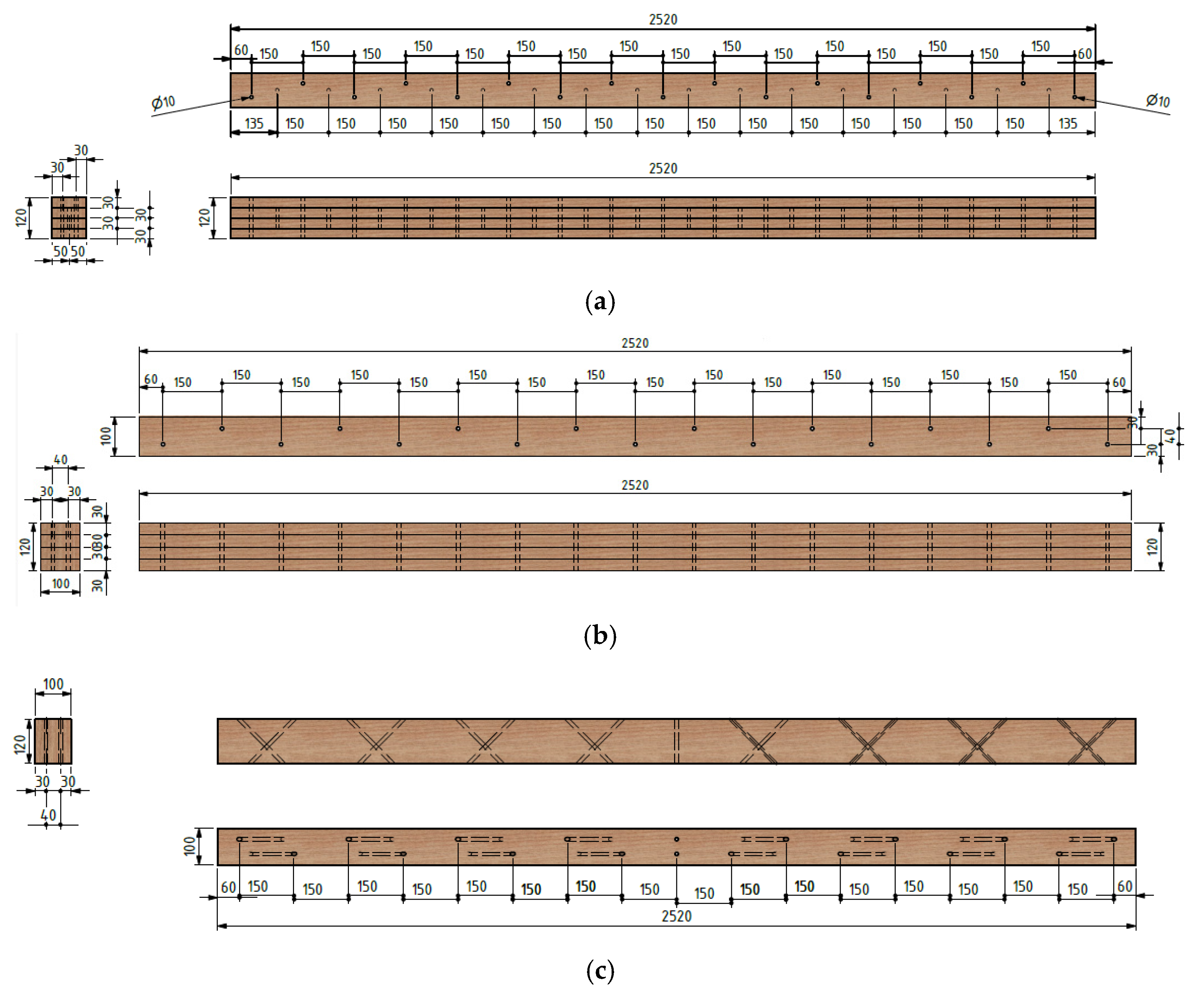
In the first series (marked as “90°*-pressed”), mechanically inserted wooden dowels of 60 mm length were installed between two lamellas, perpendicular to the longitudinal axis of the beam, as shown in Figure 2a. Care was taken to ensure that the dowels in adjacent rows of lamellas were installed in a staggered manner to avoid splitting. The same principle was used in the second series (marked as “90°*-welded”), where welded dowels were used. In the third series (marked as “90°-pressed”), mechanically inserted wooden dowels of 120 mm length were used, which were installed through all four lamellas, perpendicular to the longitudinal axis of the beam, as shown in Figure 2b. In the fourth series (marked as “45°-pressed”), mechanically inserted wooden dowels of 170 mm length were used, which were installed through all four lamellas, at an angle of 45° to the longitudinal axis of the beam, as shown in Figure 2c. For the last two series, a counterpart series with welded dowels was not made because the welding depth was not suitable for this type of connection. The dowel body is worn out by welding, and at depths greater than 80 mm it is not wide enough to touch the base wood and thus creates friction. This problem could be solved by forming conical dowels and holes. However, such a process would require the production of special tools and milling cutters.
The test standard specifies four-point bending over a test span of 18 times the height of the specimen. As a result, the specimen was intended to be supported over a test span of 2160 mm with point loads at 720 mm from each support. The total length of each specimen was slightly longer, at 21 times the height of the specimen, or 2520 mm.
The first phase was the selection of materials. Norway spruce (Picea abies) as softwood was selected for the base material. This species usually achieves structural grade C24 due to the climatic conditions in which it grows. The standard EN 338 [30] gives an average value of 11,000 MPa for the modulus of elasticity of C24 wood in the longitudinal direction, which is used as the primary substrate for the DLT elements in this study. Before the specimens were made, the material was conditioned to achieve the desired equilibrium moisture content. The conditioning procedure was the same as described in the previous chapter. After conditioning, the density of the wood of the base material was determined according to [13,14,15,16]. The procedure was the same as described in the previous chapter. The test results indicate a mean wood density of ρmean = 427 kg/m3 with an equilibrium moisture content of 12% (with a standard deviation of 13.57 and a coefficient of variation of 3.18%). It can be seen from the above data that the uniformity of wood quality has been achieved.
The wood was cut and shaped into lamellas, while the dowels had been previously made (for determination of its characteristics). The dowels are installed in the same way as mentioned in the previous chapter. The arrangement of dowels in each specimen is shown in Figure 2. After assembly, all specimens were conditioned to a moisture content of 12%.
As already mentioned, in order to avoid the possibility of wood splitting while inserting welded dowels, the axial spacing of the dowels is defined by the dimension of 15 d (where d is the nominal diameter of the dowel). Of course, this distance can be and will be much smaller in following testing series, up to at least 5 d or, which is recommended, up to 7 d [23]. Consequences of the larger spacement of dowels results in smaller stiffness of the DLT (as can be seen in Figure 3). The reason for this approach lies in the fact that the aim was to avoid possible failure of the lamellas by splitting along the line connecting the dowels, at the cost of less rigidity. This is exactly why well-structured flexural tests were obtained, which show consistent failure through the tension lamella.
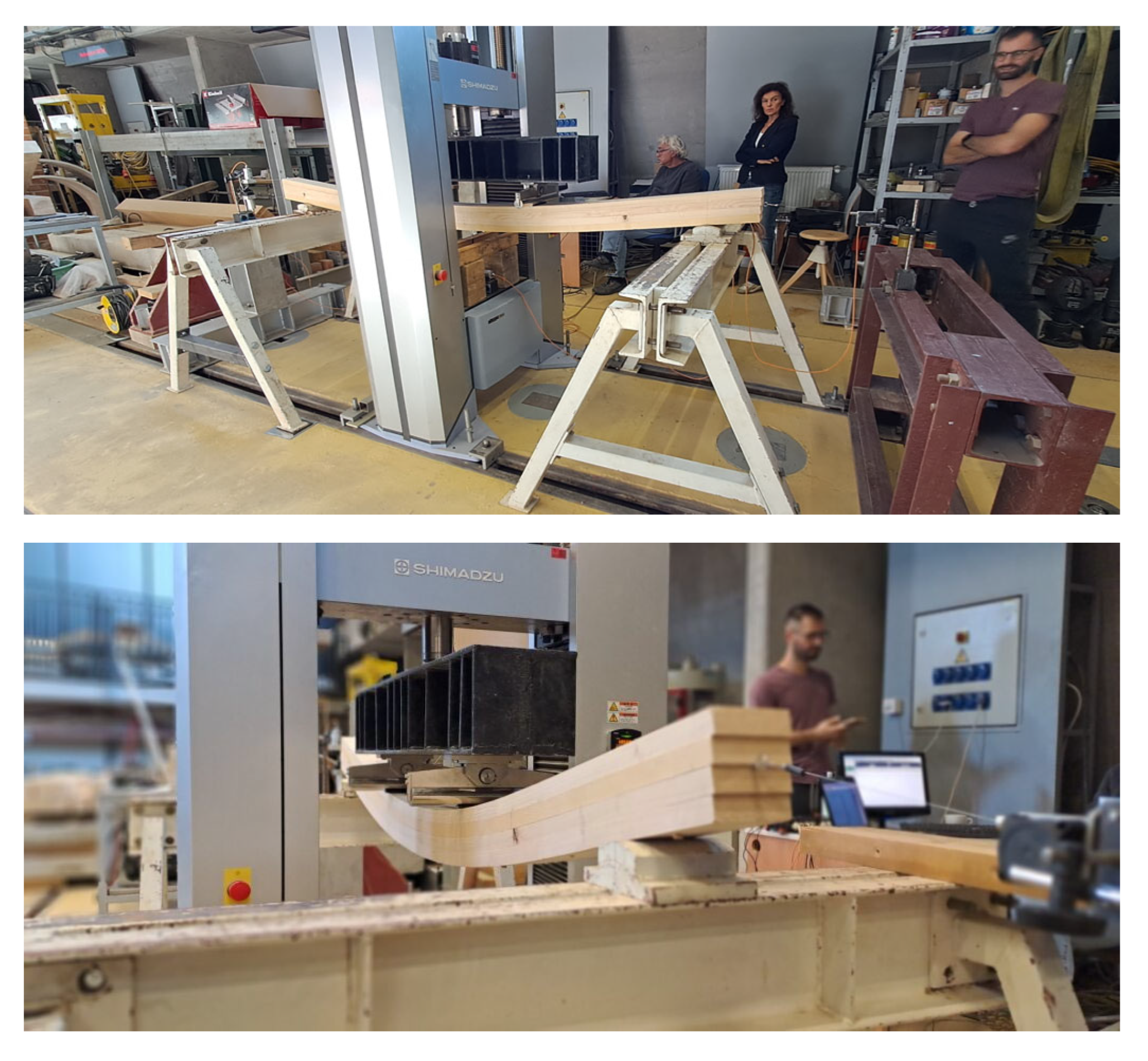
During the test, steel plates are positioned at the support points and load points as specified by EN 408 [29]. The load was applied according to the same standard at a constant rate of 15 mm/min for all specimens. The speed of load application is set at a value slightly lower than the maximum load speed allowed by the standard, which is equal to the value of 0.003 h mm/s (where h is the height of the cross-section of the beam). The device used to apply force to the specimens had an accuracy of within 1% for determining the force in the system for loads less than 10% of the load capacity and 0.1% for the failure load. Each specimen was loaded to approximately 10% of the load capacity, then the load was maintained at this level for an additional 30 s, after which the specimen was unloaded to start position, and then the specimen was loaded again to failure. The deformation at the mid-span, i.e., at the bottom of the beam cross-section, was measured by LVDT sensors, as well as horizontal displacement on a sliding bearing at the middle of the cross-section. In order to gain insight into the coupling efficiency, the horizontal displacement of the edge lamellas (upper and lower) on a fixed bearing was measured. The measuring instruments meet the accuracy requirements of 1%. Test settings are shown in Figure 3.

3. Results

3.1. Wooden Dowels Embedment Strength

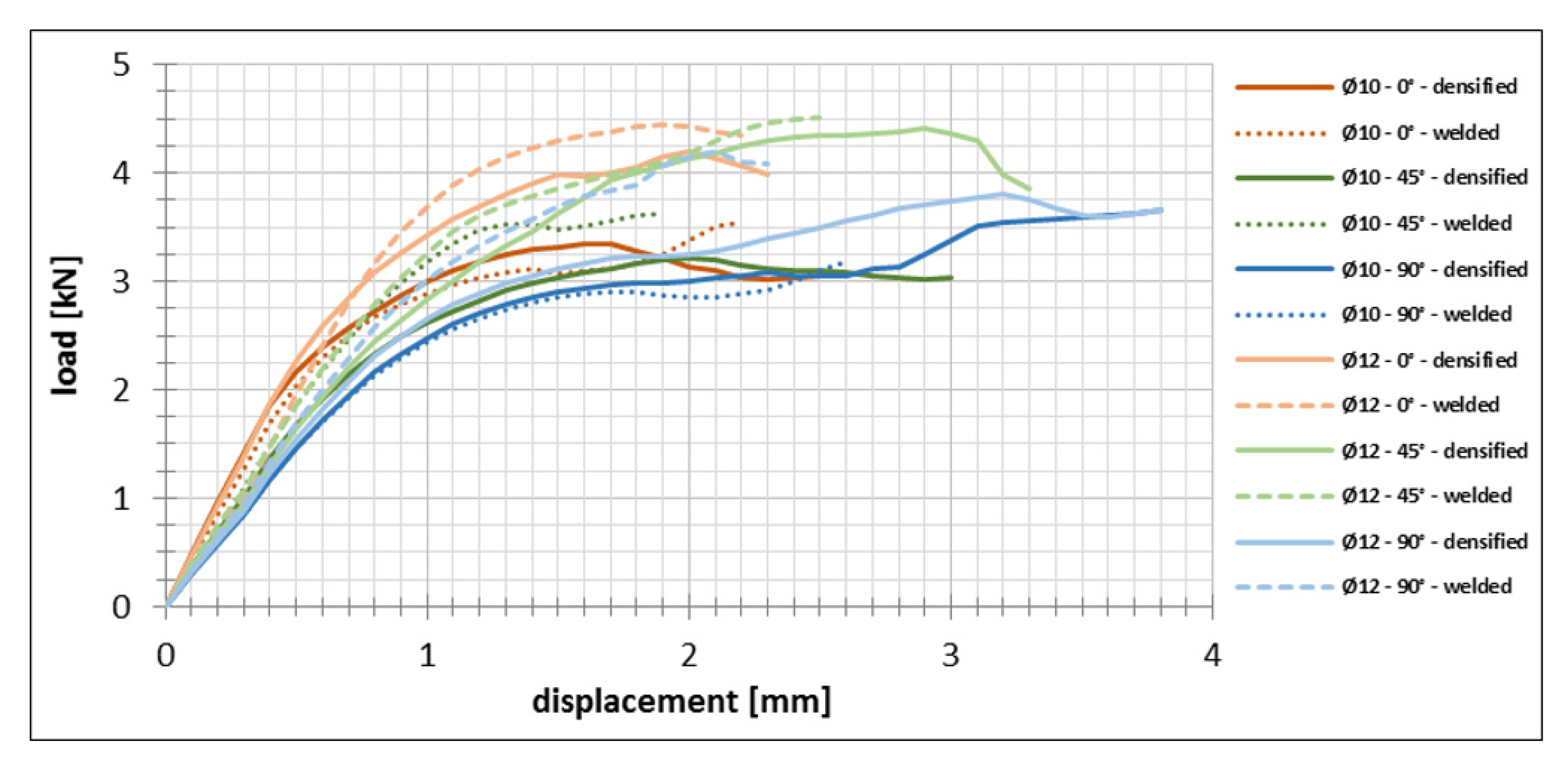
By processing the data generated during the tests, force–displacement curves were obtained. The curves are shown in Figure 4. The test showed the typical behavior of dowel joints according to Johansen’s theory for steel dowel-type fasteners. But the embedment strength values obtained for elements connected with wooden dowels did not reach desired threshold (the same conclusion can be drawn when comparing the results of the slip modulus).
The values are predicted by the analytical expression given in Eurocode 5 [23], i.e., by Equations (4) and (5) as follows:
fh,α,mean = 0.082 × (1 − 0.01 × d) × ρmean/(k90 × sin2α + cos2α),
where k90 = 1.35 + 0.015 × d for softwoods,
Kser,mean = ρmean1.5 × d/23,
(where fh,α, is the mean value of embedment strength depending on the angle α, α is the angle that the force makes with the direction of the wood fibers, and Kser,mean is the mean value of the slip modulus). In relation to theoretical assumptions there are certain deviations, and the tested values are not on the safe side. The higher theoretical values arise because the Eurocode 5 [23] equations were initially developed for steel dowel-type fasteners. Therefore, these equations should be considered more as comparative references, but not predictive models for wooden connectors. So, in case of the wooden dowels, there is a need for correction of expressions for the embedment strength given in Eurocode 5 [23]. Finally, the stiffness of the joints, i.e., the value of the slip modulus, was obtained. Data are given in Table 2 and compared to values calculated according to Eurocode 5 [23] (where the diameter of the fastener and the characteristic density of the wood are taken into account). This data will be the basis for further calculations, whether it is the calculation of the load-bearing capacity and deflection of the DLT beams or the load-bearing capacity of the dowels in the beam itself.
The difference in the behavior of welded and pressed dowels is more significant for smaller dowel diameters, where failure occurs more quickly in joints with welded dowels. The reason for this may be the wear of the drilled hole in the wood during welding of the dowel. However, the smaller difference, even more favorable in favor of the welded dowel, is for joints with larger dowel diameters. It can be concluded that with an increase in diameter and a better bond formed during welding due to a larger contact surface, the influence of lignin that binds the dowel to the basic ancient material would be much more effective.

3.2. Behavior of Dowel-Laminated Timber Beams

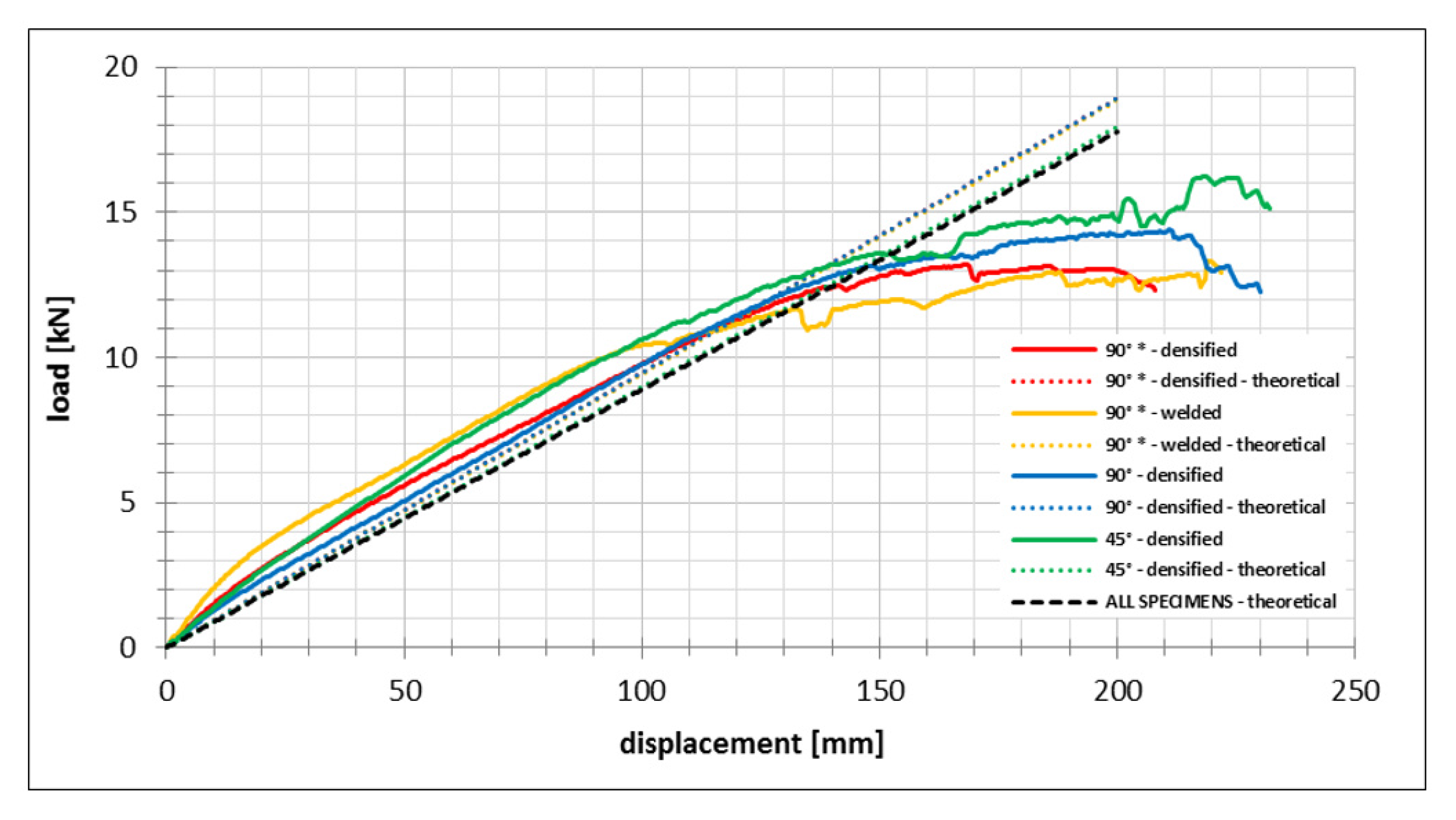
The tests provided a substantial amount of data on the beam behavior across multiple stages up to failure. All specimens failed equally, due to the fracture of the lowest lamella at the moment when the stress exceeded the bending strength of the wood. There is no significant difference in the achieved load-bearing capacity or behavior between the specimens with mechanically inserted and welded dowels when they were installed alternately through pairs of lamellas (failure shown on Figure 5).
However, it is important to note that tensile failure of the welded dowels occurred at the ends of some specimens. The cause of this is probably the weakening of the section due to welding. A slightly larger increase of 8% in load-bearing capacity was achieved in the case when the dowels were installed vertically through all lamellas. As expected, a more significant increase of 18% was achieved in the case when the dowels were installed at 45 degrees. In both cases, sliding of the dowel along the hole was observed in the case of large deformations, which is to be expected given that the dowels do not deform axially, but only transmit shear force between the lamellas.
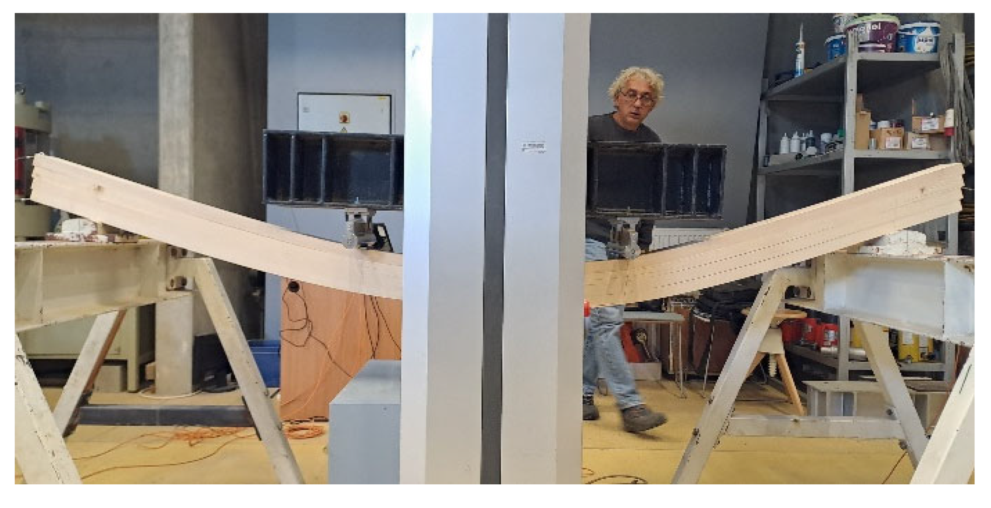
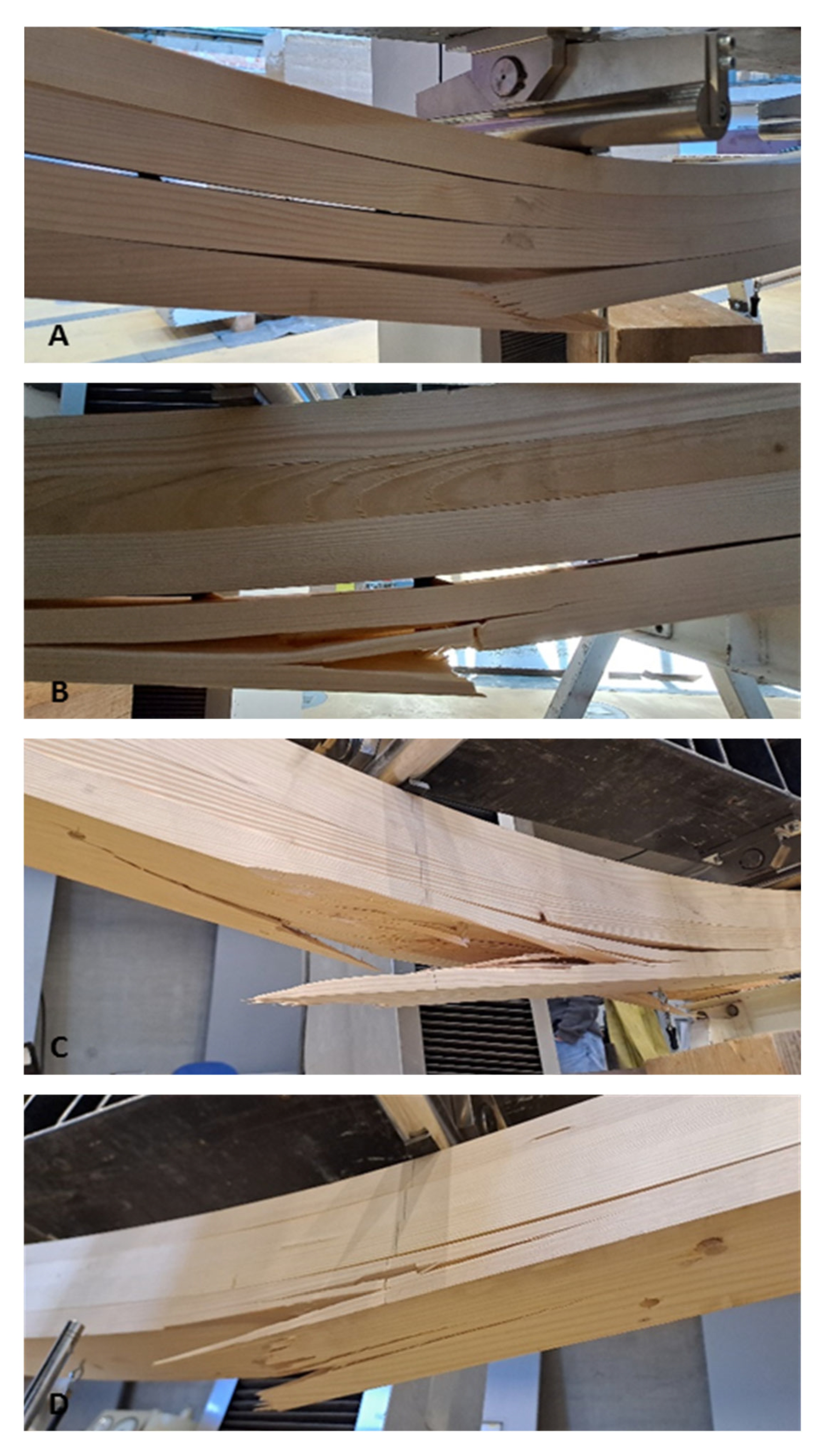
The characteristic failure modes are shown in Figure 6. Looking at the images of the tested beams, there is an impression that the deformation as well as relative displacements between the lamellas is too large for the achieved failure load. However, it should be emphasized that the goal of this research was not to obtain a beam stiff enough for classical use in construction, but to examine the behavior of the beam with different dowel settings. Therefore, the arrangement of dowels along the beam is somewhat less frequent to ensure that the wood does not split during installation or loading. It is logical that for larger diameters and a denser arrangement of dowels, the beam would certainly be stiffer.
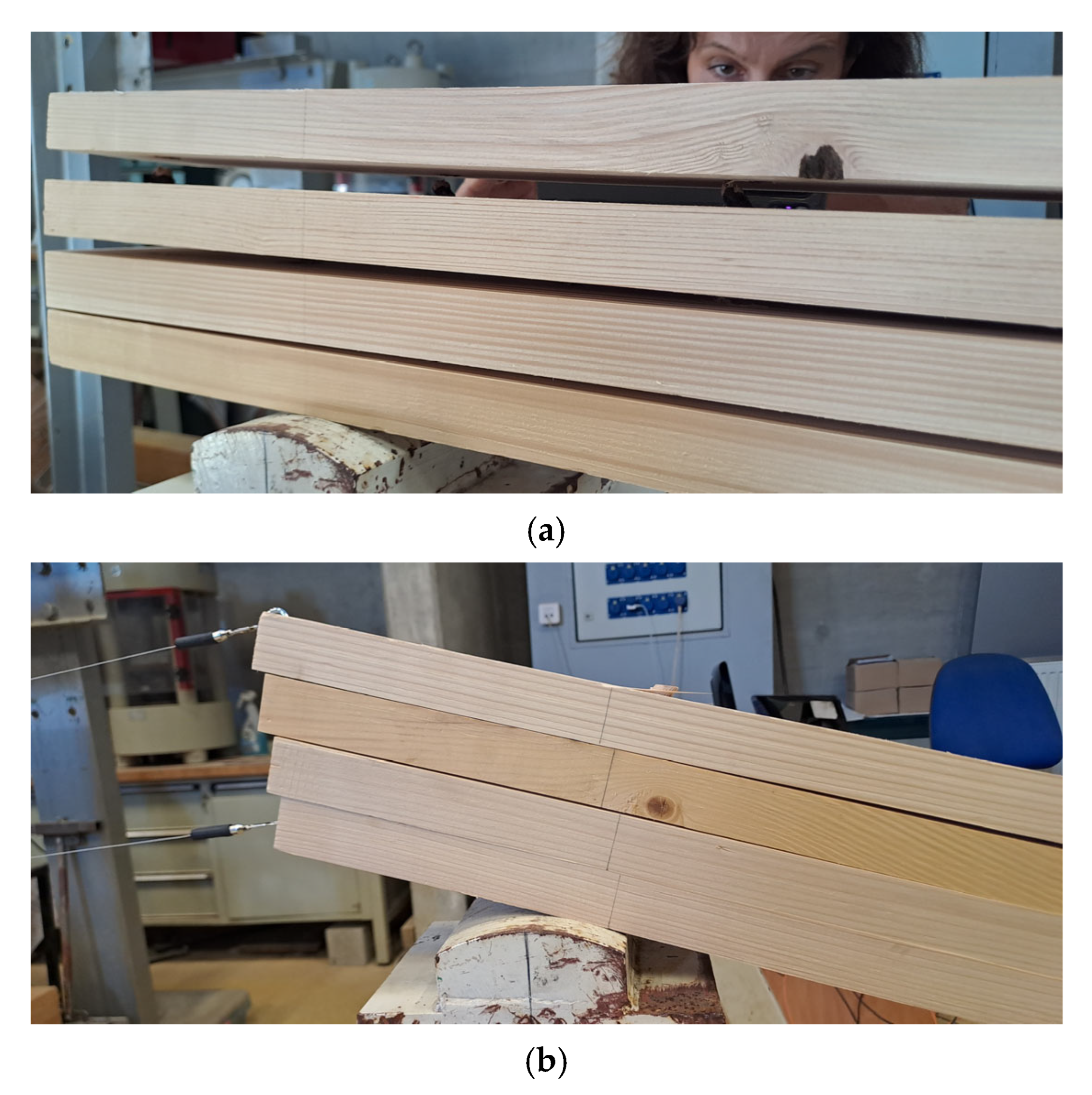
In all cases, large deformations resulted in significant delamination of the lamellae at the beams ends, as shown in Figure 7a. This is happening due to the fact that the dowels primarily resist shear, while tensile forces perpendicular to the lamellae, generated during deformation, are transmitted solely by friction between the lamellae (which is quickly overcome). The dowels in the fourth group of specimen types were more optimally oriented to resist these tensile forces, which explains the observed reduction in vertical separation. As shown in Figure 7b, in addition to the vertical separation, a significant horizontal displacement between the lamellae at the beams ends was observed at maximum deformation, the reason for which was previously explained.
By processing the data generated during the tests, force–displacement curves were obtained. The curves are shown in Figure 8. In the same picture, the diagrams of displacement forces according to theoretical calculations based on the “γ-method” are given. The elastic modulus E0,mean with a value of 11,000 MPa was used, while the force in relation to the displacement was calculated using the expression for the deformation of the beam loaded with a pair of forces symmetrically placed in relation to the center of the beam, given by Equation (6) as follows:
Δ = (F × a/24 × E × I) · (4 × a2 − 3 × L2)
where Δ is the vertical deformation, F the total force, L is the span of the beam, and a is the distance of the force input from the support.
The theoretical value of the stiffness EI required for the deflection calculation was calculated for two cases. In the first case, the slip modulus value was defined with respect to the values obtained in the dowels’ experimental study. Values obtained from dowel testing were adjusted with respect to the beam wood density. In the second case, the slip modulus was used according to the expression given in Eurocode 5 [23]. This expression for Kser,mean does not distinguish between the angle of force application or the type of dowel. Therefore, the value of the slip modulus as well as the beam stiffness is the same for all types of specimens. All data are shown in Table 3.
From data in Table 3, it is evident that the analytically obtained stiffness is the same for all types of specimens, while there are certain deviations between the specimens in the experimental values. However, these differences are not that significant. The stiffness of beams with diagonally installed dowels and beams with welded dowels is slightly higher, which indicates the positive influence of the type of dowel and the method of installation. Theoretical values are on the safe side, so it can be said that the standardized “γ-method” method is acceptable for the calculation of DLT beams. However, it should be noted that it is important to accurately determine the slip modulus as a parameter that significantly affects both the load-bearing capacity and deformability of beams.

4. Discussion

The aim of this work was primarily to determine the behavior of DLT beams phenomenologically, and not so much to compare the load-bearing capacity of the elements with other solutions or similar systems known in the literature. This very approach is quite lacking in the literature.
However, it is necessary to define how, compared to most research in the literature, the emphasis is placed on elements connected by welded studs. Typically, hardwood dowels have been used in the production of DLT products. However, in this study, mechanically inserted and welded dowels are used, as defined in the paper introduction. Tightly pressed dowels have shown good properties in shear testing. They also have the property of shape recovery or elasticity, which means that they will expand over time, resulting in a strong bond that can be useful a characteristic in many applications in wood structural engineering. Such proven superior structural properties are also environmentally friendly, making them a good alternative to metal fasteners [12]. On the other hand, welded dowels are effective due to the temperature-induced softening and flowing of some amorphous cells interconnecting wood material. The consequences are high-performing mechanically inserted dowels of the bonded interface. Wood species, relative diameter, difference between the dowel and the receiving hole, and dowel insertion are the parameters that yield significant strength differences.
The embedment strength follows the expected trend, increasing with element density and decreasing as the load direction deviates from the grain direction. Welding dowels did not significantly influence the embedment strength in comparison to mechanically pressed dowels for diameters of 10 and 12 mm. It should be further investigated whether welding contributes more significantly to dowels with larger diameter. The experimental results indicate that the embedment strength calculation provided in Eurocode 5 [23] is not suitable for applications involving wooden dowels. The results show lower load-bearing capacities, and therefore, the analytical expression given in by Equations (4) and (5) needs to be adjusted. One of the reasons for the overestimated embedment strength could certainly be the lower stiffness of wood versus steel. Direct use of metal-fastener expressions overestimates embedment strength, so calibration coefficients are required for wooden dowels. It is also worth noting that these differences are in most cases small and need to be considered to define them for a large number of specimens when the statistical picture is clearer. Providing statistical variability and referencing measured ranges for DLT beam systems would make the discussion more credible.
Testing of the DLT beams demonstrated that the connection parameters have a significant impact on beam behavior. A high degree of lamella composite action can be achieved using larger-diameter dowels at smaller spacing. Furthermore, it was shown that connecting fewer lamellae does not result in a substantially lower load-bearing capacity compared to connecting all lamellae with a single dowel, which can be particularly advantageous when designing beams of bigger dimensions. The orientation of the dowels determines whether they transfer only shear forces or a combination of shear and axial forces. The 18% performance improvement with dowels installed at a 45° angle to the lamella fibers is a significant indicator, as previously mentioned. Precisely this position of the dowel results in an increase in the tensile load capacity of the joint of the lamella and the dowel due to friction, which prevents delamination but also increases the shear capacity due to the larger cutting surface. The welding process generally increases the dowel pull-out resistance, due to the cohesion that occurs between the base and the dowel material. However, as mentioned before, welding consumes the cross-section of the dowel, and for smaller diameters, the cohesion between materials is greater than the tensile resistance of the dowel. In this case, the dowels on the edge segments of the beam, where the greatest stress occurs, fail, which causes separation of lamellas.
The “γ-method” proved to be a satisfactory approach for calculating the effective stiffness of the beams, although the results are conservative. The application of the “γ-method” seems reasonable for relative comparison, but the assumption of an identical slip modulus in all beam configurations seems at first sight to be unrealistic. Therefore, it seems that it is necessary to adjust the slip modulus to account for additional connection parameters, thereby obtaining more realistic estimates of lamella composite action. However, it is necessary to emphasize that the theoretical basis is such that the behavior for all beam configurations should be the same, which is what was attempted to be investigated. Furthermore, this research indicates minor deviations in behavior between individual beam types. So, the question is what would happen for a large number of specimens and whether the behavior trend would indicate that the theoretical assumption is confirmed.

5. Conclusions

The experimental results indicate that it is possible to achieve a high degree of composite action using dowel-laminated timber for the beams. This degree of efficiency could be further enhanced for even more competitive performance by using more dowels in multiple rows in the case of larger cross-section elements. The contribution of wood welding is presented, and it is concluded that there is no significant difference for smaller dowel diameters in comparison to mechanically inserted dowels. With smaller diameters, welded dowels perform worse due to the wasted section. Influence of melted lignin film is only evident for larger diameters where the friction between the wood parts when pressed dowel is used is less than the cohesive force created by welding the dowel. The positioning of the wooden dowel inside the beam does not significantly affect its load-bearing capacity and deformability, except for the dowels which are installed diagonally at an angle of 45° to the fibers of the lamella. In that case, a more significant difference in the increase in stiffness of approximately 20% is visible, which is most likely caused by a larger contact surface at the contact between the lamella and the dowel. Therefore, for assembly simplicity, dowels can be used between individual lamellas, rather than through the entire cross-section. This is especially important for beams with large cross-sections. The standardized “γ-method” performed to be satisfactory for calculation of deflection and stresses in beam. However, for final application, which also includes the calculation of load-bearing capacity, it is necessary to adapt the standardized expressions for metal fasteners, especially regarding the embedment strength and the slip modulus where tests showed lower values than theoretical. The greatest limitation of this study is precisely the small number of samples, which does not allow creating a complete statistical picture that could define the change in the calculation expressions with certainty.
The objectives of further research in this study are to investigate the application of the behavior of joints and beams with larger diameter dowels, optimization of dowel spacing, as well as the use of densified dowels and hardwood lamellas. For a complete phenomenological analysis, it is necessary to define the yield moment for different types of wooden dowels, and further investigation of hydro-thermomechanical and creep/relaxation behavior deserves attention.

Author Contributions

Conceptualization, V.R. and J.B.; methodology, V.R., J.B. and N.P.; software, N.P.; validation, J.B. and B.Z.; formal analysis, J.B. and B.Z.; investigation, J.B., B.Z. and N.P.; resources, V.R. and J.B.; data curation, V.R.; writing—original draft preparation, J.B. and B.Z.; writing—review and editing, V.R. and N.P.; visualization, J.B. and N.P.; supervision, V.R.; project administration, V.R., J.B. and N.P.; funding acquisition, V.R. All authors have read and agreed to the published version of the manuscript.

Funding

This research is part of the scientific research project HRZZ IP-2022-10-1800 “ECO-WOOD Structures”, financed by the Croatian Science Foundation (CSF).

Data Availability Statement

The datasets generated and/or analyzed during this research are not publicly available but are available from the corresponding author on reasonable request.

Acknowledgments

We would like to thank Ivica Župčić and Ivan Žulj from the Faculty of Forestry and Wood Technology, University of Zagreb, for the effort in making the specimens. Also, special thanks to Jurko Zovkić and Damir Varevac from the Faculty of Civil Engineering and Architecture Osijek, Josip Juraj Strossmayer University of Osijek, for their hospitality and assistance in laboratory research. Without this group of experienced scientists, this research would certainly not have been as feasible and successful.

Conflicts of Interest

The authors declare no conflicts of interest. The funders had no role in the design of the study, in the collection, analyses, or interpretation of data, in the writing of the manuscript, or in the decision to publish the results.

References

  1. Han, L.; Kutnar, A.; Sandak, J.; Šušteršič, I.; Sandberg, D. Adhesive-and Metal-Free Assembly Techniques for Prefabricated Multi-Layer Engineered Wood Products: A Review on Wooden Connectors. Forests 2023, 14, 311. [Google Scholar] [CrossRef]
  2. Sotayo, A.; Bradley, D.; Bather, M.; Sareh, P.; Oudjene, M.; El-Houjeyri, I.; Harte, A.M.; Mehra, S.; O’Ceallaigh, C.; Haller, P.; et al. Review of state of the art of dowel laminated timber members and densified wood materials as sustainable engineered wood products for construction and building applications. Dev. Built Environ. 2020, 1, 100004. [Google Scholar] [CrossRef]
  3. Puettmann, M.E.; Wilson, J.B. Gate-to-gate life-cycle inventory of glued-laminated timbers production. Wood Fiber Sci. 2005, 37, 99–113. [Google Scholar]
  4. Venkatarama-Reddy, B.V. Sustainable building technologies. Curr. Sci. 2024, 87, 899–907. [Google Scholar]
  5. Ramage, M.H.; Burridge, H.; Busse-Wicher, M.; Fereday, G.; Reynolds, T.; Shah, D.U.; Wu, G.; Yu, L.; Fleming, P.; Densley-Tingley, D.; et al. The wood from the trees: The use of timber in construction. Renew. Sustain. Energy Rev. 2017, 68, 333–359. [Google Scholar] [CrossRef]
  6. Niu, Y.; Rasi, K.; Hughes, M.; Halme, M.; Fink, G. Prolonging life cycles of construction materials and combating climate change by cascading: The case of reusing timber in Finland. Resour. Conserv. Recycl. 2021, 170, 105555. [Google Scholar] [CrossRef]
  7. Derikvand, M.; Hosseinzadeh, S.; Fink, G. Mechanical Properties of Dowel Laminated Timber Beams with Connectors Made of Salvaged Wooden Materials. J. Archit. Eng. 2021, 27, 04021035. [Google Scholar] [CrossRef]
  8. Derikvand, M.; Fink, G. Potential of reusing salvaged wooden materials in fabricating structural dowel laminated timber. In Proceedings of the World Conference on Timber Engineering 2023—WCTE 2023, Oslo, Norway, 19–22 June 2023; pp. 1–6. [Google Scholar]
  9. Aloisio, A.; Wang, Y.; Crocetti, R.; Nyrud, A.Q.; Tomasi, R. Mechanical performance of pure-wood moment-resisting ridge joints with plywood gussets and wooden dowels. Eng. Struct. 2025, 334, 120271. [Google Scholar] [CrossRef]
  10. O’Ceallaigh, C.; Conway, M.; Mehra, S.; Harte, A.M. Numerical investigation of reinforcement of timber elements in compression perpendicular to the grain using densified wood dowels. Constr. Build. Mater. 2021, 288, 122990. [Google Scholar] [CrossRef]
  11. Conway, M.; Mehra, S.; Harte, A.M.; O’Ceallaigh, C. Densified wood dowel reinforcement of timber perpendicular to the grain: A pilot study. J. Struct. Integr. Maint. 2021, 6, 177–186. [Google Scholar] [CrossRef]
  12. O’Ceallaigh, C.; Harte, A.M.; McGetrick, P.J. Numerical examination of the behaviour of dowel laminated timber elements utilising compressed wood dowels. In Proceedings of the World Conference on Timber Engineering 2023—WCTE 2023, Oslo, Norway, 19–22 June 2023; pp. 1–9. [Google Scholar]
  13. Xu, B.-H.; Zhang, S.-D.; Zhao, Y.-H.; Bouchaïr, A.; Zhang, B. Mechanical Properties of Adhesive-Free Cross-Laminated Timber. J. Struct. Eng. 2022, 148, 04022135. [Google Scholar] [CrossRef]
  14. Bruzzone, G.; Godoy, D.; Quagliotti, S.; Arrejuria, S.; Böthig, S.; Moya, L. Experimental Investigation on Dowel Laminated Timber Made of Uruguayan Fast-Grown Species. Forests 2023, 14, 2215. [Google Scholar] [CrossRef]
  15. El-Houjeyri, I.; Thi, V.-D.; Oudjene, M.; Khelifa, M.; Rogaume, Y.; Sotayo, A.; Guan, Z. Experimental investigations on adhesive free laminated oak timber beams and timber-to-timber joints assembled using thermo-mechanically compressed wood dowels. Constr. Build. Mater. 2019, 222, 288–299. [Google Scholar] [CrossRef]
  16. Teodorescu, I.; Pereira, B.; Aquino, C.D.; Branco, J.M. Experimental evaluation of dowel-type timber joints with wooden dowels. Proc. Inst. Civ. Eng. Struct. Build. 2020, 173, 927–938. [Google Scholar] [CrossRef]
  17. Khan, I.U.; Subhani, M.; Ghabraie, K.; Ashraf, M. Exploring and refining testing approaches for hardwood dowels under axial and flexural loading: An experimental and numerical study. Wood Mater. Sci. Eng. 2025, 1–23. [Google Scholar] [CrossRef]
  18. Tomasi, R.; De Santis, Y.; Aloisio, A.; Crocetti, R.; Sæby, V.H.; Nyrud, A.Q. Experimental and analytical investigation on timber connections with beech, birch and laminated densified wooden dowels. Constr. Build. Mater. 2025, 494, 14269. [Google Scholar] [CrossRef]
  19. Župčić, I.; Vlaović, Z.; Domljan, D.; Grbac, I. Influence of Various Wood Species and Cross-Sections on Strength of a Dowel Welding Joint. Drv. Ind. 2014, 65, 121–127. [Google Scholar] [CrossRef]
  20. Gedara, A.K.A.; Chianella, I.; Endrino, J.L.; Zhang, Q. Adhesiveless bonding of wood—A review with a focus on wood welding. BioResources 2021, 16, 6448–6470. [Google Scholar] [CrossRef]
  21. Bocquet, J.F.; Pizzi, A.; Despres, A.; Mansouri, H.R.; Resch, L.; Michel, D.; Letort, F. Wood joints and laminated wood beams assembled by mechanically–welded wood dowels. J. Adhes. Sci. Technol. 2007, 21, 301–317. [Google Scholar] [CrossRef]
  22. O’Loinsigh, C.; Oudjene, M.; Ait–Aider, H.; Fanning, P.; Pizzi, A.; Shotton, E.; Meghlat, E.-M. Experimental study of timber-to-timber composite beam using welded-through wood dowels. Constr. Build. Mater. 2012, 36, 245–250. [Google Scholar] [CrossRef]
  23. EN 1995-1-1:2004+AC:2006+A1:2008; Eurocode 5: Design of Timber Structures. CEN: Bruxelles, Belgium, 2008.
  24. Gutkowski, R.; Brown, K.; Shigidi, A.; Natterer, J. Laboratory tests of composite wood-concrete beams. Constr. Build. Mater. 2008, 22, 1059–1066. [Google Scholar] [CrossRef]
  25. EN 1380:2009; Timber Structures—Test Methods—Load Bearing Nails, Screws, Dowels and Bolts. CEN: Bruxelles, Belgium, 2009.
  26. ISO 3129:2019; Wood—Sampling Methods and General Requirements for Physical and Mechanical Testing of Small Clear Wood Specimens. International Organization for Standardization: Geneva, Switzerland, 2019.
  27. ISO 13061:2014; Physical and Mechanical Properties of Wood—Test Methods for Small Clear Wood Specimens—Part 1—Determination of Moisture Content for Physical and Mechanical Tests. International Organization for Standardization: Geneva, Switzerland, 2014.
  28. EN 384:2016+A2:2022; Structural Timber—Determination of Characteristic Values of Mechanical Properties and Density. CEN: Bruxelles, Belgium, 2022.
  29. EN 408:2010+A1:2012; Timber Structures—Structural Timber and Glued Laminated Timber—Determination of Some Physical and Mechanical Properties. CEN: Bruxelles, Belgium, 2012.
  30. EN 338:2016; Structural Timber—Strength Classes. CEN: Bruxelles, Belgium, 2016.
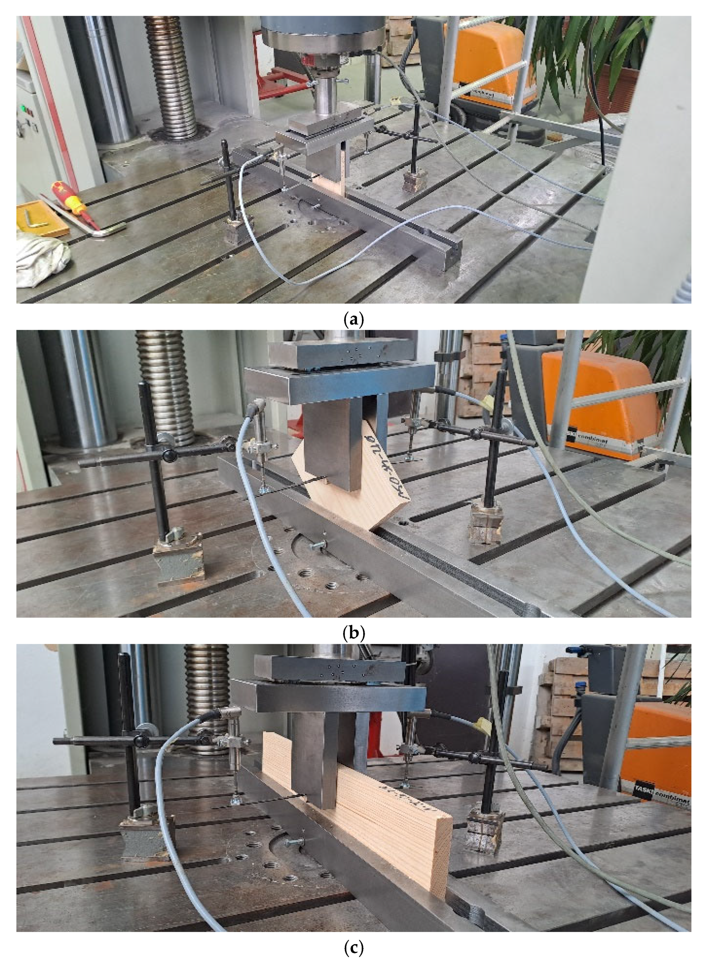
Figure 1. Testing specimens on embedment strength: Specimens loaded parallel to the grain (a), at an angle of 45° to the grain (b), and perpendicular to the grain (c).
Forests 16 01748 g001
Figure 2. Specimens type for DLT beams experimental investigation where dowels are installed between two lamellas, perpendicular to the longitudinal axis of the beam (a); through all four lamellas, perpendicular to the longitudinal axis of the beam (b); and through all four lamellas, at an angle of 45° to the longitudinal axis of the beam (c).
Forests 16 01748 g002
Figure 3. Test settings for dowel-laminated timber beams.
Forests 16 01748 g003
Figure 4. Averaged force–displacement curves for tested specimens.
Forests 16 01748 g004
Figure 5. Characteristic failure of beam specimen with dowels installed alternately through the lamellas.
Forests 16 01748 g005
Figure 6. Characteristic failure of beam specimen with mechanically inserted dowels installed alternately through the lamellas (A), welded dowels installed alternately through the lamellas (B), mechanically inserted dowels installed vertically through the all lamellas (C), and mechanically inserted dowels with dowels installed at a 45° angle through the all lamellas (D).
Forests 16 01748 g006
Figure 7. Large deformation during beam failure causes significant delamination of the lamellae at the beam end (a) and a significant horizontal displacement between the lamellae at the beam end (b).
Forests 16 01748 g007
Figure 8. Averaged force–displacement curves for tested specimens with curves for theoretical behavior of DLT beams.
Forests 16 01748 g008
Table 1. Dimensions of specimens for determination of wooden dowels characteristics.
Type of SpecimenDimensions of the Lamellae That Makes Specimen
Dowel Diameter
[mm]
Force Angle
[°]
Length
[mm]
Heigh
[mm]
Thickness
[mm]
10010014015
45140 (198)14015
9040010015
12010016818
45168 (238)16818
9048010018
Table 2. Comparison of tested and theoretical for wooden dowels characteristics data.
Type of SpecimenTheoretical Data/Tested Data
Dowel Diameter
[mm]
Force Angle
[°]
Dowel Installation Typefh,α,mean
[N/mm2]
Kser,mean
[N/mm]
100pressed29.52/22.273479/4789
welded31.75/23.623881/4260
45pressed27.72/21.374423/3389
welded33.39/24.115846/3698
90pressed21.20/24.343888/2949
welded21.44/21.213956/2927
120pressed26.34/19.463639/4674
welded26.09/20.593588/3797
45pressed22.31/20.453901/3285
welded22.46/20.83941/3741
90pressed16.74/17.583489/3106
welded18.92/19.444190/3393
Table 3. Comparison of tested and theoretical behavior data for DLT beams.
Type of SpecimenTested DataTheoretical Data
Kser,mean
[N/mm]
Fmax
[kN]
EImean
[Nmm2 × 1010]
Kser,mean
[N/mm]
EImean
[Nmm2 × 1010]
90°*-pressed434213.324.04538363.384/3.180
90°*-welded430913.314.85338363.371/3.180
90°-pressed434214.383.78338363.384/3.180
45°-pressed390716.214.19738363.209/3.180
Disclaimer/Publisher’s Note: The statements, opinions and data contained in all publications are solely those of the individual author(s) and contributor(s) and not of MDPI and/or the editor(s). MDPI and/or the editor(s) disclaim responsibility for any injury to people or property resulting from any ideas, methods, instructions or products referred to in the content.