Article

Mechanical Behaviour of Leeward Lateral Roots During Tree Overturning

by
Xingyu Zhang
1,2,*,
Jonathan Knappett
3,*,
Tian Zhang
1,
Zhiwen Zheng
2,4,
Teng Liang
5,
Shitang Ke
1,
Matteo Ciantia
3 and
Anthony Leung
6
1
Department of Civil and Airport Engineering, Nanjing University of Aeronautics and Astronautics, Liyang 213300, China
2
South China Field Scientific Observation and Research Station for Climate-Driven Landslide Risk, Ministry of Natural Resources, Guangzhou 510599, China
3
School of Science and Engineering, University of Dundee, Dundee DD1 4HN, UK
4
Guangdong Geological Environment Monitoring Station, Guangzhou 510599, China
5
Institute of Hypergravity Science and Technology, Zhejiang University, Hangzhou 310058, China
6
State Key Laboratory of Climate Resilience for Coastal Cities, Department of Civil and Environ-Mental Engineering, The Hong Kong University of Science and Technology, Hong Kong SAR, China
*
Authors to whom correspondence should be addressed.
Forests 2025, 16(11), 1692; https://doi.org/10.3390/f16111692
Submission received: 6 October 2025 / Revised: 2 November 2025 / Accepted: 4 November 2025 / Published: 6 November 2025
(This article belongs to the Section Forest Ecology and Management)

Abstract

The overturning resistance of trees under lateral loads depends on the interaction between their root system and the surrounding soil, with leeward lateral roots being particularly important. This study presents a parametric investigation into the behaviour of leeward lateral roots during tree overturning using the finite element method (FEM) based on a beam-on-nonlinear-Winkler-foundation (BNWF) approach. The model efficiently simulates large root–soil deformations using non-linear p-y connectors, the properties of which were calibrated against 2D plane-strain continuum FEM simulations and validated against analytical solutions for pipeline bearing capacity (an analogous problem). Simulations varied in root diameter, length, and material properties. A critical root length was identified, beyond which further increases in length do not enhance the root’s contribution to tree moment capacity, defining an optimal root length for peak resistance. The study further demonstrates that moment capacity is profoundly more sensitive to root diameter than to length. Initial rotational stiffness, which is highly relevant to non-destructive field-based winching tests, was also found to be primarily controlled by diameter and independent of length for most practical cases. A direct comparison between leeward and windward roots under specified rotation conditions confirmed the greater mechanical contribution of leeward roots to anchorage, which is consistent with field observations.

1. Introduction

The roots of vegetation serve as natural soil anchors, offering a sustainable nature-based solution (NBS) for mitigating geotechnical and hydrological risks. Their stabilising function is achieved through two primary mechanisms: direct mechanical reinforcement of the soil matrix [1,2] and modulation of regional hydrological patterns by regulating groundwater flow [3,4]. The anchorage capacity of trees under overturning forces is a critical research domain within forestry, where windstorms, debris flows, and landslides pose recurrent threats, potentially leading to widespread ecosystem degradation and loss of vegetation [5,6]. Understanding and enhancing tree stability through targeted forest management practices is, therefore, critical for building resilience against the increasing frequency of extreme weather events under climate change [7]. Effective forest management strategies that account for root system architecture and soil–root interactions can significantly improve stand stability and reduce vulnerability to windthrow. The role of tree anchorage is equally significant in civil engineering. Windthrow events on slopes can initiate landslides [8] or damage critical infrastructure, such as railway overhead power lines. Conversely, trees can be strategically employed as economical natural barriers to protect assets from wind forces or debris flows [9]. This is particularly pertinent in regions frequently subjected to extreme weather events, such as South China, where the Guangdong Province annually experiences significant rainfall and powerful typhoons [10]. These conditions trigger numerous shallow landslides, causing substantial economic losses and posing threats to human safety. On these slopes, the interaction between vegetation and the soil matrix becomes a critical line of defence against failure. Consequently, a detailed investigation into the mechanical behaviour of these root–soil interactions is essential for understanding slope stability mechanisms and for developing effective nature-based mitigation strategies integrated into forest management plans in such hazard-prone areas.
Field-based winching (or pulling) tests have been widely employed to study tree anchorage, wherein a force is applied diagonally to the stem, resulting in rotation of the trunk, to gradually overturn the tree and quantify the resistance provided by the root system [11,12,13]. To achieve greater control over variables such as root architecture and soil conditions, an increasing number of studies have utilised scaled physical models, reconstructed from field root systems [14,15], under either 1 g conditions [16,17,18] or enhanced gravity conditions in a geotechnical centrifuge [19]. While such testing, whether in the field or the laboratory, can determine the overall overturning moment capacity and identify root breakage patterns, it typically cannot capture the internal stress distribution within the root system or quantify the individual contribution of each root during the overturning process. Numerical simulations, particularly the finite element method (FEM), have been adopted to overcome these limitations. While studies have developed 3D models of root systems to simulate the overturning process [20,21], conventional FEM struggles with the large soil–root displacements encountered before peak moment capacity is reached, often leading to mesh distortion and reduced accuracy. Although advanced techniques like the material point method (MPM) [22] can handle large deformations, they require modelling vast volumes of soil with continuum elements. This leads to a mesh that is often too coarse relative to the root size, compromising accuracy and computational efficiency, or making models too large to run in practical scenarios. These limitations highlight the need for improved modelling strategies for root–soil interaction.
Considering the tree-overturning problem shown schematically in Figure 1, under external lateral loading, the root system experiences complex load transfers. Roots on the windward side are primarily pulled up through the soil and are subject to tension, while those on the leeward side are pushed into the soil and subjected to compression. This asymmetrical architecture of the root system is particularly evident in plants growing on steep slopes, where mechanical forces result in preferential lateral root emergence and elongation in both up-slope and down-slope directions to enhance stability [23]. While previous research has comprehensively summarised the state-of-the-art in root reinforcement modelling [24,25], predominantly addressing root behaviour under basal shear [26,27] and pull-out loading [28,29], the specific mechanical behaviour of leeward lateral roots during tree overturning remains less quantified. This paper aims to conduct a parametric study, numerically simulating leeward lateral roots during the tree-overturning process, to understand their contribution to tree rotational behaviour and the effects of root length, diameter, and mechanical properties (i.e., species) on moment resistance and rotational stiffness. A beam-on-non-linear-Winkler-foundation (BNWF) approach, using non-linear p-y curves calibrated against simple 2D plane-strain continuum finite element (FE) models, was employed, which has significant advantages in computational efficiency compared to 3D FEM and MPM approaches. This approach provides a robust framework for analysing root–soil interaction and yielding vital quantitative insights for optimising forest management, designing nature-based slope stabilisation methods, and advancing reliability-based models for windthrown risk assessment.

2. Materials and Methods

2.1. General Description of Modelling Methodology

The numerical simulations were conducted using the finite element programme ABAQUS 2020, implementing a beam-on-nonlinear-Winkler-foundation (BNWF) approach. As shown in Figure 2, the leeward lateral roots were idealised as straight, cylindrical structural members with a constant diameter ( d r ) and length ( l r ). These roots were discretized using 1 mm-long deformable 3D beam elements capable of capturing both shear and flexural deformation. The loading condition simulated the rotational displacement imposed on the trunk during tree overturning, with the model root rotating anticlockwise about its connection point to the stump under displacement-controlled conditions. To understand the generalised leeward lateral behaviour, no attached vertical sinker roots were attached, though their additional transverse point-anchorage resistances could be incorporated through modified connector properties in the BNWF model, where they connect to the lateral root for application to specific root architectures. A linear elasto-plastic brittle material model was used to model the stress–strain behaviour of the root. A series of fixed, rigid vertical beams, which sat at a close and uniform vertical offset (i.e., 0.0004 mm) from the discrete nodes along the root, was established to represent the stationary ground. Non-linear p-y connectors were then connected transversely between the root and the fixed beams to capture the root–soil interaction. The behaviour of these connectors was parametrised from 2D plane-strain FEM simulations and validated against analytical solutions for pipeline bearing capacity as reported by ref. [30]. Connectors were created to represent the resistance of the soil beneath the root, with the detailed modelling method described in a subsequent section. Compared with the traditional p-y method for small deformations (e.g., as used for lateral loading of piled foundations [31]), where the springs are considered to remain perpendicular to the original position of the root before loading, in the present study the connector force always acted perpendicular to the displaced root axis, which enabled large deformations to be captured [32]. This was achieved by using a connector element with the Cartesian type and a rotating local reference frame in ABAQUS. A hinged connection with fixed conditions in the horizontal and vertical directions was incorporated at the loading point (connection to the trunk) at the end of the root to prevent any unwanted movement during rotation (clockwise as shown in Figure 2, applied through displacement control and representing the rotational movement of the trunk under lateral load). Other than at this point, movement of the root was unrestrained, other than by the connector reactions.

2.2. Model Set-Up

The simulations that were conducted and the corresponding input parameters are summarised in Table 1. A 60 mm diameter root that was 900 mm in length (simulation A-02) was first simulated to be representative of one from a digitised field root system reported by existing research [33], where lateral roots were buried on average at 130 mm from the ground surface to the root centreline (here denoted as z r ). All simulations in this study were considered at this burial depth, with varying diameter and length. Root lengths were varied from 900 to 120 mm in series A (simulations A-01 to A-07), while root diameters were varied from 60 to 6 mm between different series (i.e., simulations A to F) to cover a wide range of slenderness ratios ( l r / d r ) between 1.3 and 15. According to experimental tests of single roots in the literature, the tensile strength T r and the Young’s modulus E r of roots typically demonstrate a power law trend with diameter d r [34,35]:
T r   =   α T d r β T
E r = α E d r β E
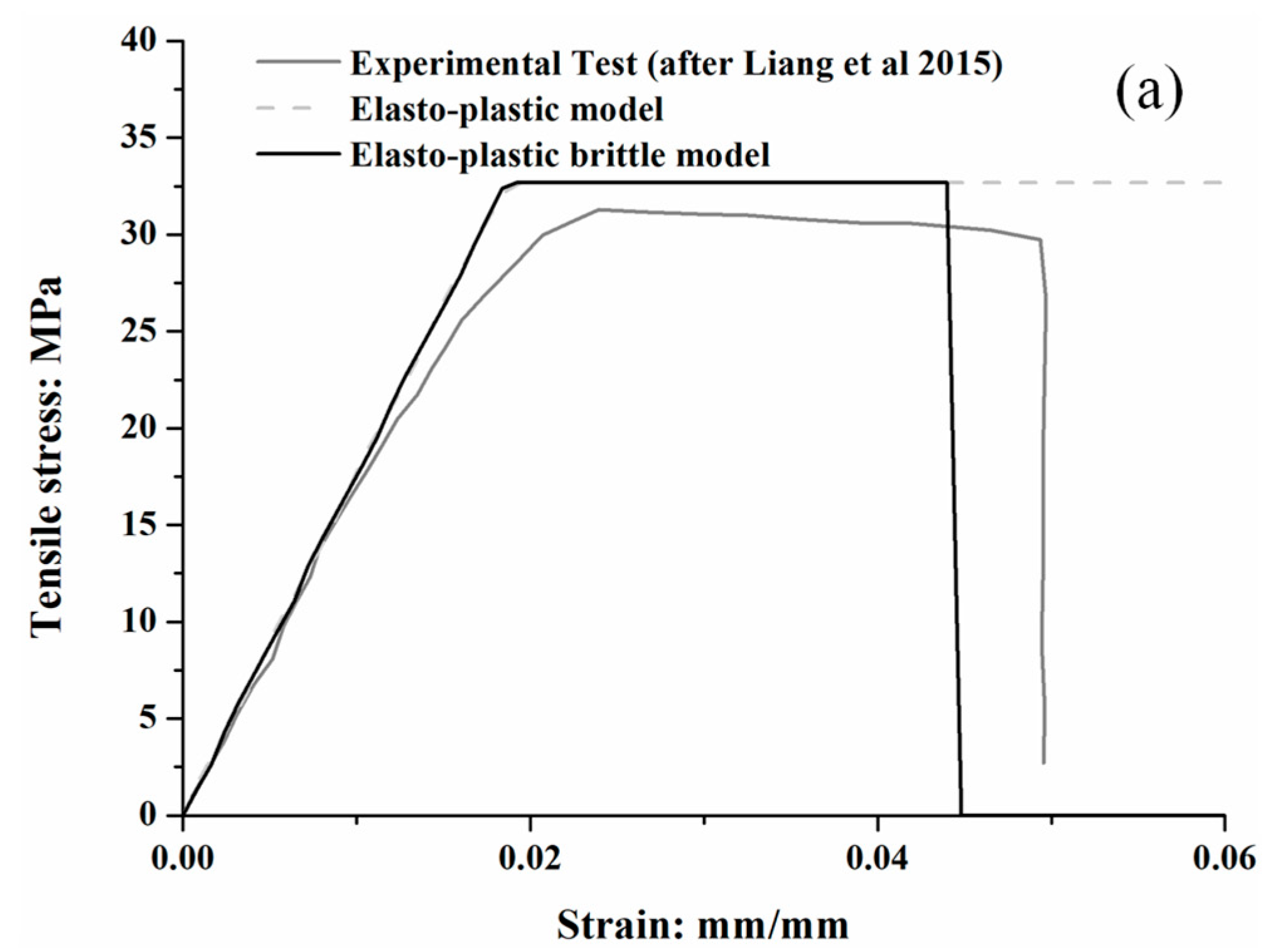
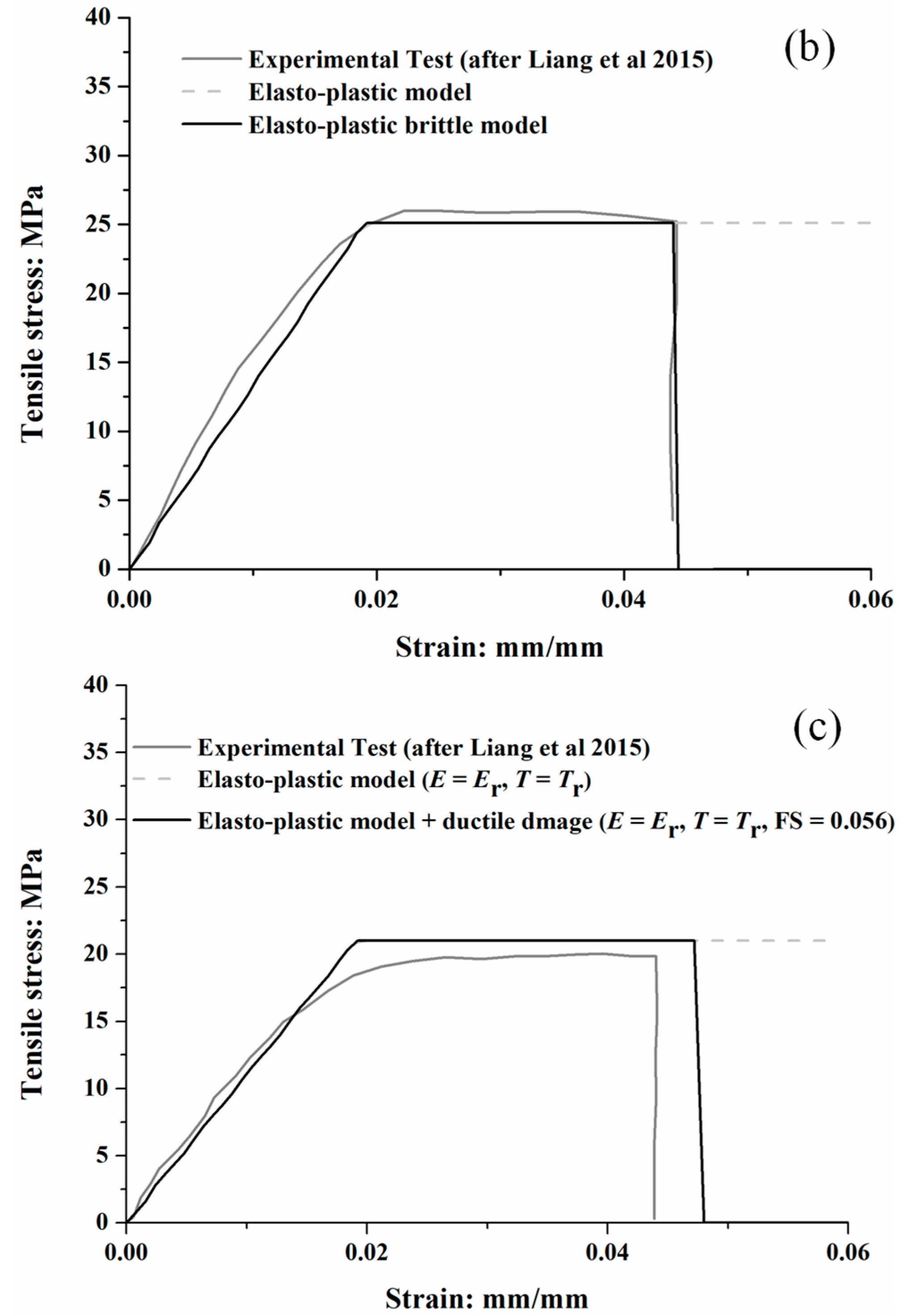
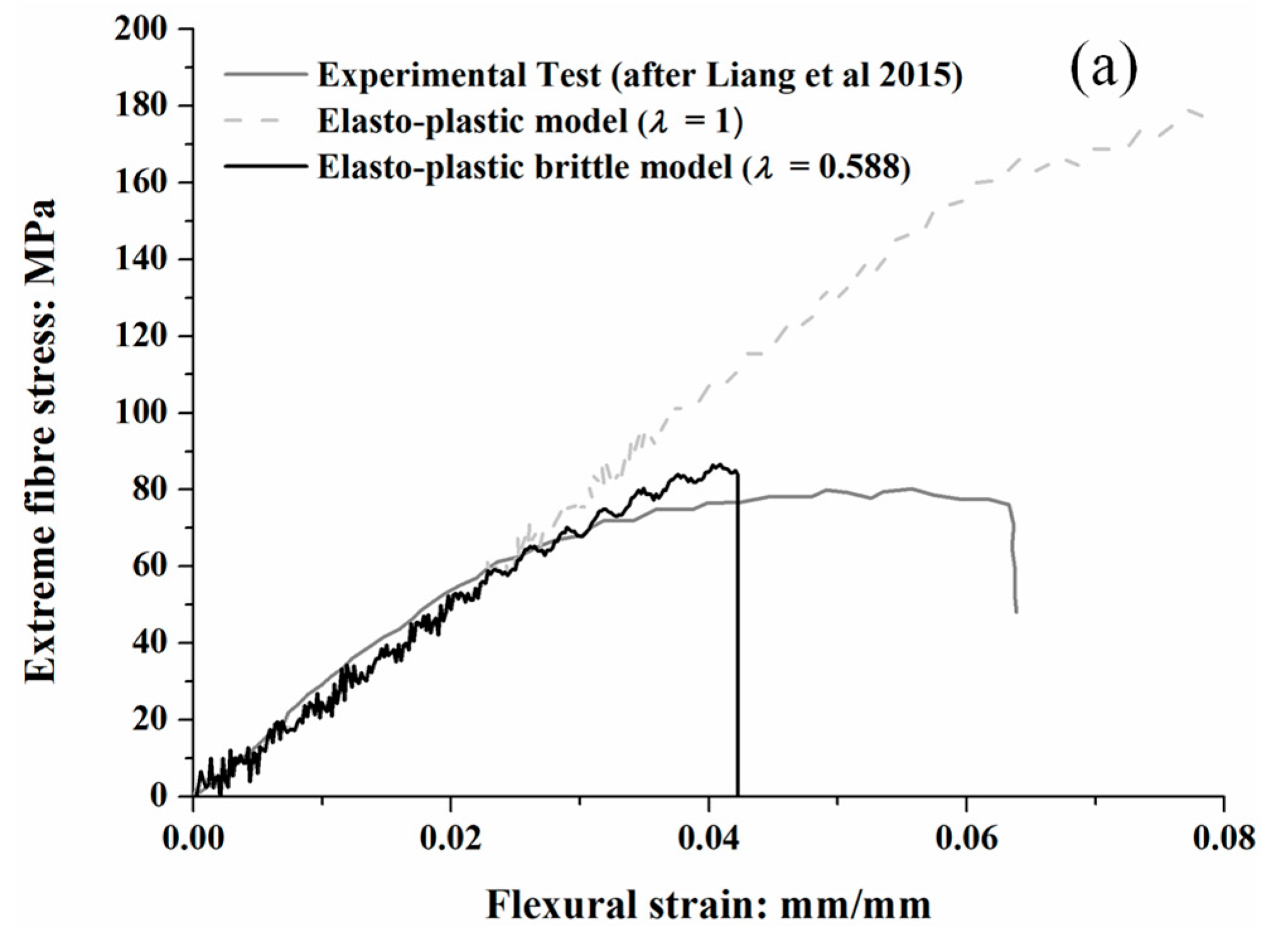
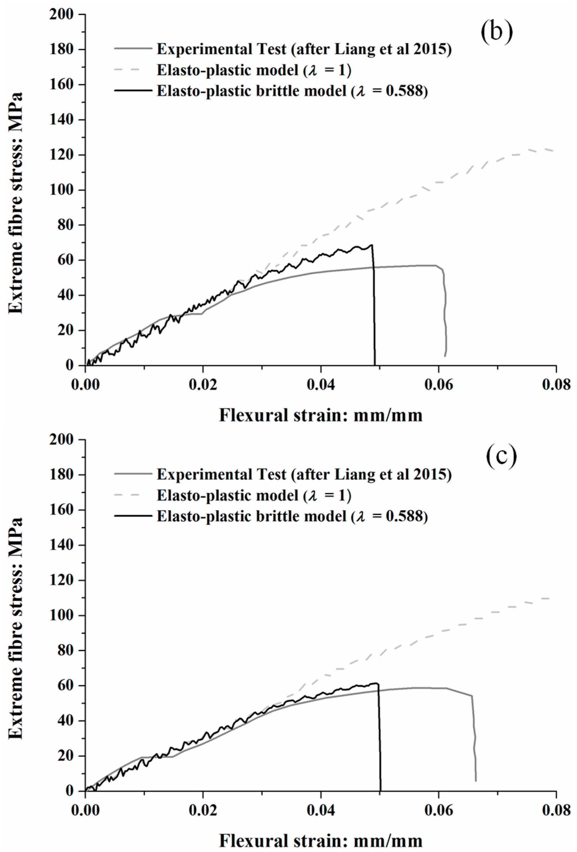
where α T , β T , α E , and β E are empirical fitting parameters and T r , E r , and d r are in MPa, GPa, and mm, respectively. Following the previous study [36], initially, for tension tests, α T , β T , α E , β E , were taken as 57.89, −0.52, 3.24, and −0.55, respectively, while, for bending tests, fitting parameters α T , β T , α E , and β E , were 164.7, −0.52, 7.27, and −0.79, respectively. The Poisson ratio was 0.35. A ductile damage model [37] was also incorporated to describe the brittle behaviour of roots. To verify associated parameters, tension and three-point bending tests were simulated on 2D beam elements, with the results shown in Figure 3 and Figure 4. The extreme fibre stress σ f plotted against flexural strain ε f curves for the bending tests in Figure 4, and they were derived from the applied load F at midspan and deflection at the point Δ , using the following:
σ f =   8 F l s π d r 3
ε f = 6 Δ d r l s 3
where l s is the distance between the two supporting points. To simulate the brittle behaviour, parameters of displacement at failure and strain rate were set to a small value of 0.0001, and stress triaxiality was set to 0.33 according to conventional tension tests. However, different values of these parameters were also checked, with no significant difference observed in root response. Fracture strain was the predominant parameter to control the strain where root breakage occurred, with a value of 0.066 selected following parametric study. Note that in experimental bending tests, the T r in Equation (1) referred to modulus of rupture MOR, defined as the extreme fibre stress at failure, when the circular root was fully plastic throughout the whole cross-section, while the input parameter of yield stress in the material model represented the point where the circular root started to yield at the extreme fibre. To capture this difference a factor λ , corresponding to the ratio of elastic section modulus to plastic section modulus (=0.588), was applied to convert MOR to the input yield stress. It can be seen from Figure 3 and Figure 4 that the behaviour of the elasto-plastic brittle model root matched well with the measured tension tests.
The considered soil had properties consistent with HST95 sand, a specific fraction of the sand extracted at Bent farm, Congleton, Cheshire, which was widely used at the University of Dundee in both physical [38] and numerical testing [39], including for root–soil interaction studies [17]. The soil was uniformly graded, with its coefficients of uniformity and curvature being 1.5 and 1, respectively, and its maximum and minimum density being 1.8 and 1.5 g/cm3, respectively. The critical state friction angle of the sand was 32°, based on direct shear tests across a range of relative densities (9%–93%) and effective confining stresses (5–200 kPa), as reported in the literature [38]. Some other index properties are summarised in Table 2.

2.3. Non-Linear Properties of p-y Connectors

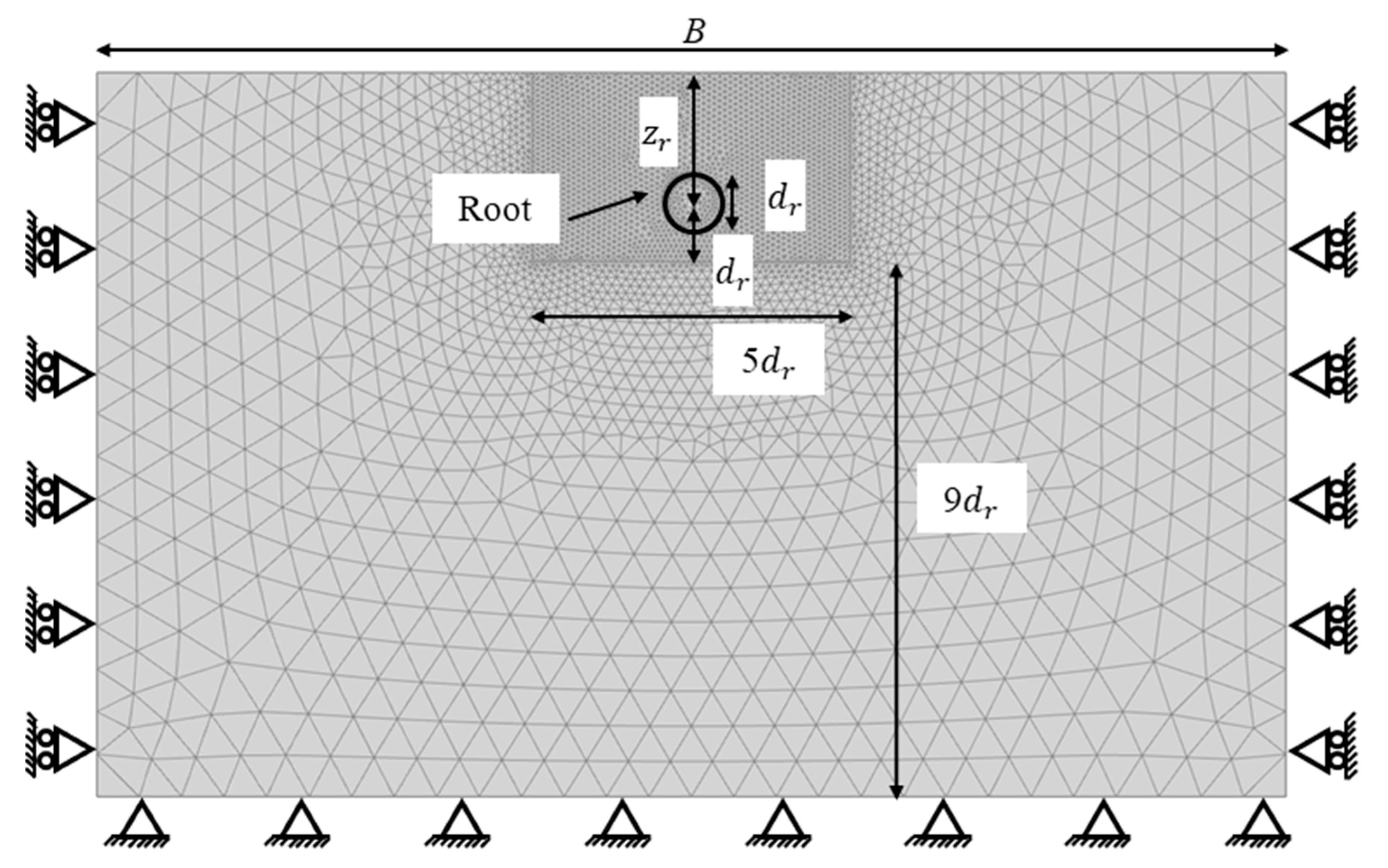
The connector properties represent the net reaction generated on the root at the location of the connector due to relative root–soil movement. Push-in of root segments was simulated with a 2D plane-strain FEM model using PLAXIS 2019 (Bentley, Delft, The Netherlands), where a wished-in-place circular root was modelled using a rigid circular plate element. As shown in Figure 5, following the previous study [40], the domain size was chosen to be large enough to avoid unwanted boundary effects on the modelling of root–soil interaction (i.e., the width B was 20 d r , and the soil beneath the root was equal to 9 d r ). The lateral boundary of the domain was restrained in the horizontal direction, the bottom was fixed in all directions, and the top boundary was free. The mesh was fine close to the root, while it became gradually coarser when approaching the boundary. Zero-thickness interface elements were used to model the root–soil interface, allowing for the opening of a gap behind the displacing root in the case of zero effective normal stress occurring during loading (no tension condition). A non-linear elasto-plastic constitutive model for the soil, called ‘hardening soil with small strain stiffness’ (‘HS small’), was employed. The key soil parameters summarised in Table 2 were previously calibrated for HST95 sand, as reported in the literature [38], with the exception of friction and dilation angle, based on an extensive series of drained direct shear and oedometer compression tests. Compared with the conventional confining stresses occurring in geotechnical structures (such as foundations), for which the parameters in Table 2 were principally derived, the effective confining stress surrounding the roots was extremely low (1.2 kPa) due to the shallow embedment depth ( z r ). This permits greater soil dilation, and to model this, the peak friction angle and dilation angle were modified according to the following [41]:
φ   φ c r i t = A I R
where A is a dimensionless factor to account for the stress conditions ( A = 5 for plane strain); ϕ c r i t is the soil friction angle at critical state (32° here); and I R is given by the following:
I R =   I D   Q   l n p R
where I D is the relative density of the sand, p is the mean effective confining stress of the soil and Q and R are the fitting parameters. At low confining stress levels, existing research [42] was proposed using Q = 7.1 + 0.75 l n p (for plane strain) and R = 1, respectively. After obtaining a revised peak friction angle ( φ ) using these expressions, following the previous study [41], the corresponding dilation angle ψ was calculated as follows:
φ   φ c r i t = 0.8 ψ
The coefficient of lateral earth pressure K 0 was determined by Jaky’s [43] formula (i.e., K 0 = 1 sin φ ). To model the process of push-in, a uniform vertical displacement was imposed on all of the nodes of the plate elements that represented the root.
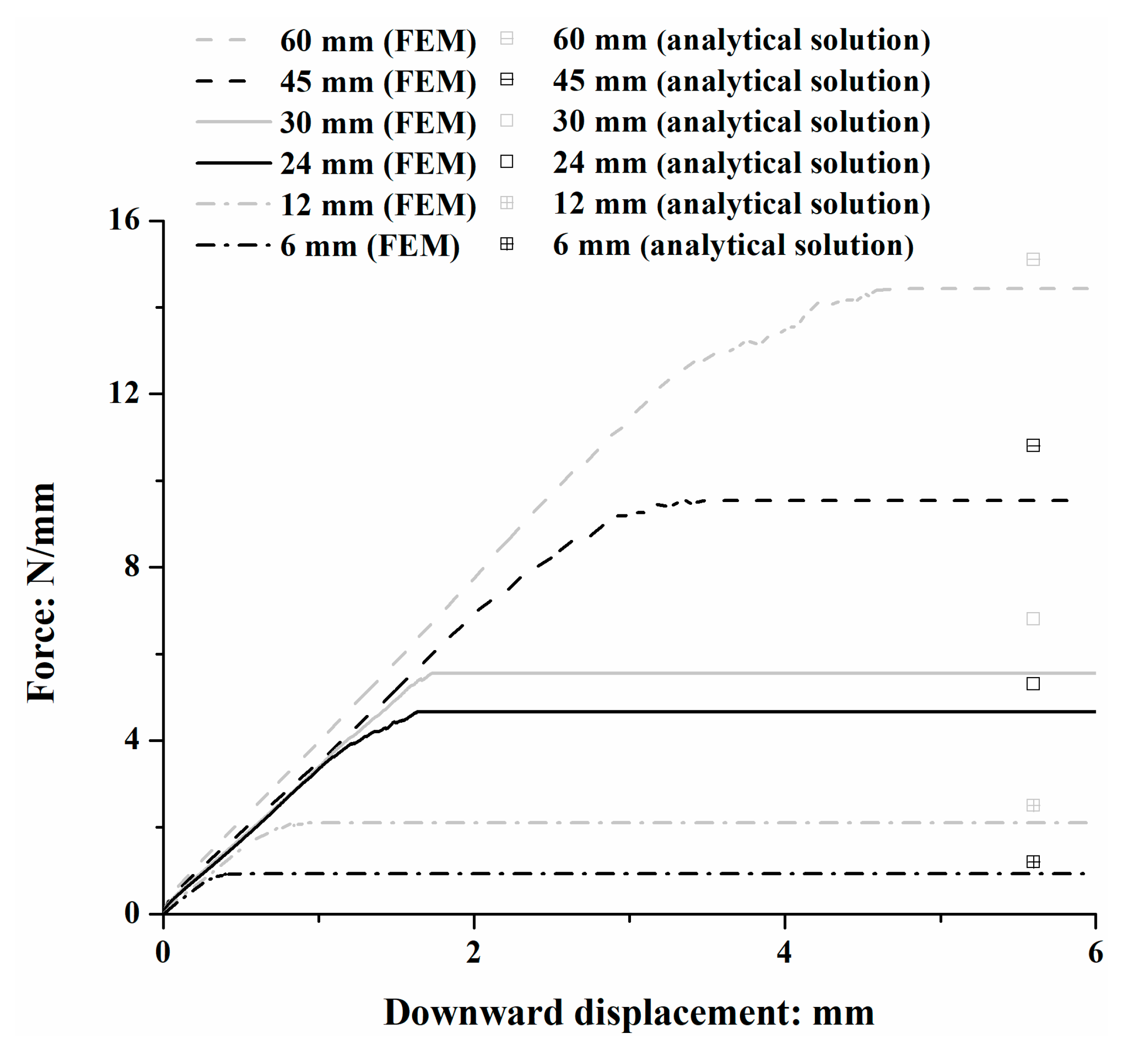
Due to severe mesh distortion at large displacement in the FEM, the force–displacement curve derived from PLAXIS was directly used to model the initial phase of the p-y connector properties in the BNWF model, followed by a plateau, as shown in Figure 6. The peak resistance was compared with an analytical solution used to estimate the maximum force on a circular pipeline moving downwards per unit length in sand [30]:
Q b =   N q γ z r d r +   N γ γ ( d r 2 ) 2
where γ is the effective unit weight of the soil, and N q and N γ are bearing capacity factors that are estimated as follows:
N q =   e π t a n φ t a n 2 ( 45 + φ 2 )
N γ = e ( 0.18 φ 2.5 )
It can be seen from Figure 6 that the bearing capacities obtained from the FEM were close to the results using the analytical solution, suggesting the reliability of the method used in this study.

2.4. Non-Linear Properties of t-z Connectors

Axial (t-z) connectors were also coupled using an elasto-plastic model. At a certain depth z , the maximum axial frictional force per unit length ( F a , m a x ) was equal to the following:
F a , m a x = ( F b +   γ z d r ) tan δ
where F b is the bearing resistance at depth z , which could be obtained in the previous section and δ is the root–soil interface friction angle (equal to 25° in this study). According to existing research [32], 90% of the axial friction is mobilised after a relative axial soil–root displacement of 0.74 mm; in this case, the axial force in the connector was assumed to linearly increase from 0 to F a , m a x when the axial displacement increased from 0 to 0.74 mm, beyond which the axial force was equal to F a , m a x constantly.

3. Results

3.1. Moment–Rotation Curves of Roots of Different Sizes

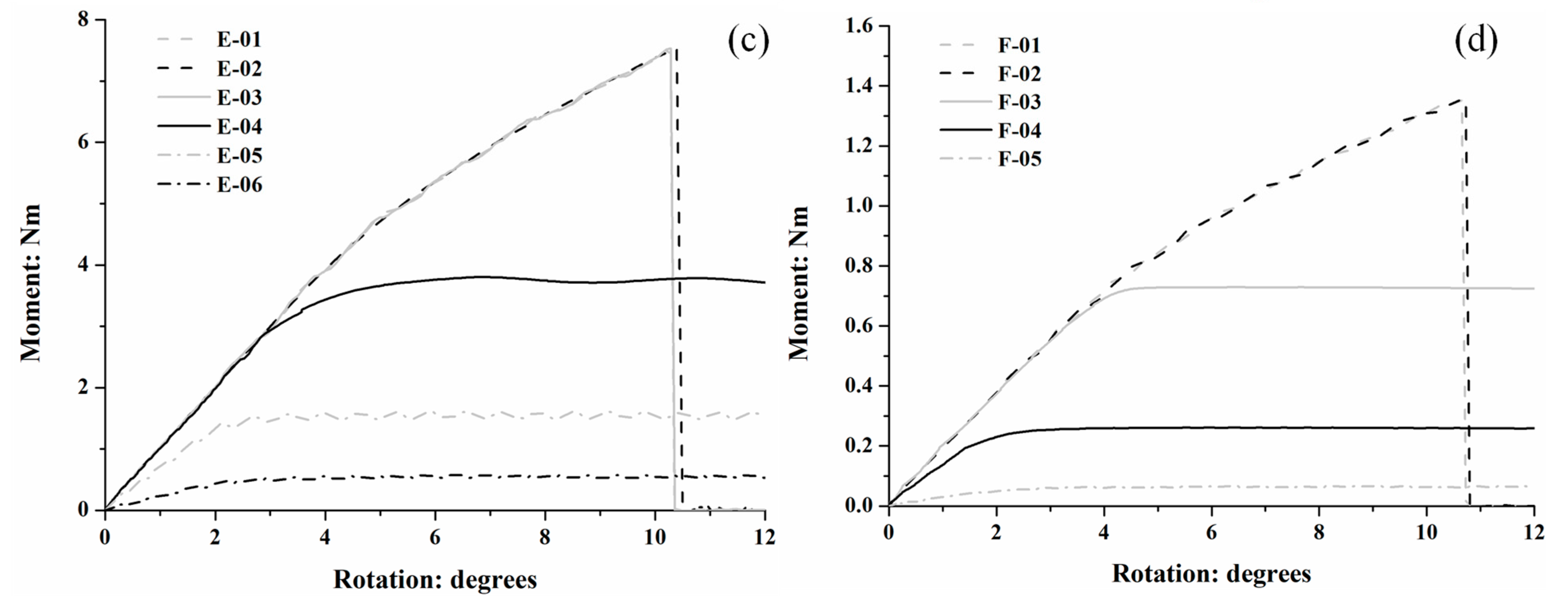
Figure 7a compares moment–rotation (M- θ ) curves, obtained from simulations A01 to A07, where all roots had the same diameter of 60 mm, but varying lengths. For relatively longer roots (i.e., >188 mm), the curves are in excellent agreement during the initial rotation, suggesting that the initial rotational stiffness of individual roots during overturning is not controlled by the root length beyond this point. However, the initial stiffness was gradually reduced as the length of the root was shortened below 188 mm. The peak moment resistance ( M p ) and the rotation angle corresponding to its onset ( θ p ) increased as the root became longer. The moment capacity rose from 90 to 400 Nm as the length increased from 120 to 314 mm, beyond which M p remained approximately constant with further increase in length (~400 Nm). Stabilisation of M p demonstrates that there was a critical length beyond which root–soil displacements are so small that there is negligible additional moment contribution from connectors beyond this point. Further discussion relating to the critical length can be found in Section 4. In cases A-04 to A-08 (corresponding to a length between 120 and 250 mm), roots first bent in the soil and then rotated about the loading point. Under large displacement, the plateau in Figure 6 was reached for all connectors, suggesting the yield of the soil around the root and resulting in the stabilisation of the moment with the increase in the rotation angle. Roots with length ≤ 188 mm were elastic during the rotation, while when length ≥ 225 mm, roots became partially plastic, with the plasticity starting from the edge of the root. In cases A-01 to A-03 (length ≥ 314 mm), a sudden drop in moment resistance was observed at a 10° rotation, where roots were snapped with plasticity reaching the centreline.
The moment–rotation curves of 30, 12, and 6 mm diameter roots with different lengths are shown in Figure 7b–d. As with the 60 mm diameter roots, the initial stiffness appeared to be independent of root length for relatively longer roots, and M p and θ p increased with increased root length up to the critical length. The initial stiffness of the moment–rotation curve was reduced for extremely short roots. Beyond the critical length, θ p was similar for all diameters, approximately equal to 10.4°. Additionally, for a given length, θ p reduced with increasing diameter as the root was stiffer.

3.2. Moment Capacities of Roots

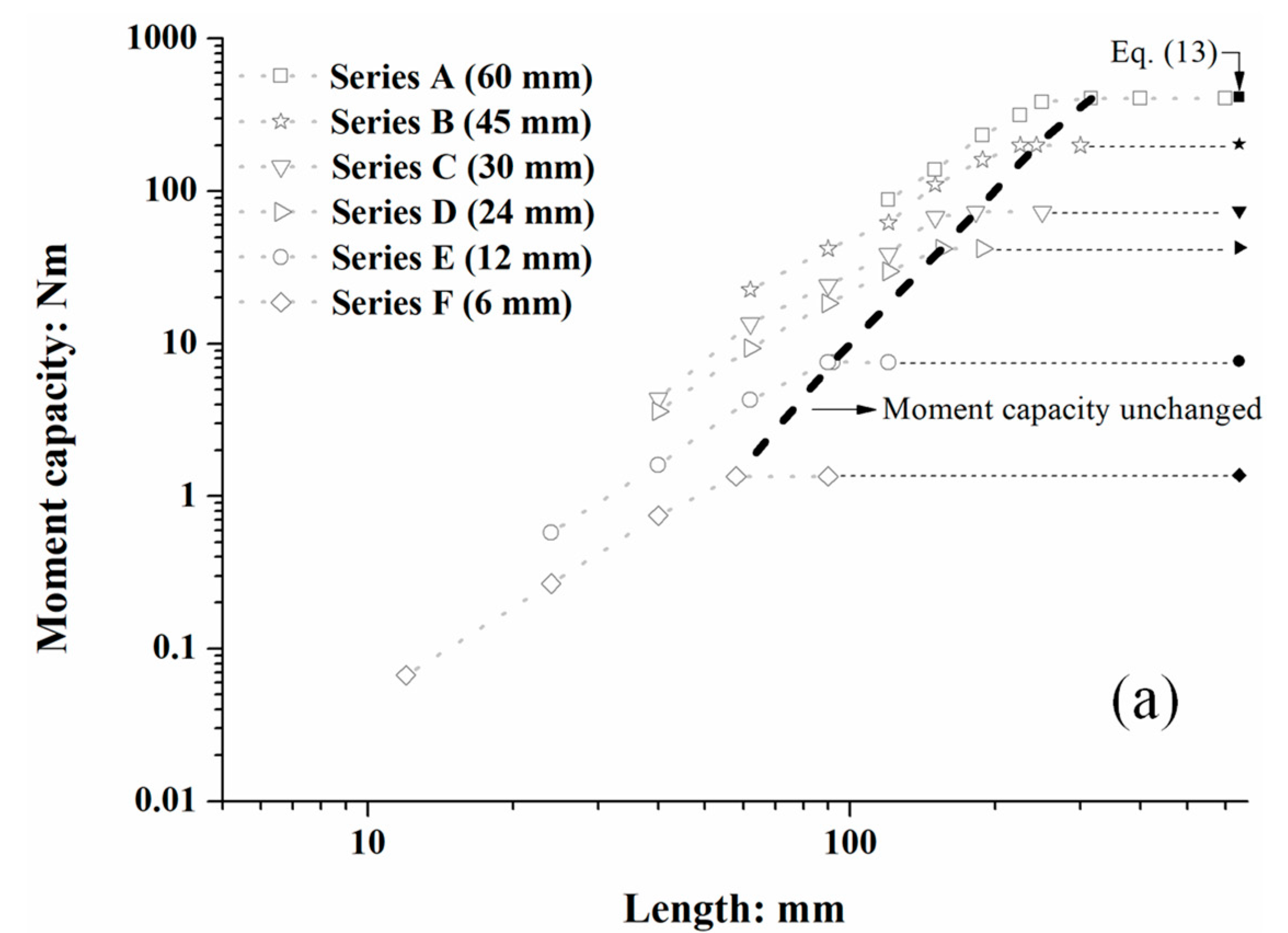
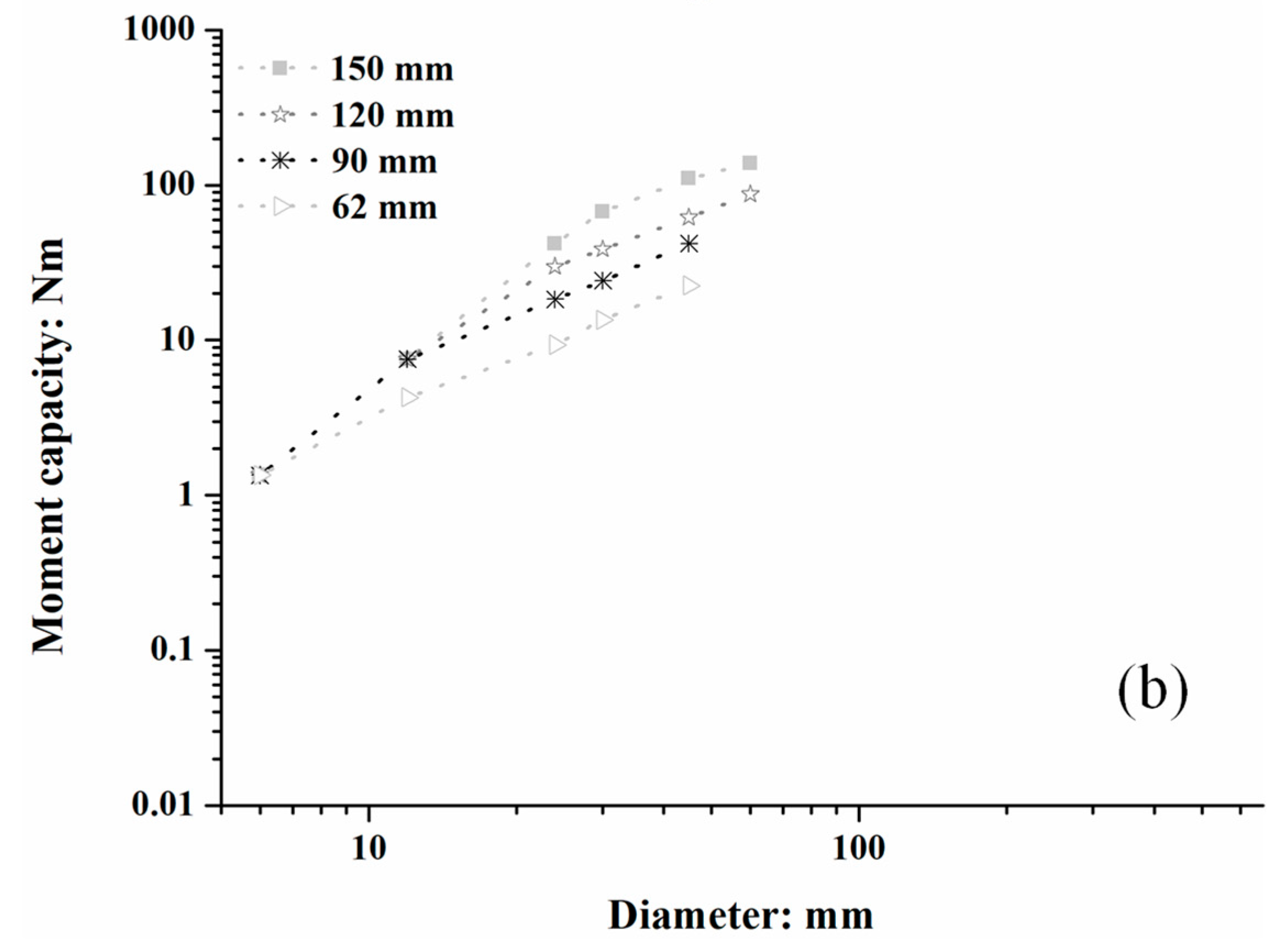
Moment capacities of all cases simulated in this study are shown in Figure 8a. It can be seen that beyond the dashed line (locus) shown, for a root of a given diameter, the moment capacity became independent of length. The dashed line, therefore, represents the critical length for leeward roots, beyond which additional root length is ineffective in contributing to overturning resistance. In Figure 8b, for a root with a given length, the moment capacity continuously increased as the root became thicker. The gradients of lines on Figure 8b are steeper than those on Figure 8a, suggesting that the moment capacity was more sensitive to diameter than length, indicating that, in terms of leeward laterals, coarse roots dominate tree-overturning behaviour.
According to Figure 7, the maximum moment capacity of a given diameter root corresponded to the length at a critical value, with the failure mechanism being the fully brittle breakage of the root occurring at the loading point, where the moment resistance was at the maximum along a single root. Therefore, the following equation should be satisfied:
T r =   M p S
where S =   π d r 3 32 is the section modulus of the root. Based on this, the moment capacity of a leeward lateral root can be estimated using the following:
M p = T r S = 164.7 d r 0.52 π d r 3 32 = 16.2 d r 2.48
As shown in Figure 8a, the moment resistances calculated using Equation (13) match well with the simulated M p for different diameters, and this could offer a simple approach to estimating the upper bound of the overturning resistance of leeward laterals in engineering practice.

3.3. Rotational Stiffness of Roots of Different Sizes

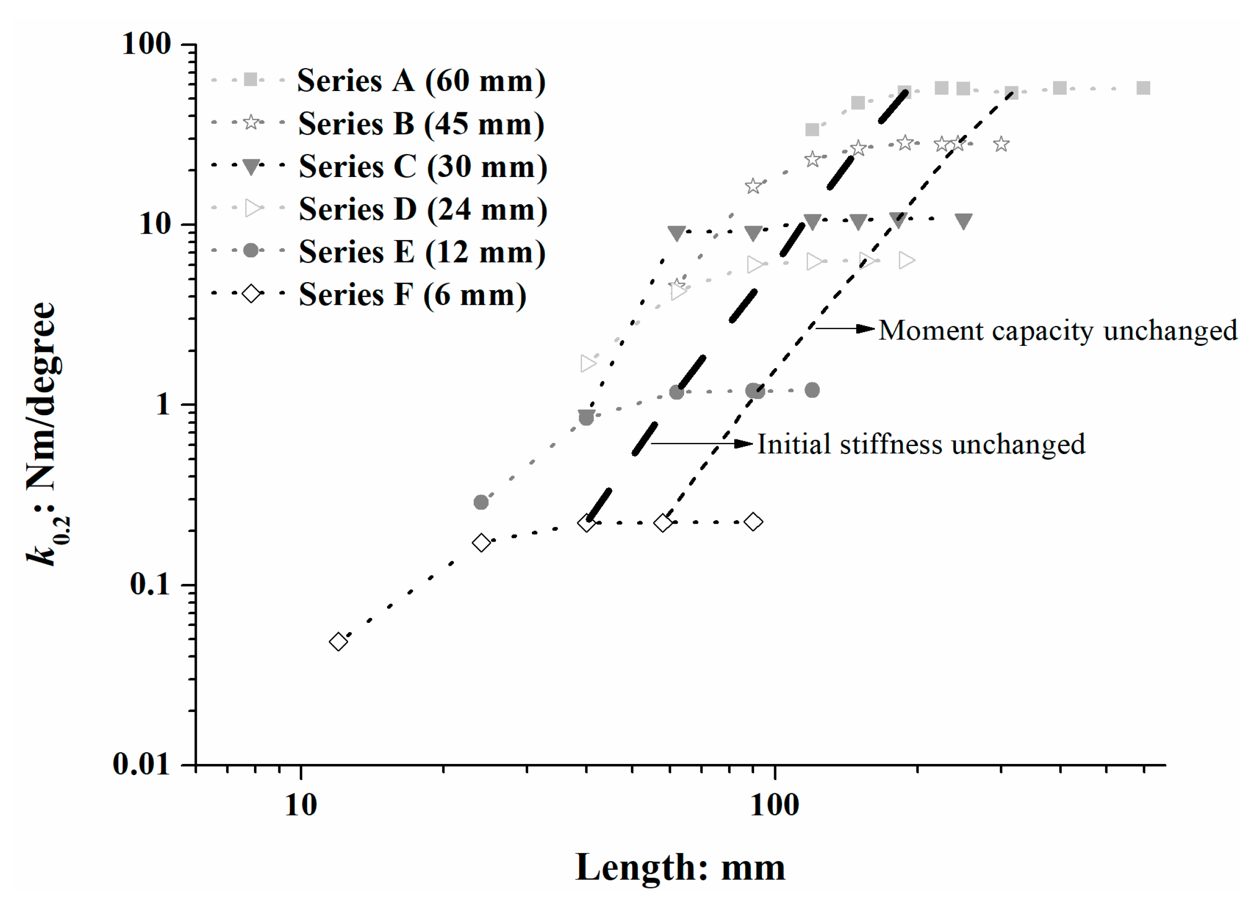
In common non-destructive field winching tests, to investigate the tree overturning resistance, the maximum rotation applied is approximately 0.2° [44]. Therefore, the rotational stiffnesses of roots calculated at this point ( k 0.2 ) of all moment–rotation curves are compared in Figure 9. It can be seen that beyond the thick dashed line, for a given root diameter k 0.2 , it was approximately independent of root length but dominantly controlled by root diameter, where, for a given length of 188 mm, k 0.2 of a 60 mm root was approximately nine times larger than that of a 24 mm root. However, for extremely short roots, k 0.2 was increased with the root length. This was also revealed in Figure 7, where the initial part of the moment–rotation curve diverged at a low slenderness ratio. The thick dashed line is on the left side of the line corresponding to the critical length, beyond which the moment capacity was unchanged (from Figure 8a), suggesting that the length to guarantee a constant initial stiffness was smaller than that to guarantee a constant moment capacity.

4. Discussion

4.1. Critical Length of Roots

The critical length in this study is defined as the maximum activated length of the root that contributes to the moment resistance when the peak moment resistance is reached. This parameter defines how much of a root contributes to overturning resistance and may, therefore, be useful in reducing the size of numerical simulations of large and complex full root system architectures. The first simulation in each series (i.e., A/B/C/D/E/F-01) was used to define the critical length ( l c ). For each of these simulations, l c was determined as the distance between the loading point and the ‘zero’ deflection point, defined as 1/100 of the maximum displacement of the root when the root had reached peak moment resistance. It is evident from Figure 7 that when the roots were longer than l c , the moment–rotation curves matched very closely. This indicates that the root–soil system reaches a state of full mobilisation along the activated length. Limiting root reinforcement has been previously observed in other root-loading combinations [45], where it was suggested that roots absorbed energy and contributed to stiffening the soil–root composite under compressive and flexural loading. For the leeward laterals in this paper, when the root is longer than the critical length, increasing root–soil deformation/tree rotation fully engages the root in bending and compression against the soil, with the resistance governed by (i) the root’s bending strength at the connection point to the trunk (rotation point) and (ii) the ultimate bearing capacity of the soil, rather than by the addition of more root material beyond the critical length.
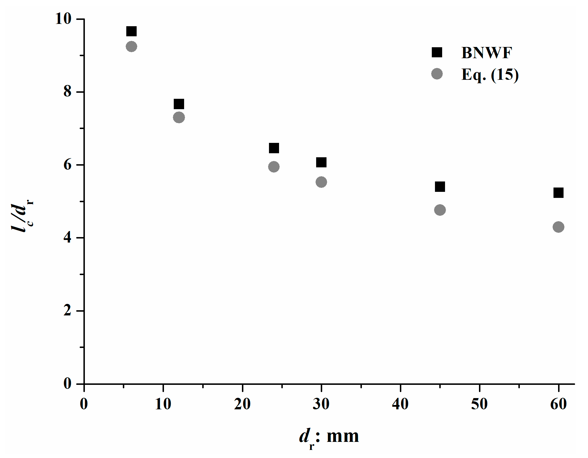
Critical length was normalised by the diameter and is shown in Figure 10. Normalised critical length reduced with the diameter, and the gradient also became smaller. Assuming that the rotation angle at peak capacity (~10.4°) was large enough to activate all connectors along the root and make the soil yield (i.e., p-y curve reaching the plateau on Figure 6), the moment capacity at the loading point should be as follows:
M l = 1 2 Q b l r 2
As shown in Figure 7, brittle breakage occurred in these cases. Based on the discussion before, the breakage was located at the loading point, with the moment being M p . Therefore, the minimum length l m i n required to achieve this is as follows:
l m i n = 2 M l Q b = 2 M p Q b
where M p is determined using Equation (13).
As the extra length would no longer contribute to the moment resistance, the l m i n here was the critical length. As shown in Figure 10, Equation (15) gives a good estimation of l c for small diameter roots, with some small discrepancies observed for coarser roots. This was because all connectors were assumed to reach the plateau; however, this was not strictly true for larger and longer roots, as both the number and capacity of the connectors were increased. In these cases, l m i n obtained from Equation (15) was smaller than l c , as some connectors had not reached the plateau.

4.2. Implications for Tree Windthrow Resistance and Tree Winching Tests

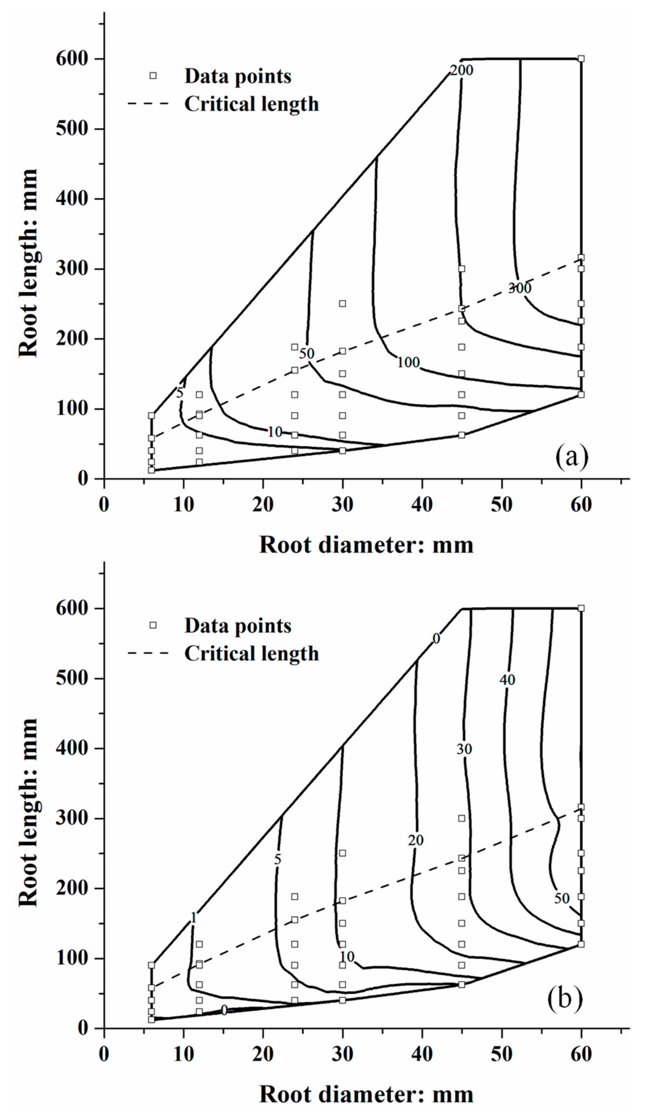
A contour plot of peak moment resistance ( M p ) of all simulations is shown in Figure 11, which indicates the relative contribution of leeward lateral roots, with diameter-dependent variation in Young’s modulus and strength taken into consideration. The critical length represents a clear boundary. Once a root exceeds this length, further increases in overturning resistance are achieved more effectively by increasing its diameter rather than its length. In contrast, short roots with a low slenderness ratio contribute to anchorage in a way that is largely independent of their diameter. Therefore, for such roots, a tree gains greater overturning resistance by prioritising the extension of root length, rather than an increase in diameter. In general, roots with a slenderness ratio larger than 10 exhibited structural (root) failure under the large rotations applied in this study, and the θ p was approximately 10.4°. This is consistent with observations of trees after the non-destructive field winching tests, where leeward laterals were intact [46], while at a large rotation, they were broken relatively close to the trunk [47]. Figure 11b presents a contour plot of rotational initial stiffness k 0.2 of all cases. Similarly to the moment capacity, k 0.2 converged to a constant value when the root became longer than the critical length. However, in contrast to moment capacity, the stiffness is largely insensitive to root length and is also below the critical length for all but the shortest roots.

4.3. Comparison with Windward Lateral Roots Across Different Root Properties

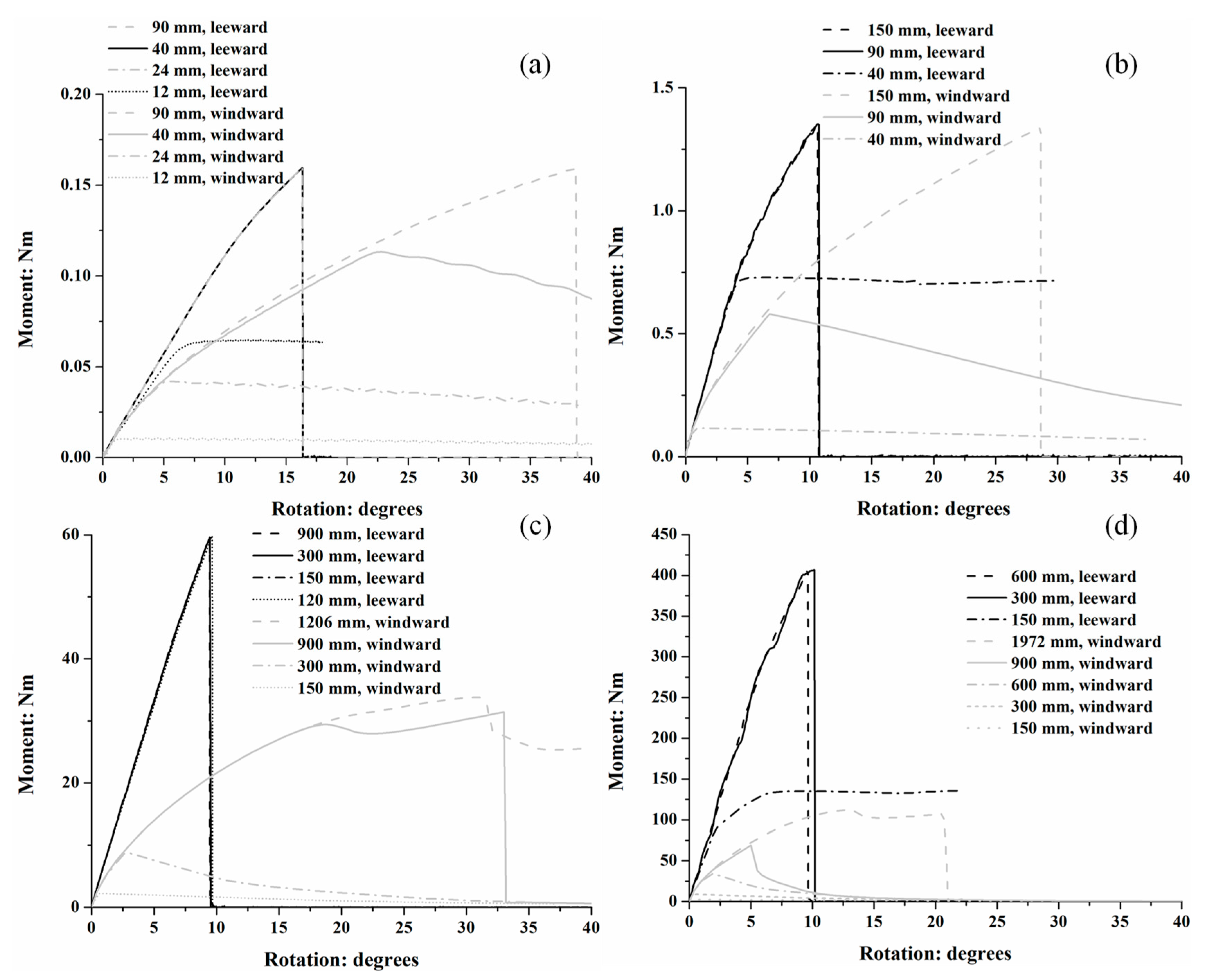
The simulations described so far were conducted using root material properties at the upper bound of typical root material for trees [36]. Further simulations were conducted on 6 and 60 mm diameter (i.e., boundary case) roots using contrasting values of E r and T r to represent P. orientalis, which is, approximately, a lower bound to typical tree root properties, where α T , β T , α E , and β E in Equations (1) and (2) were 21.936, −0.478, 0.085, and −0.316, respectively [48]. Note that other parameters were unchanged. The results were then compared with windward lateral root cases where the same roots were uplifted during the tree overturning (i.e., rotation applied in the opposite direction). The property of p-y connectors for such cases was obtained based on previous research [40]. It can be seen from Figure 12a that for 6 mm-thick roots with flexible root material, the peak moment resistance was approximately 0.16 Nm for both 90 mm-long windward and leeward roots, and this value cannot be exceeded with increased root length, as it corresponded to the breakage of roots. Leeward roots were broken ( M p = 0.16 Nm) when the length reached 24 mm; however, M p of windward roots was reduced from 0.16 to 0.04 Nm when the length was shortened to 24 mm. Generally, for the same length, the moment resistance and stiffness of leeward roots were higher than those of windward roots. Similar conclusions can be drawn in Figure 12b, where roots were all of the same diameter but in the stiffer material. The tensile strength was increased from 9.3 to 64.9 MPa, while the peak moment capacity across different lengths increased from 0.16 to 1.3 Nm approximately, indicating that M p was proportional to T r , which is consistent with Equation (7). Figure 12c,d compares 60 mm-thick windward and leeward roots in upper and lower bound materials. In addition to the moment capacity and rotational stiffness being largely increased compared with 6 mm thick roots, the overall behaviour was similar. It is also noted that for extremely long windward roots, their moment capacities were still much lower than shorter leeward roots, suggesting that leeward laterals contribute more to the moment resistance during tree overturning. This was consistent with previous field winching tests, where all of the leeward laterals were damaged, while only 12% of windward laterals were damaged during the overturing process [49].
This study provides a preliminary investigation into understanding the root–soil interaction behaviour of leeward lateral (structural) roots, considering the effect of root diameter, root length, and root material properties. However, it should be acknowledged that the simulations here do not consider the effects of tortuosity or tapering, which would be case-specific. These parameters could be considered straightforward within the BNWF model if required through modifications to the beam geometry and varying parameters, element-wise, along the simulated root. Different ground conditions could similarly be accounted for through modification of the p-y connector properties.

4.4. Consideration of Natural Variability and Model Applicability

Application of the BNWF approach to natural environments must consider several biological and geotechnical variabilities. The model can be adapted to different tree species by adjusting the root material properties ( E r , T r ) and geometry ( d r , l r ), which are known to vary significantly among species. For instance, hardwoods typically exhibit higher tensile strength than conifers, which would enhance moment capacity. The current model structure allows for such adjustments through modified beam and connector properties. In addition, root mechanical properties and dimensions evolve with tree age. Older roots often exhibit larger diameters and sometimes reduced flexibility. These changes can be incorporated into the model by updating d r , E r , and T r based on allometric or species-specific ageing models, allowing simulations to reflect maturation effects on anchorage. Although the current model considers straight first-order roots, branching can be incorporated by adding secondary beam elements and calibrating local p-y and t-z responses for these (e.g., [29] for branching sinker roots). Branching increases soil–root contact and may redistribute stresses, potentially enhancing rotational stiffness and moment capacity. The BNWF model can accommodate depth- or spatially varying soil properties by assigning different p-y and t-z curves along the root length. This allows simulation of heterogeneous site-specific profiles such as weak topsoil over stiff subsoil, which may influence the critical root length and failure mode. While the current study focuses on roots that are well-spaced from their neighbours, the BNWF framework can be extended to multiple roots attached to the trunk and multiple root systems within a shared soil domain via root–root coupling springs if required, enabling analysis of group effects and system-level stability. Future studies incorporating these factors will further enhance the model’s predictive accuracy and practical relevance.
Overall, this study underscores that root-bending resistance is a fundamental yet under-represented mechanism in tree anchorage modelling. Integrating the perspective of roots absorbing flexural energy [45] with empirical evidence highlights the dominance of large roots in stabilising soil [50]. These insights emphasise the need to incorporate root bending and root–soil interaction mechanics for large roots explicitly within future anchorage models.

5. Conclusions

This study has systematically investigated the rotational behaviour of leeward lateral roots during tree overturning through a numerical modelling approach based on the beam-on-nonlinear-Winkler-foundation (BNWF) concept. The simulations, which varied root diameter, length, and material properties, revealed the existence of a critical root length, beyond which further increases in length do not contribute to higher moment resistance. This critical length increases in absolute terms with larger diameters. Moment capacity was found to be significantly more sensitive to changes in root diameter than to changes in length, underscoring the dominant role of thicker roots in providing overturning resistance. For very short roots below the critical length, the contribution to anchorage becomes more dependent on length than on diameter. These findings provide practical guidance for forest management, suggesting that promoting the growth of thicker lateral roots, through species selection, silvicultural practices, or site-specific interventions, can be more effective for enhancing stand stability than merely encouraging longer roots.
The initial rotational stiffness, a parameter highly relevant to non-destructive field winching tests, was primarily controlled by root diameter and remained largely independent of length for the majority of cases, except for extremely short roots. A comparative analysis between leeward and windward roots under a given trunk rotation unequivocally demonstrated the superior contribution of leeward roots to overturning resistance, with these roots exhibiting significantly higher moment capacity and stiffness than windward roots of the same dimensions. This finding aligns with field observations from winching tests and windthrown trees and confirms the pivotal role of leeward lateral roots in tree anchorage. Therefore, forest management practices aimed at reducing windthrow risk should prioritise the protection and development of leeward lateral root systems, especially in high-wind or landslide-prone areas.
The outcomes of this research provide valuable quantitative insights for predicting the overturning resistance of trees. The BNWF model employed in this study proved to be a computationally efficient and robust tool for simulating large deformation root–soil interaction, successfully capturing the transition from elastic soil reaction to plastic yielding and ultimately root breakage, suitable for integration into larger-scale models of complete root systems, facilitating more accurate assessment of tree stability and windthrow risk. Furthermore, especially for South China, these findings offer practical guidance for forest management and the design of nature-based mitigation strategies against shallow landslides and debris flows, emphasising the importance of fostering root systems with robust lateral roots. Future work should focus on incorporating more biological realism into the model, such as root tortuosity, tapering, and branching, to enhance its predictive accuracy across diverse tree species and soil conditions, thereby supporting more informed and species-specific forest management decisions.

Author Contributions

J.K. and X.Z. conceived of and designed the study. X.Z. and T.Z. performed the research. J.K., Z.Z., T.L., S.K., M.C. and A.L. discussed, shared ideas, and critically revised the manuscript based on the first draft by X.Z. All authors improved the manuscript significantly with their critical comments. All authors have read and agreed to the published version of the manuscript.

Funding

The first author would like to acknowledge the financial support of the South China Field Scientific Observation and Research Station for Climate-Driven Landslide Risk, Ministry of Natural Resources, the Natural Science Foundation of Jiangsu Province (Grant No. BK20230895), the Fundamental Research Funds for the Central Universities (Grant No. NS2025021), and the National Natural Science Foundation of China (Grants No. 52408541 and 52378373). The last author would like to acknowledge the funding provided by the Hong Kong Research Grant Council (16202422, 16207521) and the State Key Laboratory of Climate Resilience for Coastal Cities (ITC-SKLCRCC26EG01).

Data Availability Statement

The original contributions presented in this study are included in the article. Further inquiries can be directed to the corresponding authors.

Acknowledgments

The South China Field Scientific Observation and Research Station for Climate-Driven Landslide Risk, Ministry of Natural Resources and the Fundamental Research Funds for the Central Universities are acknowledged for the financial support.

Conflicts of Interest

The authors declare no conflicts of interest.

References

  1. Mickovski, S.B.; Stokes, A.; van Beek, R.; Ghestem, M.; Fourcaud, T. Simulation of Direct Shear Tests on Rooted and Non-Rooted Soil Using Finite Element Analysis. Ecol. Eng. 2011, 37, 1523–1532. [Google Scholar] [CrossRef]
  2. Meijer, G.; Bengough, G.; Knappett, J.; Loades, K.; Nicoll, B. Measuring the Strength of Root-Reinforced Soil on Steep Natural Slopes Using the Corkscrew Extraction Method. Forests 2019, 10, 1135. [Google Scholar] [CrossRef]
  3. Smethurst, J.A.; Clarke, D.; Powrie, W. Factors Controlling the Seasonal Variation in Soil Water Content and Pore Water Pressures within a Lightly Vegetated Clay Slope. Géotechnique 2012, 62, 429–446. [Google Scholar] [CrossRef]
  4. Grimaldi, S.; Orellana, F.; Daly, E. Modelling the Effects of Soil Type and Root Distribution on Shallow Groundwater Resources. Hydrol. Process. 2015, 29, 4457–4469. [Google Scholar] [CrossRef]
  5. McCarthy, J.K.; Hood, I.A.; Brockerhoff, E.G.; Carlson, C.A.; Pawson, S.M.; Forward, M.; Walbert, K.; Gardner, J.F. Predicting Sapstain and Degrade in Fallen Trees Following Storm Damage in a Pinus Radiata Forest. For. Ecol. Manag. 2010, 260, 1456–1466. [Google Scholar] [CrossRef]
  6. Romagnoli, F.; Cadei, A.; Costa, M.; Marangon, D.; Pellegrini, G.; Nardi, D.; Masiero, M.; Secco, L.; Grigolato, S.; Lingua, E.; et al. Windstorm Impacts on European Forest-Related Systems: An Interdisciplinary Perspective. For. Ecol. Manag. 2023, 541, 121048. [Google Scholar] [CrossRef]
  7. Triviño, M.; Potterf, M.; Tijerín, J.; Ruiz-Benito, P.; Burgas, D.; Eyvindson, K.; Blattert, C.; Mönkkönen, M.; Duflot, R. Enhancing Resilience of Boreal Forests Through Management Under Global Change: A Review. Curr. Landsc. Ecol. Rep. 2023, 8, 103–118. [Google Scholar] [CrossRef]
  8. Jakob, M.; Lambert, S. Climate Change Effects on Landslides along the Southwest Coast of British Columbia. Geomorphology 2009, 107, 275–284. [Google Scholar] [CrossRef]
  9. Brang, P.; Schönenberger, W.; Ott, E.; Gardner, B. Forests as Protection from Natural Hazards. In The Forests Handbook, Volume 2: Applying Forest Science for Sustainable Management; Evans, J., Ed.; John Wiley & Sons: Hoboken, NJ, USA, 2001; pp. 53–81. ISBN 9780632048236. [Google Scholar]
  10. Zhang, Q.; Zhang, W.; Chen, Y.D.; Jiang, T. Flood, Drought and Typhoon Disasters During the Last Half-Century in the Guangdong Province, China. Nat. Hazards 2011, 57, 267–278. [Google Scholar] [CrossRef]
  11. Coutts, M.P. Root Architecture and Tree Stability. Plant Soil 1983, 71, 171–188. [Google Scholar] [CrossRef]
  12. Nicoll, B.C.; Gardiner, B.A.; Peace, A.J. Improvements in Anchorage Provided by the Acclimation of Forest Trees to Wind Stress. Forestry 2008, 81, 389–398. [Google Scholar] [CrossRef]
  13. Marchi, L.; Grigolato, S.; Mologni, O.; Scotta, R.; Cavalli, R.; Montecchio, L. State of the Art on the Use of Trees as Supports and Anchors in Forest Operations. Forests 2018, 9, 467. [Google Scholar] [CrossRef]
  14. Danjon, F.; Barker, D.H.; Drexhage, M.; Stokes, A. Using Three-Dimensional Plant Root Architecture in Models of Shallow-Slope Stability. Ann. Bot. 2008, 101, 1281–1293. [Google Scholar] [CrossRef]
  15. Smith, A.; Astrup, R.; Raumonen, P.; Liski, J.; Krooks, A.; Kaasalainen, S.; Åkerblom, M.; Kaasalainen, M. Tree Root System Characterization and Volume Estimation by Terrestrial Laser Scanning and Quantitative Structure Modeling. Forests 2014, 5, 3274–3294. [Google Scholar] [CrossRef]
  16. Harnas, F.R.; Rahardjo, H.; Leong, E.C.; Tan, P.Y.; Ow, L.F. Stability of Containerized Urban Street Trees. Landsc. Ecol. Eng. 2016, 12, 13–24. [Google Scholar] [CrossRef]
  17. Zhang, X.; Knappett, J.A.; Leung, A.K.; Ciantia, M.O.; Liang, T.; Danjon, F. Small-Scale Modelling of Root-Soil Interaction of Trees Under Lateral Loads. Plant Soil 2020, 456, 289–305. [Google Scholar] [CrossRef]
  18. Zhang, X.; Knappett, J.A.; Leung, A.K.; Liang, T. Physical Modelling of Soil-Structure Interaction of Tree Root Systems under Lateral Loads. In Proceedings of the 9th International Conference on Physical Modelling in Geoetchnics, London, UK, 16–19 July 2018; pp. 481–486. [Google Scholar]
  19. Zhang, X.; Knappett, J.A.; Leung, A.K.; Ciantia, M.O.; Liang, T.; Nicoll, B.C. Centrifuge Modelling of Root-Soil Interaction of Laterally Loaded Trees Under Different Loading Conditions. Géotechnique 2023, 73, 766–780. [Google Scholar] [CrossRef]
  20. Dupuy, L.X.; Fourcaud, T.; Lac, P.; Stokes, A. A Generic 3D Finite Element Model of Tree Anchorage Integrating Soil Mechanics and Real Root System Architecture. Am. J. Bot. 2007, 94, 1506–1514. [Google Scholar] [CrossRef]
  21. Yang, M.; Défossez, P.; Danjon, F.; Fourcaud, T. Analyzing Key Factors of Roots and Soil Contributing to Tree Anchorage of Pinus Species. Trees Struct. Funct. 2018, 32, 703–712. [Google Scholar] [CrossRef]
  22. Huang, Q.; Wang, Y.; Leung, A.K.; Zhu, J. Large Deformation Simulation of Uprooting of Trees with Complex Root System Architectures Using Material Point Method with Embedded Truss Elements. Plant Soil 2024, 511, 1355–1384. [Google Scholar] [CrossRef]
  23. Chiatante, D.; Scippa, S.G.; Di Iorio, A.; Sarnataro, M. The Influence of Steep Slopes on Root System Development. J. Plant Growth Regul. 2002, 21, 247–260. [Google Scholar] [CrossRef]
  24. Giadrossich, F.; Schwarz, M.; Cohen, D.; Cislaghi, A.; Vergani, C.; Hubble, T.; Phillips, C.; Stokes, A. Methods to Measure the Mechanical Behaviour of Tree Roots: A Review. Ecol. Eng. 2017, 109, 256–271. [Google Scholar] [CrossRef]
  25. Masi, E.B.; Segoni, S.; Tofani, V. Root Reinforcement in Slope Stability Models: A Review. Geosciences 2021, 11, 212. [Google Scholar] [CrossRef]
  26. Mickovski, S.B.; van Beek, L.P.H. Root Morphology and Effects on Soil Reinforcement and Slope Stability of Young Vetiver (Vetiveria zizanioides) Plants Grown in Semi-Arid Climate. Plant Soil 2009, 324, 43–56. [Google Scholar] [CrossRef]
  27. Karimzadeh, A.A.; Leung, A.K.; Gao, Z. Shear Strength Anisotropy of Rooted Soils. Geotechnique 2022, 74, 1033–1046. [Google Scholar] [CrossRef]
  28. Schwarz, M.; Cohen, D.; Or, D. Root-Soil Mechanical Interactions during Pullout and Failure of Root Bundles. J. Geophys. Res. Earth Surf. 2010, 115, 1–19. [Google Scholar] [CrossRef]
  29. Zhang, X.; Ciantia, M.O.; Knappett, J.A.; Leung, A.K.; Liang, T. Particle Size Effects on the Axial Pull-out and Push-in Behaviour of Roots. Acta Geotech. 2024, 19, 1461–1476. [Google Scholar] [CrossRef]
  30. Wu, J.; Kouretzis, G.; Suwal, L. Bearing Capacity Mechanisms for Pipes Buried in Sand. Can. Geotech. J. 2021, 58, 834–847. [Google Scholar] [CrossRef]
  31. Reese, L.C.; Van Impe, W.F. Single Piles and Pile Groups under Lateral Loading, 2nd ed.; CRC: Leiden, The Netherlands, 2011. [Google Scholar]
  32. Meijer, G.J.; Wood, D.M.; Knappett, J.A.; Bengough, G.A. Analysis of Coupled Axial and Lateral Deformation of Roots in Soil. Int. J. Numer. Anal. Methods Geomech. 2019, 43, 684–707. [Google Scholar] [CrossRef]
  33. Danjon, F.; Caplan, J.S.; Fortin, M.; Meredieu, C. Descendant Root Volume Varies as a Function of Root Type: Estimation of Root Biomass Lost During Uprooting in Pinus pinaster. Front. Plant Sci. 2013, 4, 402. [Google Scholar] [CrossRef]
  34. Schwarz, M.; Lehmann, P.; Or, D. Quantifying Lateral Root Reinforcement in Steep Slopes—From a Bundle of Roots to Tree Stands. Earth Surf. Process. Landf. 2010, 35, 354–367. [Google Scholar] [CrossRef]
  35. Mao, Z.; Saint-André, L.; Genet, M.; Mine, F.X.; Jourdan, C.; Rey, H.; Courbaud, B.; Stokes, A. Engineering Ecological Protection Against Landslides in Diverse Mountain Forests: Choosing Cohesion Models. Ecol. Eng. 2012, 45, 55–69. [Google Scholar] [CrossRef]
  36. Liang, T.; Knappett, J.A.; Duckett, N. Modelling the Seismic Performance of Rooted Slopes from Individual Root–Soil Interaction to Global Slope Behaviour. Géotechnique 2015, 65, 995–1009. [Google Scholar] [CrossRef]
  37. Hillerborg, A.; Modeer, M.; Petersson, P.E. Analysis of Crack Formation and Crack Growth in Concrete by Means of Fracture Mechanics and Finite Elements; American Concrete Institute (ACI): Farmington Hills, MI, USA, 2008; Volume SP-249, pp. 225–237. [Google Scholar]
  38. Al-Defae, A.H.; Caucis, K.; Knappett, J.A. Aftershocks and the Whole-Life Seismic Performance of Granular Slopes. Géotechnique 2013, 63, 1230–1244. [Google Scholar] [CrossRef]
  39. Cerfontaine, B.; Knappett, J.; Brown, M.J.; Davidson, C.; Sharif, Y. Optimised Design of Screw Anchors in Tension in Sand for Renewable Energy Applications. Ocean Eng. 2020, 217, 108010. [Google Scholar] [CrossRef]
  40. Zhang, X.; Knappett, J.A.; Ciantia, M.O.; Leung, A.K.; Wang, H.; Liang, T. Root Size Effects on Transverse Root-Soil Interactions. Comput. Geotech. 2024, 165, 105860. [Google Scholar] [CrossRef]
  41. Bolton, M.D. The Strength and Dilatancy of Sands. Géotechnique 1986, 36, 65–78. [Google Scholar] [CrossRef]
  42. Chakraborty, T.; Salgado, R. Dilatancy and Shear Strength of Sand at Low Confining Pressures. J. Geotech. Geoenviron. Eng. 2010, 136, 527–532. [Google Scholar] [CrossRef]
  43. Jaky, J. The Coefficient of Earth Pressure at Rest. J. Soc. Hung. Archit. Eng. 1944, 78, 355–358. [Google Scholar]
  44. Galli, A.; Sala, C.; Castellanza, R.; Marsiglia, A.; Ciantia, M.O. Lesson Learnt from Static Pulling Tests on Trees: An Experimental Study on Toppling Behaviour of Complex Foundations. Acta Geotech. 2024, 19, 1477–1494. [Google Scholar] [CrossRef]
  45. Schwarz, M.; Rist, A.; Cohen, D.; Giadrossich, F.; Egorov, P.; Büttner, D.; Stolz, M.; Thormann, J.J. Root Reinforcement of Soils Under Compression. J. Geophys. Res. Earth Surf. 2015, 120, 2103–2120. [Google Scholar] [CrossRef]
  46. Coutts, M.P. Components of Tree Stability in Sitka Spruce on Peaty Gley Soil. Forestry 1986, 59, 173–197. [Google Scholar] [CrossRef]
  47. Crook, M.J.; Ennos, A.R. The Mechanics of Root Lodging in Winter Wheat, Triticum aestivum L. J. Exp. Bot. 1993, 44, 1219–1224. [Google Scholar] [CrossRef]
  48. Ji, J.; Kokutse, N.; Genet, M.; Fourcaud, T.; Zhang, Z. Effect of Spatial Variation of Tree Root Characteristics on Slope Stability. A Case Study on Black Locust (Robinia pseudoacacia) and Arborvitae (Platycladus orientalis) Stands on the Loess Plateau, China. Catena 2012, 92, 139–154. [Google Scholar] [CrossRef]
  49. Crook, M.J.; Ennos, A.R. The Anchorage Mechanics of Deep Rooted Larch, Larix europea × L. japonica. J. Exp. Bot. 1996, 47, 1509–1517. [Google Scholar] [CrossRef]
  50. Giadrossich, F.; Cohen, D.; Schwarz, M.; Ganga, A.; Marrosu, R.; Pirastru, M.; Capra, G.F. Large Roots Dominate the Contribution of Trees to Slope Stability. Earth Surf. Process. Landf. 2019, 44, 1602–1609. [Google Scholar] [CrossRef]
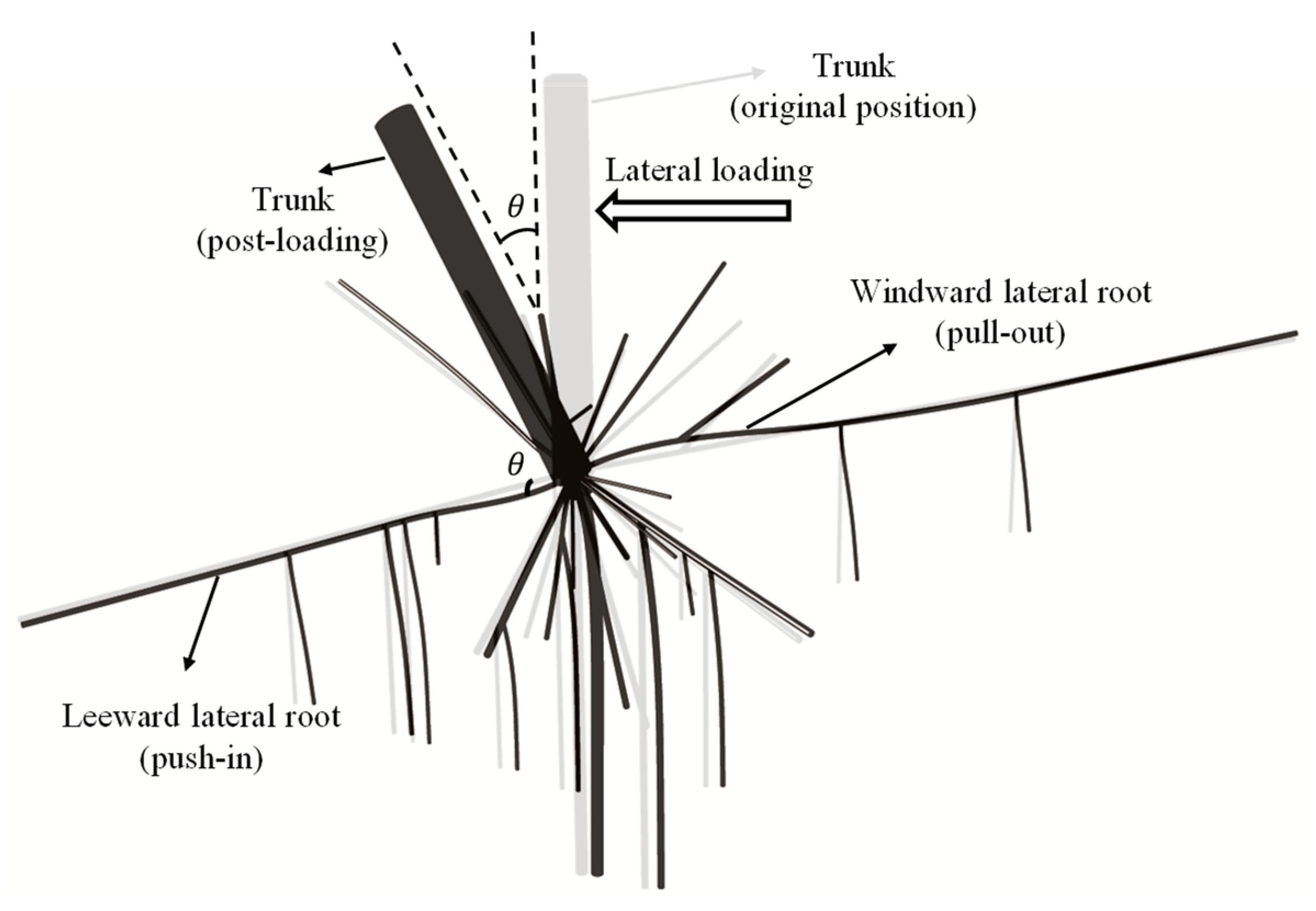
Figure 1. Simplified tree root system under lateral loading.
Forests 16 01692 g001
Figure 2. Schematic diagram (not to scale) of leeward lateral root–soil system undergoing rotational loading (BNWF model).
Forests 16 01692 g002
Figure 3. Validation of tensile tests using roots of diameter: (a) 3 mm; (b) 5 mm; and (c) 7 mm [36].
Forests 16 01692 g003aForests 16 01692 g003b
Figure 4. Validation of bending tests using roots of diameter: (a) 4 mm; (b) 6 mm; and (c) 7 mm [36].
Forests 16 01692 g004aForests 16 01692 g004b
Figure 5. This is a figure. Schemes follow the same formatting.
Forests 16 01692 g005
Figure 6. Force–displacement curve of root segments obtained from FEM.
Forests 16 01692 g006
Figure 7. Moment–rotation curves of roots with the diameter of (a) 60mm; (b) 30 mm; (c) 12 mm; and (d) 6 mm.
Forests 16 01692 g007aForests 16 01692 g007b
Figure 8. Moment capacities of roots of different sizes with dependence on (a) length and (b) diameter.
Forests 16 01692 g008aForests 16 01692 g008b
Figure 9. Initial rotational stiffnesses of roots of different lengths.
Forests 16 01692 g009
Figure 10. Critical lengths of roots.
Forests 16 01692 g010
Figure 11. Contour plot of (a) peak moment resistance M p in Nm and (b) initial rotational stiffness k 0.2 in Nm/°.
Forests 16 01692 g011
Figure 12. Moment–rotation curves of leeward and windward roots with the diameter of (a) 6 mm in lower bound material; (b) 6 mm in upper bound material; (c) 60 mm in lower bound material; and (d) 60 mm in upper bound material.
Forests 16 01692 g012
Table 1. Simulations of rotation of leeward roots.
IDdr: mmlr: mmIDdr: mmlr: mm
A-0160900C-053090
A-0260314C-063062
A-0360300C-073040
A-0460250D-0124188
A-0560225D-0224155
A-0660188D-0324120
A-0760150D-042490
A-0860120D-052462
B-0145600D-062440
B-0245243E-0112120
B-0345225E-021292
B-0445188E-031290
B-0545150E-041262
B-0645120E-051240
B-074590E-061224
B-084562F-01690
C-0130250F-02658
C-0230182F-03640
C-0330150F-04624
C-0430120F-05612
Table 2. HST95 sand index properties and key numerical parameters (after [38]).
Soil Index PropertiesValue
Mean   particle   size   ( D 50 ) : mm
Maximum   particle   size   ( D 100 ) : mm
0.14
0.21
Minimum void ratio0.467
Maximum void ratio0.769
FEM parameters (corresponding to 60% relative density)Value
Peak   friction   angle   ( ϕ ) : °46
Dilation   angle   ( ψ ) : °18
Reference   *   oedometer   stiffness   ( E o e d r e f ) : MPa35.2
Reference   *   sec ant   stiffness   ( E 50 r e f ) : MPa44
Reference   *   unloading / reloading   stiffness   ( E u r r e f ) : MPa105.7
Reference * low strain shear modulus ( G 0 r e f ): MPa118.8
Reference   shear   strain   ( ε s , 0.7 ) : %0.0169
* Reference values for mean effective confining stress of 100 kPa.
Disclaimer/Publisher’s Note: The statements, opinions and data contained in all publications are solely those of the individual author(s) and contributor(s) and not of MDPI and/or the editor(s). MDPI and/or the editor(s) disclaim responsibility for any injury to people or property resulting from any ideas, methods, instructions or products referred to in the content.