Article

The Observation of Creep Strain Distribution in Laminated Veneer Lumber Subjected to Different Loading Regimes

1
College of Chemistry and Materials Engineering, Zhejiang Agriculture and Forestry University, Hangzhou 311300, China
2
National Engineering and Technology Research Center of Wood-Based Resources Comprehensive Utilization, Hangzhou 311300, China
3
College of Art and Design, Bamboo Research Institute, Zhejiang Provincial Collaborative Innovation Center for Bamboo Resources and High-Efficiency Utilization, Zhejiang Agriculture and Forestry University, Hangzhou 311300, China
4
College of Materials Science and Engineering, Nanjing Forestry University, Nanjing 210037, China
*
Author to whom correspondence should be addressed.
Forests 2024, 15(1), 179; https://doi.org/10.3390/f15010179
Submission received: 21 November 2023 / Revised: 11 December 2023 / Accepted: 18 December 2023 / Published: 15 January 2024

Abstract

:
Timber architectures have arisen as sustainable solutions for high-rise and long-span buildings, assisting in implementing a circular economy. The creep strain dissipation of laminated veneer lumber (LVL) was investigated in this work to understand the inherent creep behaviors of LVL derived from natural wood. The results demonstrated a significant loading regime dependency of the creep behaviors of LVL. Coupled creep strain dissipation that transits/is parallel to the wood–adhesive interface was proven in the creep deformation of flat-wise and edge-wise bent LVL. In contrast, the creep strain dissipated considerably along the wood–adhesive interface when the LVL was subjected to axial compression creep. Further investigation into the morphologies of LVL after creep revealed that direct contact between the loading plane and wood–adhesive interface could be a plausible trigger for the accelerated deformation and the resultant plastic deformation of the LVL after creep. We believe that this work provides essential insights into the creep strain dissipation of LVL. It is thus beneficial for improving creep resistance and assisting in the long-term safe application of LVL-based engineered wood products in timber architectures.

1. Introduction

The rise of wood/bamboo-based materials is has the goal of implementing a circular economy due to their advantages of high carbon-sequestration capacity and low environmental footprint [1,2,3,4]. Particularly, timber architectures have been seen as green and promising solutions for high-rise and long-span buildings in civil construction [5,6], drawing widespread attention. Engineered wood products represented by laminated veneer lumber (LVL), cross-laminated timber (CLT), and glulam underscore a typical property profile that includes a high strength-to-weight ratio and fabrication efficiency [7]. LVL, as one commonly applied engineered wood product in timber architectures, exhibits optimized bending and axial compression strength due to its unique parallel arrangement of wood veneers [8]. However, the viscoelasticity of LVL derived from natural wood leads to additional time-dependent deformation, i.e., creep, bringing about potential safety issues in timber architectures. Thus, this calls for more attention when applying LVL in timber architectures [9,10].
The creep properties of LVL represent an important indicator for evaluating its suitability as a load-bearing element of timber architectures [11]. Previous studies have demonstrated that creep in LVL is a non-linear and long-term process by describing macroscale creep behaviors, including the complex deformation of wood veneer and the wood–adhesive interface that affects the transferring of stress and strain [12]. Three viscoelastic stages (i.e., instantaneous creep, viscoelastic creep, and rapid deformation stages) have been determined to further precisely understand the creep process of LVL. Furthermore, multiple numerical models for fitting the corresponding stages have also been proposed [13,14], and they reveal a significant difference in the creep rates of the above three stages. The lowest creep rate was confirmed to be observed in the viscoelastic creep stage of LVL, whereas severe deformation can occur in the rapid deformation stage, resulting in the premature and unexpected fracture of LVL [13]. The applied creep stress exhibits a positive relationship with the creep deflection of LVL at relatively low creep stress levels (30%–50% of the ultimate strength), and elevating creep stress levels cause obvious hysteresis of instantaneous creep in LVL, transforming it into viscoelastic creep [15]. Creep failure of LVL normally occurs when the applied stress exceeds 60% of the ultimate strength, resulting in the buckling of LVL, and thus, endangering the long-term safety of timber architectures [16].
Beyond the applied creep stress, the wood species and the mat formation also have effects on the creep behaviors of LVL, which sheds light on the potential to improve the creep resistance of LVL by using wood with high mechanical properties and applying new mat formation [16,17]. Additionally, the creep deformation of LVL can also be limited by using a polymer shield that protects LVL from moisture and ultraviolet invasion [11]. Despite the advances mentioned above, the existing literature provides limited illustration of the creep strain dissipation of LVL, and mainly focuses on describing creep behaviors on the macroscopic scale. Understanding strain dissipation when LVL is subjected to creep is critical for further understanding the origin of the corresponding creep deformation, which can also pave the way to developing efficient methodologies to improve the creep resistance of LVL.
Digital image correlation (DIC) analysis enables the visual evaluation of strain by integrating the displacement of a single pixel, and it has exhibited successful applications in revealing stress/strain distribution during the deformation of wood/bamboo-based composites [18,19,20,21]. The relevant literature has demonstrated stress/strain concentrations during the shearing and bending of wood/bamboo-based composites. Beyond that, DIC analysis has also been applied in the investigation of the creep stress/strain evolution of LVL. The loading regime dependency in creep strain evolution has been well illustrated [22]. Also, the acceleration of the creep strain concentration of LVL induced by moisture has been proven, and can be attributed to the weakened structural rigidity between cell wall macromolecules and the resultant reduced mechanical properties of wood cell walls. Creep failure in LVL has also been proven to take place on the surface and sub-surface of LVL by DIC analysis, due to the local damage caused by the creep strain concentration [23]. However, the creep strain dissipation of LVL as time advances still needs further attention, despite the mentioned advances. Furthermore, exploration into the origin of creep failure is also important for fundamentally understanding the creep process of LVL, which can be helpful for improving the corresponding creep resistance.
Here, the creep behaviors of LVL subjected to different loading regimes (i.e., flat-wise bending, edge-wise bending, and axial compression) were analyzed under different creep stress levels (30%, 40%, and 50% of the ultimate strength). The macroscopic creep deformation of LVL was also assessed using DIC analysis to monitor creep strain elongation and dissipation during creep in real time. Furthermore, the morphologies of LVL before and after creep were observed by means of ultra-depth-of-field microscopy, and the causes of permanent creep deformation of LVL were thus explored. We believe that this work provides a theoretical basis for investigations into the creep failure mechanism of LVL, and is also beneficial for developing effective modification methods to enhance the creep resistance of LVL.

2. Materials and Methods

2.1. Materials

Defect-free poplar veneers (Populus sp.) with dimensions of 1200 × 600 × 1.5 mm3 and an initial moisture content of 12.5% were purchased from JinHu HongDa Wood Industry Co., Ltd. (Anqing, China). The moisture content of poplar veneers was adjusted to 6.5% and aside from that, the veneers went through no further procedures before use. Phenol-formaldehyde (PF) adhesive was purchased from Taier Adhesive (Guangzhou, China) Co., Ltd., and the apparent viscosity of the PF adhesive was 552.3 mPa·s−1, as measured at 25 °C and relative humidity (RH) of 55%. The solid content of the synthesized PF adhesive was 54.7%, as measured according to the Chinese National Standard for Adhesives [24].

2.2. Fabrication of LVL

Nine-layered LVL with a PF adhesive spread rate of 150 g·m−2 was fabricated through a 10 min hot-press procedure. The pressure and temperature for the hot-press procedure were 1.5 MPa and 150 °C, respectively. After the hot-press procedure, the prepared LVL was kept at constant temperature and RH (25 °C and 55%) for 48 h to minimize the inner stress induced by the curing of the PF adhesive. LVL samples with dimensions of 40 cm (length, l) × 5 cm (width, w) × 11.5 mm (thickness, t) were cut after that, and all samples were kept at 25 °C and 55% (RH) before further testing. The thickness and density of LVL samples were 11.5 mm and 0.61 ± 0.05 g·m−2.

2.3. Characterization

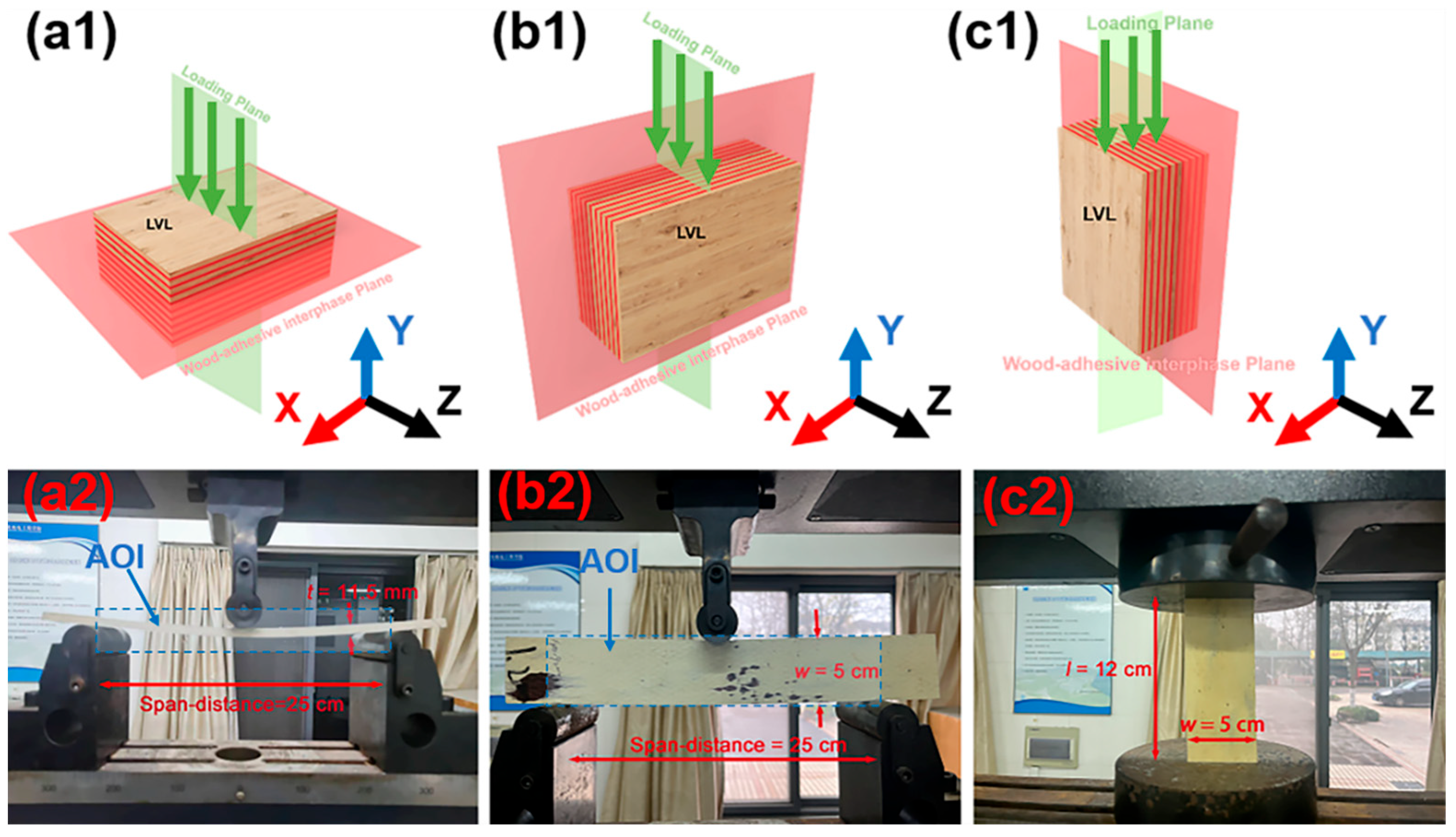
2.3.1. Static Mechanical Properties of LVL

The ultimate strength of LVL subjected to different loading regimes (as shown in Figure 1) were determined at a constant temperature and RH (25 °C and 55%) to provide the basic data for following creep, according to a standing standard [25]. In this work, a universal mechanical testing machine (Instron 5960, Boston, MA, USA) with a uniform loading speed of 2 mm·s−1 was applied to record the stress/strain curves of LVL, and the stress corresponding to the highest point in the curves was recorded. An auto-recording system applied to the universal mechanical testing machine can reveal the real-time changes in loading (F), and record the maximum loading (Fmax). The stress (δ) and deformation (ε) of LVL can also be obtained in real time by inputting the dimensions of specimens. The relationships between F and δ are listed in Equations (1) and (2), which correspond to bending and compression, respectively. In Equations (1) and (2), l, w, and t refer to the length, width, and thickness of specimens, respectively. By using Fmax, the ultimate strength can be calculated using Equations (1) and (2). The presented ultimate strength and stress/strain curve for each loading regime in this work was averaged from six replicates to minimize any undesired errors.
δ = 3 × F × l 2 × w × t 2
δ = F w × t

2.3.2. Creep Behaviors of LVL

The creep procedures of LVL exhibit a time scale of up to decades, and thus, assessing the long-term creep behavior of LVL by means of the conventional creep test is extremely time-consuming and impractical. Accelerated testing using the stepped iso-stress method (SSM) as in this work provides a time-efficient methodology for long-term creep characterization and the evaluation of the creep strain dissipation [26]. Previous studies have demonstrated the feasibility of SSM in the prediction of long-term creep behaviors [27]. Here, we focused on the creep strain dissipation of LVL facing different loading regimes. Therefore, SSM was used to achieve efficient characterization. The most commonly applied test time in SSM is 2–5 h. According to this, we chose 120 min as the testing time.
The 120 min creep behaviors of LVL were determined using the same universal mechanical testing machine as in the former analysis. The specimens for bending creep (flat-wise and edge-wise bending) exhibited uniform dimensions of 40 cm (l) × 5 cm (w) × 11.5 mm (t). The applied span-distance was 25 cm. For compression creep, the dimensions of specimens were 12 cm (l) × 5 cm (w) × 11.5 mm (t). We chose 30%, 50%, and 70% of the ultimate strength as the creep stress levels for each loading regime, respectively. Based on the auto-recorded loading, we can obtain the creep stress levels corresponding to 30%, 40%, and 50% of the ultimate strength using Equations (1) and (2). The creep compliance of LVL that represents the temporal change in strain under unit stress can be obtained by Equation (3) [13], where J(t) refers to the creep compliance (MPa−1), εt represents the strain at time t, and σ0 is the applied creep stress (MPa). The creep behaviors of LVL were further evaluated based on the creep coefficient (φ), as defined in Equation (4), where εinst corresponds to the instantaneous strain [28].
J ( t ) = ε t σ 0
φ = ε t ε i n s t ε i n s t

2.3.3. Creep Strain Dissipation and the Resultant Plastic Deformation of LVL

Digital image correlation (DIC) analysis was exploited to reveal the strain cartographies in the X-Y plane (as indicated in Figure 1(a1–c1)) of LVL at 50% of the ultimate strength. The relative strain of LVL can be obtained by evaluating the movement of randomly distributed pixels. Here, we monitored the strain dissipation of flat-wise and edge-wise bent LVL in the region pinpointed by the blue frames in Figure 1(a2,b2), and the corresponding dimensions of the area of interest (AOI) were 25 cm × 11.5 mm and 25 cm × 5 cm, respectively. For the axial compression creep of LVL, the dimensions of AOI were 12 cm × 11.5 mm, located on the edge side of the specimen. The pixels were randomly distributed through painting on the relevant AOIs, and the average distance between adjacent pixels was 0.3 ± 0.1 mm. A Vic-2D measurement system (Correlated Solutions, Irmo, SC, USA) and the associated commercial software package (VIC-2D HR system) were utilized in this work. Based on this, the creep strain in the X-X (vertical to the loading plane) and Y-Y (parallel to the loading plane) directions can be decoupled from the obtained strain cartographies. The camera resolution for the DIC analysis was 2448 × 2048, suggesting a strain resolution of ~20 micro-strains. Snapshots with a resolution of ~20 μm were captured every 120 s using two charge-coupled device cameras. Two Lowel Pro LED lights were utilized to illuminate the speckle patterns and thus enhance the contrast. Ultra-depth-of-field microscopy (VHX-7000N, Keyence, Shanghai, China) was utilized to evaluate the morphologies of LVL after 120 min creep at 50% of the ultimate strength.

3. Results and Discussion

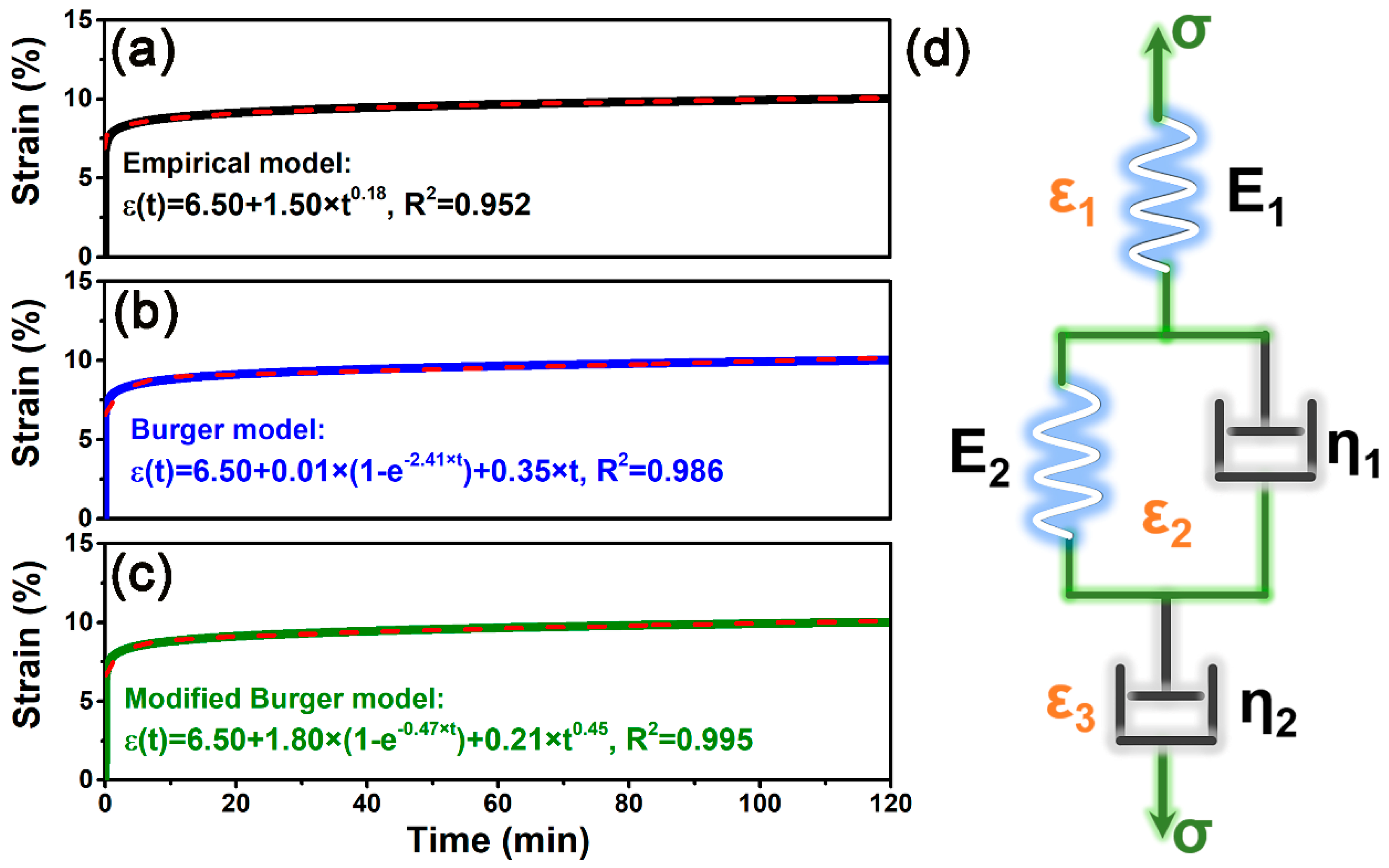
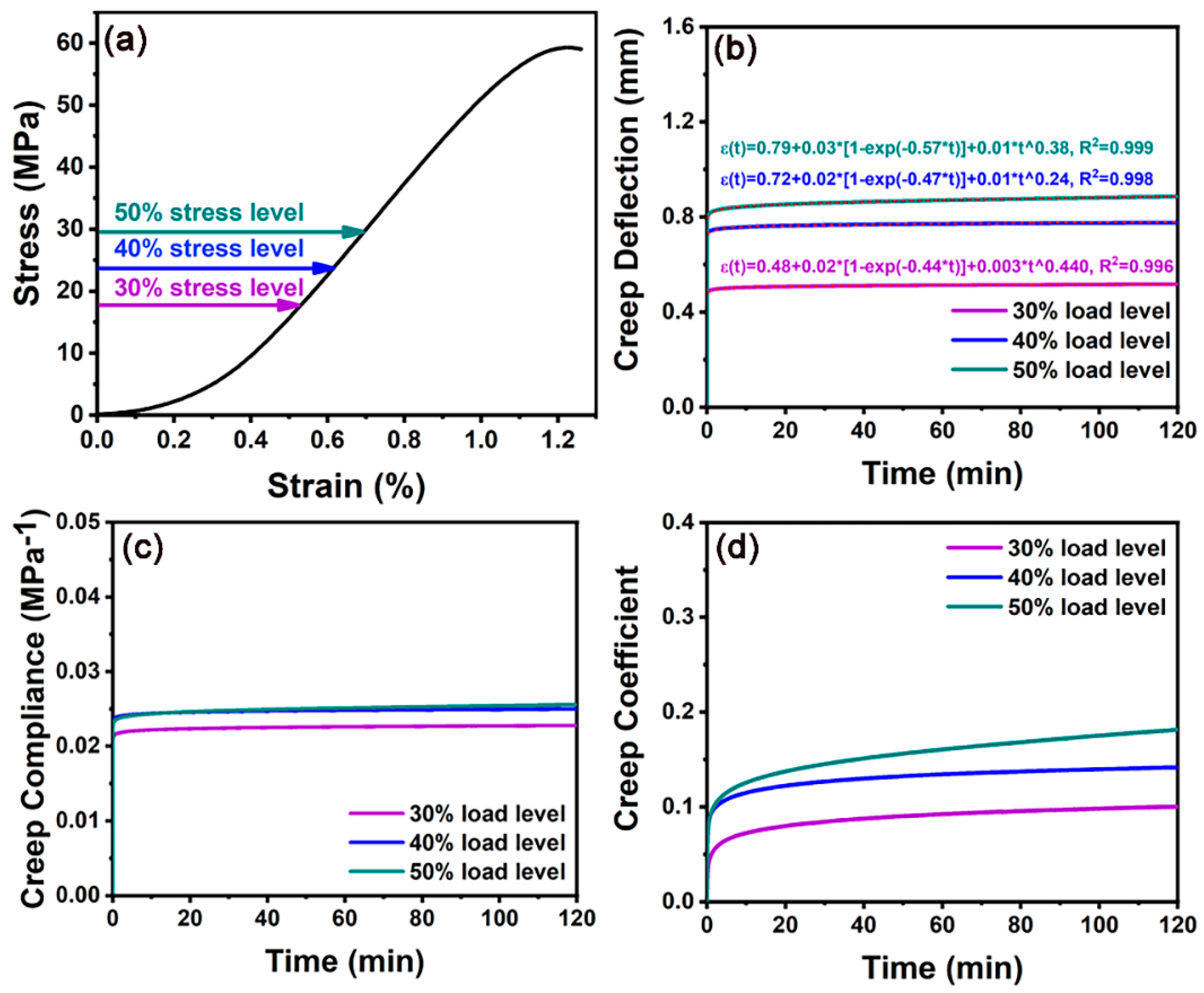
3.1. Comparison between the Fitting Accuracy of Creep Numerical Models

Numerical models have been widely applied for understanding the viscoelastic behaviors of wood and wood-based products [29]. The Findley power law model (as described in Equation (3)) is an empirical mathematical model that provides satisfying fitting results regarding the creep behaviors of polymer composites [30]. As presented in Equation (5), δ(t) refers to the creep deflection at time t, and δ0 stands for stress-dependent instantaneous creep deflection. m and β in Equation (5) represent the stress-independent material constant and the stress-dependent coefficient, respectively [31]. The Findley power law model pays more attention to the elastic and viscoelastic stages of viscoelastic materials, while it neglects the viscous deformation of materials, leading to lower fitting accuracy [32]. Figure 2a presents the fitting results of the flat-wise bending creep curves of LVL at 50% of the ultimate strength, yielding a fitting accuracy (R2) of 0.952 corresponding to the Findley power law model. For comparison, the Burgers model (as shown in Equation (6)) was exploited to fit the same creep curve, suggesting an elevated R2 of 0.986 (Figure 2b). The Burgers model comprises a Maxwell spring/dashpot and Kelvin spring/dashpot, as shown in Figure 2d. As displayed in Equation (6), σ0 represents the creep stress, and t denotes the creep time. Em and ηm correspond to the modulus and viscosity of the Maxwell spring and dashpot, respectively. Ek and ηk refer to the modulus and viscosity of the Kelvin spring and dashpot, respectively [33].
δ t = δ 0 + β × t m
ε t = σ 0 E m + σ 0 E k × 1 e E k η k × t + σ 0 η m × t
ε t = σ 0 E m + σ 0 E k × 1 e E k η k × t + σ 0 η m × t m
In order to further improve the creep fitting accuracy of the viscosity stage of LVL, we transformed the linear term (t) in the Burgers model into a power one (tm), as displayed in Equation (7). The coefficient m exhibits no physical significance, and it was only used to transform the viscous phase from a linear function to a nonlinear one, which is more consistent with the whole process of the creep deformation of wood [34]. As displayed in Figure 2c, creep curve fitting achieves higher accuracy compared with the former analysis, with R2 up to 0.995. Therefore, the modified Burgers model was selected to fit the creep curves in this study.

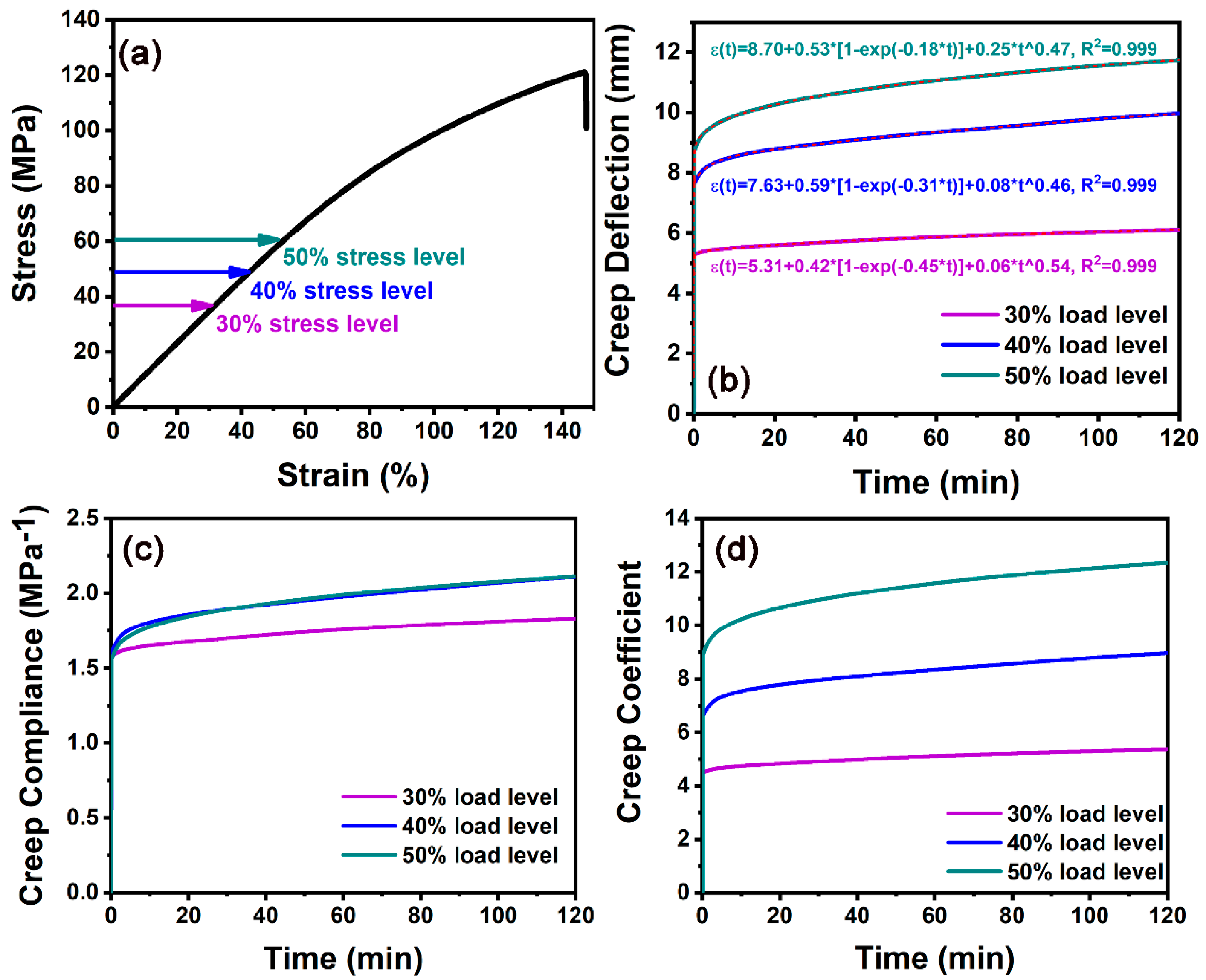
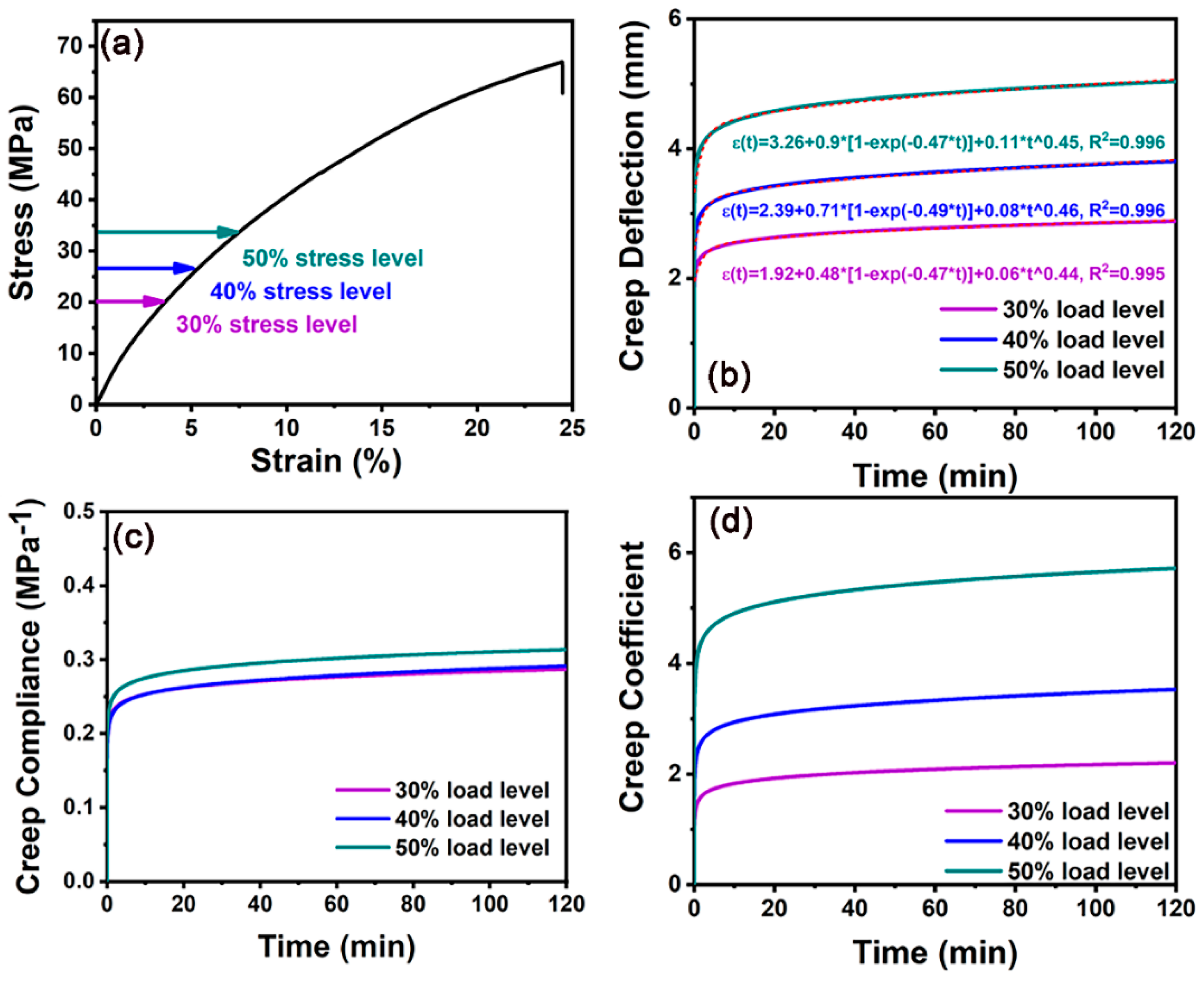
3.2. Creep Behaviors of LVL Subjected to Various Loading Regimes

As shown in Figure 3a, the average bending strength of LVL was 120.7 ± 5.2 MPa, which is much higher than that of bulk poplar (54.5 ± 4.7 MPa), demonstrating the suitability of LVL as an engineered wood product for timber architectures. In this work, 30%, 40%, and 50% of the ultimate strength were selected as the flat-wise bending creep stress levels. As shown in Figure 3b, the creep of LVL was a long-term process, and the creep deformation gradually increased with time. Under 50% of the ultimate strength, the creep deflection of LVL can reach 11.6 mm, indicating obvious deformation. The modified Burgers model was used to fit the creep behavior of LVL under different loads, and the fitting curve was highly correlated with the experimental curves (R2 up to 0.999). The investigation into the deformation rate of LVL revealed that the creep deformation rate slowly decreases with time, after rapid deformation in the early stage (0–5 min), demonstrating a nonlinear process of creep deformation in LVL [28,35]. Figure 3b also indicates the non-linear amplification of the creep deflection as creep stress elevates. It was worth noting that the creep deflection of the viscoelastic stage of LVL is significantly higher when subjected to 50% of the ultimate strength, compared with that subjected to 30% and 40% of the ultimate strength. Meanwhile, the hysteresis of transient deformation into viscoelastic deformation when LVL was subjected to flat-wise bending can be observed in Figure 3b, and it was closely related to the creep stress levels. As displayed in Figure 3c,d, the creep compliance and creep coefficient of flat-wise bent LVL were consistent with the creep deflection as time advanced, i.e., they were positively correlated with the elevated creep stress levels. The creep compliances of the flat-wise bent LVL at 40% and 50% of the ultimate strength stabilized at ~2.2 MPa−1, also suggesting significant deformation of the LVL.
Figure 4 shows the stress/strain curves of LVL under edge-wise bending and the corresponding creep curves under 30%, 40%, and 50% of the ultimate strength. The modified Burgers model demonstrated suitability for numerically fitting the edge-wise bending creep curves of LVL (R2 ≥ 0.995). It is also shown in Figure 4b that the creep deflection–time curve of LVL facing edge-wise bending is non-linear, and the amplification of creep deflection was particularly obvious under different stress levels. The LVL creep deflection was 5.2 mm when subjected to 50% of the ultimate strength, which was almost twice higher than that at 30% of the ultimate strength. As displayed in Figure 4b, the hysteresis of transient deformation into viscoelastic deformation was obvious for all chosen creep stress levels, suggesting the substantial plastic deformation of LVL subjected to edge-wise bending creep [36,37,38]. The brittle fracturing of PF adhesive can be a major trigger for the plastic deformation of LVL due to the direct contact at the wood–adhesive interface and loading plane in the edge-wise bending of LVL [39]. The creep compliance of edge-wise bent LVL at 50% of the ultimate strength was ~0.3 MPa−1, which was lower than that corresponding to flat-wise bending creep by an order of magnitude. This suggests a discrepancy in the mechanical robustness of LVL subjected to flat/edge-wise bending creep. The penetration of rigid PF adhesive resulted in the elevated mechanical performance of the wood–adhesive interface, guaranteeing less deformation of LVL in direct contact with the loading plane as in edge-wise bending.
It is shown in Figure 5 that the axial compression creep behaviors of poplar LVL are different from the bending creep, as represented by the low the creep deflection of LVL (0.82 mm). This could be related to the high mechanical strength of the paraxial and spiral arrangement of microfibrils in the wood cell wall [40,41]. The modified Burgers model still had a high fitting accuracy for the compressive creep experimental data of LVL (R2 ≥ 0.996), as shown in Figure 5b. The instantaneous creep deformation was dominant in the axial compression creep of LVL at lower stress levels (30% and 40% of the ultimate strength), and the prolongation of time had no obvious effect on the compressive creep deflection of LVL. When LVL was in the viscoelastic stage, its creep deflection curve was almost parallel to the X-axis. The creep compliance of axial compressed LVL at 50% of the ultimate strength was ~0.025 MPa−1, benefiting from the excellent axial rigidity of the wood cell wall (Figure 5c). The creep coefficient of LVL (as shown in Figure 5d) confirmed the minor creep deflection at lower stress levels. However, 50% of the ultimate strength led to an increasing creep coefficient, suggesting the continuous deformation of LVL.
Based on the description of the creep behaviors, through the modified Burgers model, we can further calculate the modules of the Maxwell and Kelvin springs, as listed in Table 1. This table reveals the higher modules of Maxwell and Kelvin springs when LVL is subjected to axial compression creep, which can be attributed to the evident rigidity of the cell wall that benefits from the paraxially arranged cellulose microfibrils.

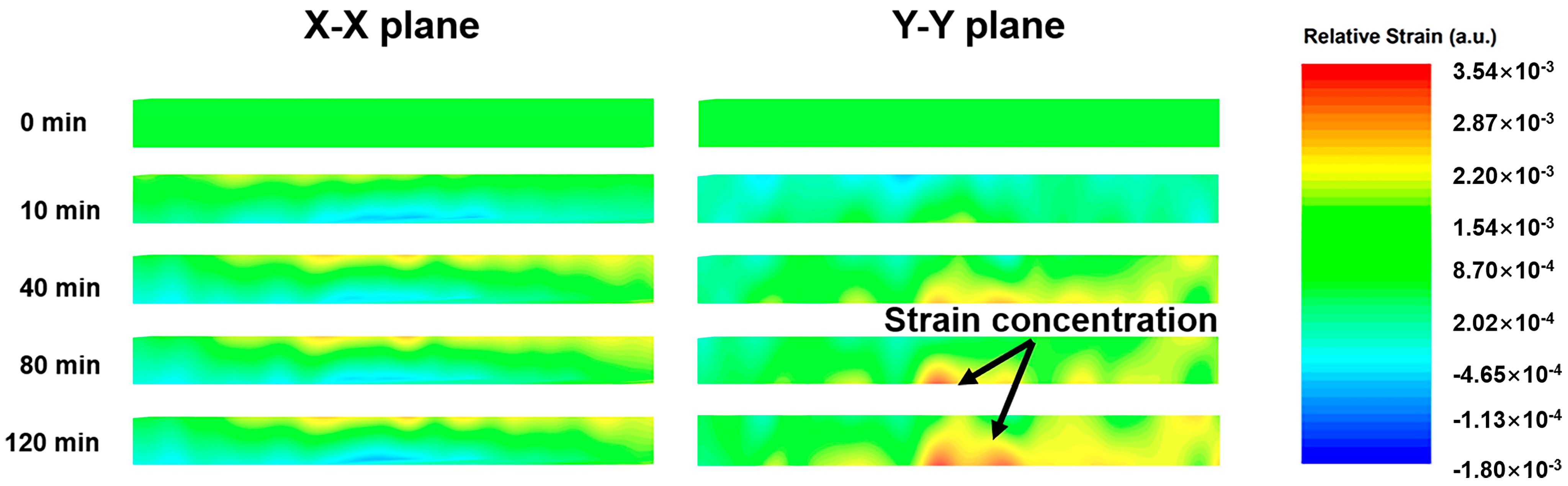
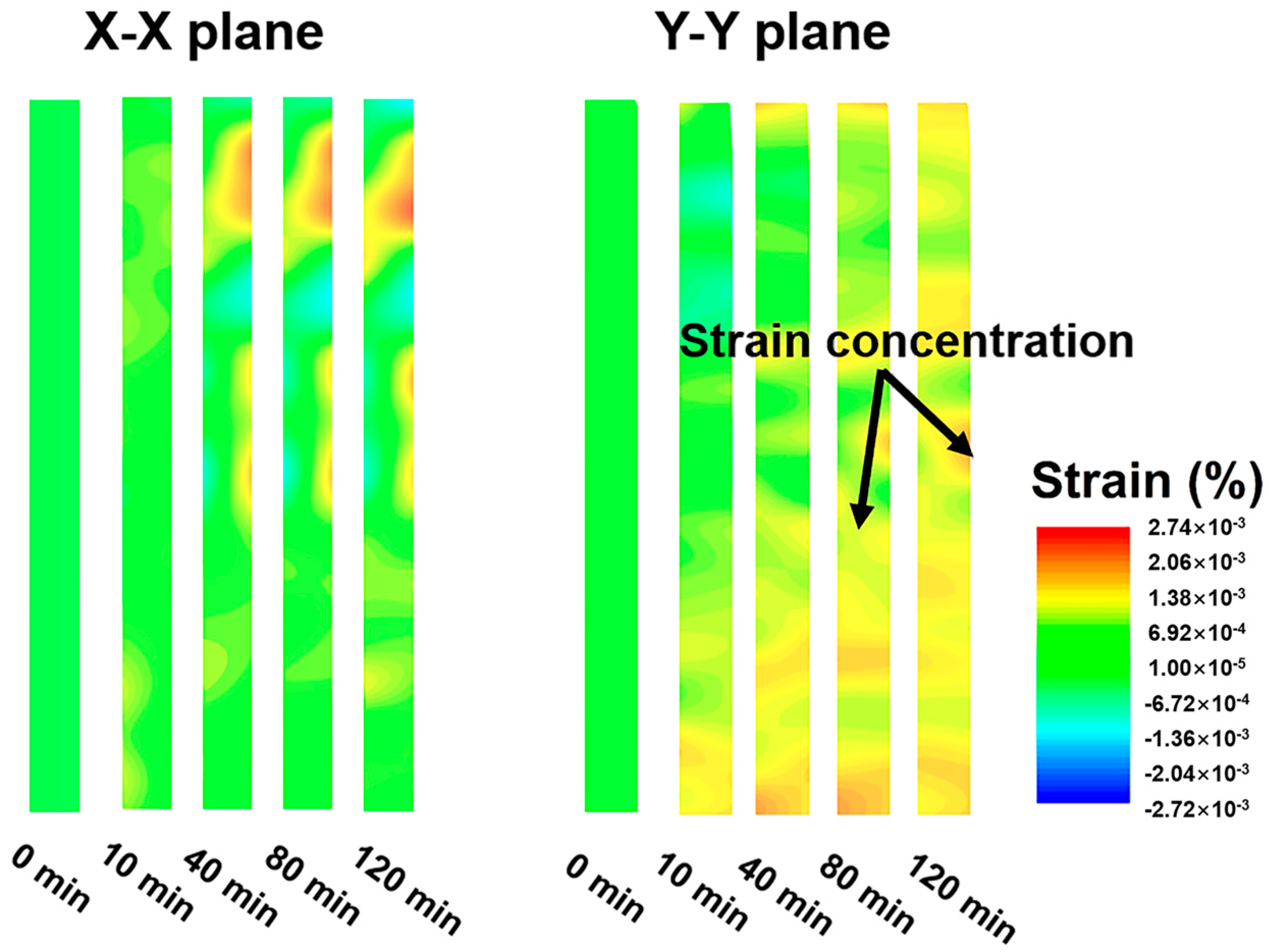
3.3. Creep Strain Dissipation of LVL

In order to reveal the creep strain dissipation of LVL and further understand the creep behavior of LVL under different loading regimes, a uniform creep stress level of 50% of the ultimate strength was selected, and DIC was used to monitor the real-time stress/strain evolution of LVL during the creep process. As displayed in Figure 6, creep strain accumulation of the flat-wise bent LVL was generated on the bottom surface of the LVL as time advanced, and the highest relative strain was observed at a time of 120 min. By decoupling the strain that dissipated along the X-X and Y-Y directions, the creep strain dissipation pathway of the flat-wise bent LVL was demonstrated to be coupled with being parallel and vertical to the loading plane. As indicated in Figure 6, the creep strain dissipation along the Y-Y plane transited the wood–adhesive interface and further extended to the bottom surface of the LVL. Compared with this, the creep strain in the X-X plane dissipated parallel to the wood–adhesive interface, and then, accumulated on the surface or sub-surface of the LVL. The highest creep strain observed in the X-X plane was 3.5 × 10⁻³, which is close to the strain in the Y-Y plane (4.0 × 10⁻³), further confirming the coupled creep strain dissipation of LVL subjected to flat-wise bending creep.
During edge-wise bending creep in LVL, the loading plane directly contacted the wood–adhesive interface, and the strain dissipation was mainly parallel to the Y-Y plane, as shown in Figure 7. The creep strain was observed to be confined in the top half region of the LVL, and the highest strain in the Y-Y plane was 4.0 × 10⁻³. The creep strain accumulation along the X-X plane was less than that in the Y-Y plane, indicating the highest strain of 2.8 × 10⁻³. The strain exhibits same direction as the loading, while the contraction/expansion of materials leads to the minor dissipation of strain in other directions [22,42]. This work confirmed the coupled creep strain dissipation of LVL subjected to edge-wise bending creep, and the comparison of the creep strain dissipation also indicated that the dominant dissipation pathway of the edge-wise bent LVL was in the Y-Y direction, i.e., parallel to the loading plane.
Figure 8 shows the creep strain dissipation of LVL under 50% of the ultimate strength when subjected to axial compression creep. Compared with the bending creep (i.e., flat-wise and edge-wise), the axial compression creep of LVL exhibited a completely different stress/strain distribution. Creep strain accumulation along the X-X plane can be observed in the top half region of the LVL as the time exceeds 40 min. The highest creep strain was observed to be 2.7 × 10⁻³ in the X-X plane, indicating the obvious expansion of the LVL. Despite this, creep strain dissipation was demonstrated to be more obvious in Y-Y plane (i.e., being parallel to the wood–adhesive interface), indicating the dominance of Y-Y plane in creep strain dissipation. The strain concentration can be observed to be situated in the bottom half of the LVL.
The aforementioned analysis demonstrated coupled creep strain dissipation along the X-X and Y-Y planes as the LVL subjected to creep. It thus underscores the significance of creep responses of the wood–adhesive interface to the macroscopic creep behaviors of LVL. As an important link in LVL, the wood–adhesive interface is responsible for strain dissipation [43]. The rigid adhesive possesses fast and substantial plastic deformation when subjected to creep compared with wood cell walls, leading to different creep responses of the wood–adhesive interface. Therefore, the macroscopic creep deformation of LVL exhibits direct correlations with the corresponding properties of the wood–adhesive interface. The observed creep strain dissipation of LVL sheds light on future methodologies to improve the creep resistance of LVL by improving the interfacial interlock and the local creep resistance of the wood–adhesive interface. Through interfacial engineering, such as plasma and surficial sanding [19,44], the interfacial interlock of the wood–adhesive interface can be improved, which can be helpful for the penetration of adhesive into the wood cell walls, and thus, enhance the local creep resistance of the wood–adhesive interface.

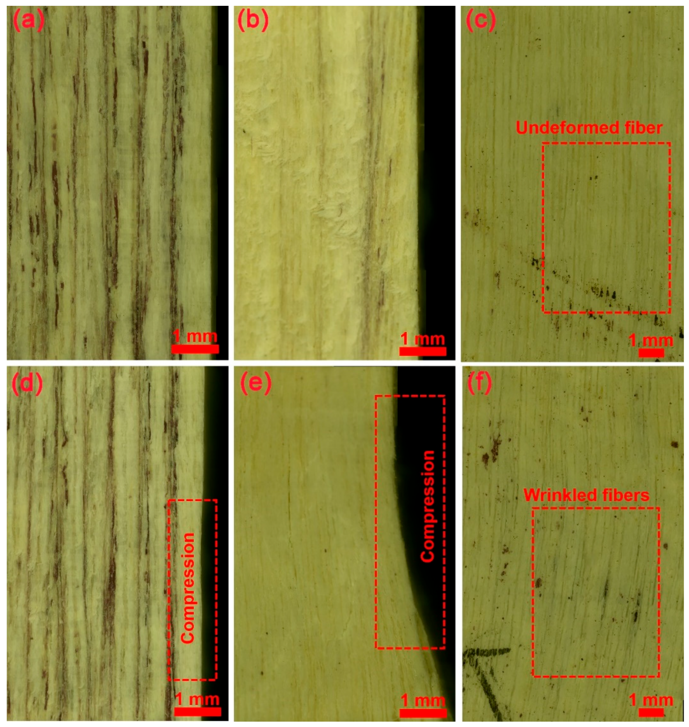
3.4. Plastic Creep Deformation of LVL

Beyond the investigation into the creep strain evolution of LVL under different loading regimes, the morphology of the LVL before and after creep under 50% of the ultimate strength was also observed through ultra-depth-of-field microscopy to provide supplementary insights into the creep behaviors of LVL. As displayed in Figure 9a,d, despite the large deflection during the creep test, the plastic deformation of the LVL was minor after 120 min flat-wise bending creep, which can be attributed to the recovery of the wood. In contrast, the plastic deformation of the LVL after 120 min edge-wise bending creep was obvious (Figure 9b,e), and the location of deformation corresponds to the strain concentration site, as revealed before. Considering the inconspicuous difference in the stress relaxation and creep resistances of wood cell walls in the tangential and radial directions [9,45,46,47], one plausible trigger for the obvious plastic deformation of the LVL after edge-wise bending creep can be speculated to be the failure of the wood–adhesive interface. The viscoelastic wood cell walls and brittle PF adhesive exhibit substantial differences in their creep responses, and the PF adhesive is more sensitive to creep stress. Thus, creep-provoked fracture at the wood–adhesive interface can occur when it is in direct contact with the loading plane. For assessing the axial compression creep of the LVL, wrinkled and cracked wood fibers can also be observed (Figure 9c,f). This is also associated with the creep strain concentration in the Y-Y plane of the LVL, as mentioned before. Here, we found two possible causes for the creep failure of the LVL, i.e., the failure of the wood–adhesive interface and the deformation of wood fibers, and both of them can be attributed to the creep strain dissipation that coupled along the X-X and Y-Y planes of the LVL.

4. Conclusions

The creep behaviors and corresponding strain dissipation of LVL subjected to flat-wise bending, edge-wise bending, and axial compression creep were investigated in this paper to advance our understanding of the creep deformation of LVL facing multiple applications in timber architectures. The major outcomes are as follows.
(1)
The results demonstrated obvious loading regime dependency of the creep behaviors of LVL, along with nonlinearity in all observed creep deformations of LVL, as the creep stress levels were elevated from 30% to 50% of the ultimate strength.
(2)
The flat-wise and edge-wise bent LVL displayed coupled dissipation of creep strain that concentrates on the surface and sub-surface of the LVL, suggesting that the creep strain dissipates along and transits the wood–adhesive interface as the LVL is subjected to flexure. In contrast, the creep dissipation was majorly uniform in the axial compression creep of the LVL along with the wood–adhesive interface.
(3)
The plastic deformation of the flat-wise bent LVL was minor, benefiting from the wood recovery. Significant plastic deformation can be observed after edge-wise bending and axial compression creep due to the direct contact between the loading plane and the wood–adhesive interface. Due to the substantial differences in the creep responses of the wood cell wall and adhesive, premature failure of the wood–adhesive interface can trigger accelerated creep deformation and resultant plastic deformation after creep. Meanwhile, cracked and wrinkled fibers could be another reason for the plastic deformation after creep at 50% of the ultimate strength.
We believe this work provides insights into the creep deformation of LVL and underscores the significant role of the wood–adhesive interface in the creep behaviors of LVL. It is thus beneficial for advancing the creep resistance and long-term safety of LVL-based engineered wood products by introducing interfacial engineering, i.e., plasma treatment and surficial sanding.

Author Contributions

Conceptualization, Y.C.; Methodology, S.X., Y.C., X.C., X.L. and R.T.; Software, P.Y., X.L. and R.T.; Validation, Y.C.; Formal analysis, Y.C.; Investigation, S.X., Y.C., P.Y. and R.T.; Resources, X.C. and Y.Y.; Data curation, S.X., P.Y., X.L. and R.T.; Writing—original draft, Y.C.; Writing—review & editing, Y.C.; Supervision, Y.C. and Q.W.; Project administration, Y.Y. and Q.W.; Funding acquisition, Y.Y. and Q.W. All authors have read and agreed to the published version of the manuscript.

Funding

The authors gratefully acknowledge funding support from the National Natural Science Foundation of China (32201493, 31870548, and 32101603), the Scientific Research Development Foundation of Zhejiang A&F University (2022LFR023), and the Research Foundation of Talented Scholars of Zhejiang A&F University (2020FR070).

Data Availability Statement

The data presented in this study are available on request from the corresponding author.

Conflicts of Interest

The authors declare that they have no known competing financial interests or personal relationships that could have appeared to influence the work reported in this paper.

References

  1. Yang, F.; Jin, C.; Wang, S.; Wang, Y.; Wei, L.; Zheng, L.; Gu, H.; Lam, S.S.; Naushad, M.; Li, C.; et al. Bamboo-based magnetic activated carbon for efficient removal of sulfadiazine: Application and adsorption mechanism. Chemosphere 2023, 323, 138245. [Google Scholar] [CrossRef] [PubMed]
  2. Dong, Y.; Tan, Y.; Wang, K.; Cai, Y.; Li, J.; Sonne, C.; Li, C. Reviewing wood-based solar-driven interfacial evaporators for desalination. Water Res. 2022, 223, 119011. [Google Scholar] [CrossRef] [PubMed]
  3. Dong, Y.; Wang, K.; Li, C.; Cai, Y.; Li, J.; Lam, S.S.; Sonne, C. High-performance and scalable wood-based solar-driven interfacial evaporator with corru-gated structure for continuous desalination. J. Clean. Prod. 2023, 418, 138024. [Google Scholar] [CrossRef]
  4. Li, C.; Ye, H.; Ge, S.; Yao, Y.; Ashok, B.; Hariram, N.; Liu, H.; Tian, H.; He, Y.; Guo, G.; et al. Fabrication and properties of antimicrobial flexible nanocomposite polyurethane foams with in situ generated copper nanoparticles. J. Mater. Res. Technol. 2022, 19, 3603–3615. [Google Scholar] [CrossRef]
  5. Zhang, X.; Popovski, M.; Tannert, T. High-capacity hold-down for mass-timber buildings. Constr. Build. Mater. 2018, 164, 688–703. [Google Scholar] [CrossRef]
  6. Cornwall, W. Tall timber. Science 2016, 353, 1354–1356. [Google Scholar] [CrossRef]
  7. Gong, M. Engineered Wood Products for Construction; IntechOpen: London, UK, 2022. [Google Scholar]
  8. Sun, X.; He, M.; Li, Z. Novel engineered wood and bamboo composites for structural applications: State-of-art of manufacturing technology and mechanical performance evaluation. Constr. Build. Mater. 2020, 249, 118751. [Google Scholar] [CrossRef]
  9. Xing, D.; Wang, X.; Wang, S. Temperature-Dependent Creep Behavior and Quasi-Static Mechanical Properties of Heat-Treated Wood. Forests 2021, 12, 968. [Google Scholar] [CrossRef]
  10. Hsieh, T.-Y.; Chang, F.-C. Effects of moisture content and temperature on wood creep. Holzforschung 2018, 72, 1071–1078. [Google Scholar] [CrossRef]
  11. Kuzman, M.K.; Klarić, S.; Barčić, A.P.; Vlosky, R.P.; Janakieska, M.M.; Grošelj, P. Architect perceptions of engineered wood products: An exploratory study of selected countries in Central and Southeast Europe. Constr. Build. Mater. 2018, 179, 360–370. [Google Scholar] [CrossRef]
  12. Musselman, E.S.; Dinehart, D.W.; Walker, S.M.; Mancini, M.L. The effect of holes on the creep behavior and flexural capacity of laminated veneer lumber (LVL) beams. Constr. Build. Mater. 2018, 180, 167–176. [Google Scholar] [CrossRef]
  13. Fu, H.; Dun, M.; Wang, H.; Wang, W.; Ou, R.; Wang, Y.; Liu, T.; Wang, Q. Creep response of wood flour-high-density polyethylene/laminated veneer lumber coextruded composites. Constr. Build. Mater. 2020, 237, 117499. [Google Scholar] [CrossRef]
  14. Kamau-Devers, K.; Miller, S.A. Using a micromechanical viscoelastic creep model to capture multi-phase deterioration in bio-based wood polymer composites exposed to moisture. Constr. Build. Mater. 2022, 314, 125252. [Google Scholar] [CrossRef]
  15. Jia, N.; Jin, W. Experiment on the Bending Creep Stress Levels Correlation of Laminated Veneer Lumber. For. Sci. Technol. 2008, 3, 38–40. [Google Scholar]
  16. Sandhaas, C.; Sarnaghi, A.K.; van de Kuilen, J.-W. Numerical modelling of timber and timber joints: Computational aspects. Wood Sci. Technol. 2020, 54, 31–61. [Google Scholar] [CrossRef]
  17. Yu, Z.; Fan, M. Short- and long-term performance of wood based panel products subjected to various stress modes. Constr. Build. Mater. 2017, 156, 652–660. [Google Scholar] [CrossRef]
  18. Cao, Y.; Zhang, T.; Yang, P.; Chen, M.; Chen, W.; Wang, S.; Zhou, X. Fast atmospheric plasma treatment of LLDPE film for preparing formaldehyde emission-free plywood. Eur. J. Wood Wood Prod. 2020, 78, 705–714. [Google Scholar] [CrossRef]
  19. Cao, Y.; Zhang, W.; Yang, P.; Li, X.; Zhang, T.; Chen, W.; Wang, S.; Zhou, X. Comparative investigation into the interfacial adhesion of plywood prepared by air spray atomization and roller coating. Eur. J. Wood Wood Prod. 2021, 79, 887–896. [Google Scholar] [CrossRef]
  20. Fan, Z.; Xu, S.; Liu, X.; Cao, Q.; Cao, Y.; Wu, X. Aspergillus niger infection weakens the robustness of bamboo-adhesive interphases by damaging the adhesive and detaching the interfacial bonding. Ind. Crop. Prod. 2023, 204. [Google Scholar] [CrossRef]
  21. Zhou, X.; Cao, Y.; Yang, K.; Yu, P.; Chen, W.; Wang, S.; Chen, M. Clean plasma modification for recycling waste plastic bags: From improving interfacial adhesion with wood towards fabricating formaldehyde-free plywood. J. Clean. Prod. 2020, 269, 122196. [Google Scholar] [CrossRef]
  22. Sözen, E.; Kayahan, K.; Bardak, T.; Bardak, S. The effects of the moisture content of laminated veneer lumber on bending strength and deformation determination via two-dimensional digital image correlation. Proc. Inst. Mech. Eng. Part C J. Mech. Eng. Sci. 2021, 235, 5603–5615. [Google Scholar] [CrossRef]
  23. Wang, J.B.; Lam, F.; Foschi, R.O. Duration-of-load and creep effects in strand-based wood composite: Experimental research. Wood Sci. Technol. 2012, 46, 361–373. [Google Scholar] [CrossRef]
  24. Hadid, M.; Guerira, B.; Bahri, M.; Zouani, A. Assessment of the stepped isostress method in the prediction of long term creep of thermoplastics. Polym. Test. 2014, 34, 113–119. [Google Scholar] [CrossRef]
  25. Xu, J.-W.; Li, C.-C.; Liu, J.-W.; Chang, W.-C.; Chang, W.-S.; Wu, J.-H. Assessing the Long-Term Creep Behaviour of Hydrothermally Treated Japanese Cedar Wood Using the Short-Term Accelerated Stepped Isostress Method. Polymers 2023, 15, 4149. [Google Scholar] [CrossRef] [PubMed]
  26. Nie, Y.; Valipour, H. Experimental and numerical study of long-term behaviour of timber-timber composite (TTC) connections. Constr. Build. Mater. 2021, 304, 124672. [Google Scholar] [CrossRef]
  27. GB/T 14074-2017; Chinese National Standard for Adhesives. China National Standardization Administration Committee: Beijing, China, 2017.
  28. GB/T 9846-2015; Chinsese National Standard Plywood for General Use. China National Standardization Administration Committee: Beijing, China, 2015.
  29. Kazemi-Najafi, S.; Nikray, S.; Ebrahimi, G. A comparison study on creep behavior of wood-plastic composite, solid wood, and polypropylene. J. Compos. Mater. 2012, 46, 801–808. [Google Scholar] [CrossRef]
  30. Tscharnuter, D.; Muliana, A. Nonlinear response of viscoelastic polyoxymethylene (POM) at elevated temperatures. Polymer 2013, 54, 1208–1217. [Google Scholar] [CrossRef]
  31. Coppola, B.; Di Maio, L.; Incarnato, L.; Tulliani, J.-M. Preparation and Characterization of Polypropylene/Carbon Nanotubes (PP/CNTs) Nanocomposites as Potential Strain Gauges for Structural Health Monitoring. Nanomaterials 2020, 10, 814. [Google Scholar] [CrossRef]
  32. Faraz, M.; Besseling, N.; Korobko, A.; Picken, S. Characterization and Modeling of Creep Behavior of a Thermoset Nanocomposite. Polym. Compos. 2015, 36, 322–329. [Google Scholar] [CrossRef]
  33. Starkova, O.; Aniskevich, K.; Sevcenko, J.; Bulderberga, O.; Aniskevich, A. Relationship between the residual and total strain from creep-recovery tests of polypropylene/multiwall carbon nanotube composites. J. Appl. Polym. Sci. 2021, 138. [Google Scholar] [CrossRef]
  34. Hou, J.; Jiang, Y.; Yin, Y.; Zhang, W.; Chen, H.; Yu, Y.; Jiang, Z. Experimental study and comparative numerical modeling of creep behavior of white oak wood with various distributions of earlywood vessel belt. J. Wood Sci. 2021, 67, 57. [Google Scholar] [CrossRef]
  35. Huang, S.; Yan, L.; Kasal, B. Flexural behaviour of wood beams strengthened by flax-glass hybrid FRP subjected to hygro-thermal and weathering exposures. Constr. Build. Mater. 2023, 365, 130076. [Google Scholar] [CrossRef]
  36. Cisse, O.; Placet, V.; Guicheret-Retel, V.; Trivaudey, F.; Boubakar, M.L. Creep behaviour of single hemp fibres. Part I: Viscoelastic properties and their scattering under constant climate. J. Mater. Sci. 2015, 50, 1996–2006. [Google Scholar] [CrossRef]
  37. Fragiacomo, M.; Lukaszewska, E. Influence of the Construction Method on the Long-Term Behavior of Timber-Concrete Composite Beams. J. Struct. Eng. 2015, 141, 04015013. [Google Scholar] [CrossRef]
  38. Zheng, X.; Li, Z.; He, M.; Lam, F. Experimental investigation on the rheological behavior of timber in longitudinal and transverse compression. Constr. Build. Mater. 2021, 304, 124633. [Google Scholar] [CrossRef]
  39. Li, H.; Wang, S.; Zhang, X.; Wu, H.; Wang, Y.; Zhou, N.; Zhao, Z.; Wang, C.; Zhang, X.; Wang, X.; et al. Synthesis and Characterization of an Environmentally Friendly Phenol–Formaldehyde Resin Modified with Waste Plant Protein. Polymers 2023, 15, 2975. [Google Scholar] [CrossRef]
  40. Wang, D.; Xiang, E.; Fu, F.; Lin, L. The differences of viscoelastic properties between the secondary wall S2 layer and compound middle lamella of thermally treated wood. Wood Sci. Technol. 2022, 56, 1509–1525. [Google Scholar] [CrossRef]
  41. Adler, D.C.; Buehler, M.J. Mesoscale mechanics of wood cell walls under axial strain. Soft Matter 2013, 9, 7138–7144. [Google Scholar] [CrossRef]
  42. Li, W.; Mei, C.; Bulcke, J.V.D.; Van Acker, J. The effect of water sorption/desorption on fatigue deflection of OSB. Constr. Build. Mater. 2019, 223, 1196–1203. [Google Scholar] [CrossRef]
  43. Li, H.; Wang, Y.; Xie, W.; Tang, Y.; Yang, F.; Gong, C.; Wang, C.; Li, X.; Li, C. Preparation and Characterization of Soybean Protein Adhesives Modified with an Environmental-Friendly Tannin-Based Resin. Polymers 2023, 15, 2289. [Google Scholar] [CrossRef]
  44. Wolkenhauer, A.; Avramidis, G.; Hauswald, E.; Militz, H.; Viöl, W. Sanding vs. plasma treatment of aged wood: A comparison with respect to surface energy. Int. J. Adhes. Adhes. 2009, 29, 18–22. [Google Scholar] [CrossRef]
  45. Pan, Y.H.; Zhong, Z. Analysis of creep and modulus loss of the wood cell wall. Acta Mech. 2016, 227, 3191–3203. [Google Scholar] [CrossRef]
  46. Hoseinzadeh, F.; Zabihzadeh, S.M.; Dastoorian, F. Creep behavior of heat treated beech wood and the relation to its chemical structure. Constr. Build. Mater. 2019, 226, 220–226. [Google Scholar] [CrossRef]
  47. Guo, J.; Wang, C.; Li, C.; Liu, Y. Effect of Acetylation on the Physical and Mechanical Performances of Mechanical Densified Spruce Wood. Forests 2022, 13, 1620. [Google Scholar] [CrossRef]
Figure 1. Three loading regimes, i.e., flat-wise bending (a1), edge-wise bending (b1), and axial compression (c1), that apply to the characterization of the creep behaviors of LVL are indicated in an X-Y-Z coordinate system. The loading direction is also pinpointed using green arrows. The spatial positions of the wood–adhesive interface and loading plane are indicated. Corresponding photos of creep tests are presented in (a2c2), respectively, yielding a span-distance of 25 cm and the area of interest for strain analysis.
Forests 15 00179 g001
Figure 2. Fitting accuracy of creep curves of LVL using Findley power law model (a), Burgers model (b), and modified Burgers model (c). (d) Viscoelastic model of Burgers model.
Forests 15 00179 g002
Figure 3. The stress−strain (a), creep deflection−time (b), creep compliance−time (c), and creep coefficient−time (d) curves of the flat-wise bent LVL. The data presented in (a) were averaged from six replicates.
Forests 15 00179 g003
Figure 4. The stress−strain (a), creep deflection−time (b), creep compliance−time (c) and creep coefficient−time (d) curves of the edge-wise bent LVL. The data presented in (a) were averaged from six replicates.
Forests 15 00179 g004
Figure 5. The stress−strain (a), creep deflection−time (b), creep compliance−time (c), and creep coefficient−time (d) curves of the axial compressed LVL. The data presented in (a) were averaged from six replicates.
Forests 15 00179 g005
Figure 6. Creep strain dissipation along the X−X and Y−Y planes as LVL was subjected to flat-wise bending creep.
Forests 15 00179 g006
Figure 7. Creep strain dissipation along the X−X and Y−Y planes as LVL was subjected to edge-wise bending creep.
Forests 15 00179 g007
Figure 8. Creep strain dissipation along the X−X and Y−Y planes as LVL was subjected to axial compression creep.
Forests 15 00179 g008
Figure 9. The morphologies of LVL before and after 120 min creep. (a,d) Minor compression after flat-wise bending creep. (b,e) Obvious plastic compression after edge-wise bending creep. (c,f) Wrinkled fibers after axial compression creep.
Forests 15 00179 g009
Table 1. The calculated Em, Ek, and m corresponding to the creep behaviors of LVL subjected to different loading regimes.
Loading RegimesCreep Stress LevelsCreep Constants
Em (MPa)Ek (MPa)m
Flat-wise bending30% of the ultimate strength6.85669.920.54
40% of the ultimate strength6.3582.170.46
50% of the ultimate strength6.97114.340.47
Edge-wise bending30% of the ultimate strength10.4641.850.44
40% of the ultimate strength11.2137.730.46
50% of the ultimate strength10.2737.210.45
Axial compression30% of the ultimate strength28.44682.50.44
40% of the ultimate strength25.28910.00.24
50% of the ultimate strength28.80758.30.38
Disclaimer/Publisher’s Note: The statements, opinions and data contained in all publications are solely those of the individual author(s) and contributor(s) and not of MDPI and/or the editor(s). MDPI and/or the editor(s) disclaim responsibility for any injury to people or property resulting from any ideas, methods, instructions or products referred to in the content.

