1. Introduction
Primary wood processing in the forest begins with the fall of the tree, followed by the delimbing and transport to the wood store, up to the sorting of the wood. Timber sorting is carried out by cross-cutting the wood with a chain saw or saw blades. The primary wood processing group also includes: processor for the production of firewood and tilting log saw. This processor is equipped with a cutting mechanism (saw blade or saw chain) and a splitting mechanism (splitting wedge). Circular saws are used primarily for cross-cutting [
1]. It is actually a physical process that is significantly influenced by a large number of factors in various combinations. These factors include cutting and sliding speed. Knowledge of these factors is essential for achieving high economy, productivity and optimal machining quality. Gearing, which is the functional part of the tool itself, consists of a smaller or larger number of teeth arranged one behind the other so that their tips lie on the circumference of the cutting circle. Their basic function is to remove the chip from the machined material and its subsequent removal from the cutting gap. Due to the position of the cutting tool in relation to the cut fibers, cutting is divided into longitudinal, transverse and tangential [
2,
3]. In the manufacturing process of circular saw blade, a certain distribution of residual stress field should be generated inside it through tensioning process, like roll tensioning process, multispot pressure tensioning process and laser shock tensioning process. Tensioning process is beneficial to improve the dynamic stability of circular saw blade. Li and Zhang (2017) [
4]. studied the residual stress distribution of a roll-tensioned circular saw blade with ideal disk structure by finite element method. Generation and regulation mechanisms of the residual stress field of the circular saw blade after multispot pressure tensioning were analyzed by Li and Zhang 2019 [
5]. The research of cutting processes is of great importance, while today there are increasingly high demands for safety at work, automation, increasing the service life of cutting tools, reducing the energy consumption of machines and the associated cost reduction. One of the main parameters affecting the energy demand is the size of the cutting forces acting between the tool and the workpiece. The magnitudes of these forces can be expressed using theoretical relations or directly by experimental measurement, which provides the most accurate data [
4]. The parameters of wood cutting (energy consumption, dustiness and noise), the parameters of the resulting product (dimensional accuracy and the quality of the created surface) and the parameters of the manufactured chips (dimensions and particle size composition) depend on the shape of the teeth, the dimensions and number of teeth, the geometry of the cutting tool, the sharpness and technological conditions of the process, such as feed speed, feed force and cutting speed [
6,
7,
8]. Circular sawing is one of the most modern technologies in the woodworking industry. Saw blades are designed as universal sweeping blades for longitudinal or transverse cutting or trimming of all types of wood, soft or hard, dry or wet. The use of saw blades is different, especially with single or multiple cutting with a single or double shaft or in splitting machines. Circular sawing has been the center of attention of many researchers due to its wide use [
5].
Sawing is a composite process of shearing and cutting. With this process, we remove chips (sawdust), which happens when external cutting forces are applied, overcoming the strength of wood in compression and shear. The cutting wedges (teeth) of the saw blades are produced from different materials, such as tool steel EN 41 9418 (75Cr1), sintered carbide plates or stellite [
9]. During the wood cutting, the saw blade teeth overheat, which is caused by several factors. Many factors affect the sawing process. Understanding these factors and their mutual interactions will help us to fully understand the very principle of sawing. Familiarization with this issue will help us to eliminate undesirable effects with cross-sawing itself and losses of wood raw material and thus improve cross-sawing from an economic point of view. The woodworking industry in Slovakia is one of the few industries that develops on the basis of the domestic raw material base. Wood in our forests is still a reproducible raw material [
2,
6]. Currently, there is an effort towards ecological and complex utilization of the processed raw material. Recently, the modernization of machinery, which is conditioned by the development of new materials, has been highlighted in the global sawmill industry. So, we have to develop machines that are able to follow this development. The circular saw is one of the most used wood-splitting machines designed for transverse and longitudinal sawing of wood [
7,
10]. Svoreň et al. (2022) [
11] states that circular saws have an irreplaceable place in the longitudinal and transverse handling of lumber on the blank. It divides cross-cutting operations into two types: preliminary cross-cutting with excess and final cross-cutting to the required dimensions [
7,
8,
12]. The basic role in sawing is played by a rotating cutting tool—a saw blade perpendicular to the direction of the wood fibers. With transverse sawing, the secondary cutting edges of the teeth of the saw blade cut through the fibers and form the walls of the cutting joint. The main cutting edges form the bottom of the tooth groove [
6]. Currently, the most frequently used materials for the cutting edges of saw blades are the so-called sintered carbide plates, SC blades, and HSS tool steel [
4,
9,
10]. Saw blades with SC blades have 20 to 30 times higher cutting edge durability when sawing wood compared to HSS tool steel [
12]. The benefit of the work is the comparison of the tension on the teeth of the saw blade in the cut. An experimental measurement was carried out on a test device, where the processed data were evaluated and compared with theoretical data, which yielded interesting results, supported by voltage analysis.
2. Materials and Methods
Experimental measurements were carried out in the premises of the Technical University in Zvolen, specifically in the workshops intended for research and development. The measurements were carried out with the help of a measuring device, which consists of two main mechanisms, the cutting and feeding mechanisms (
Figure 1). The used tools of the main cutting mechanism, in which the value of the cutting speed was changed, were two types of saw blades of different construction (
Figure 2 and
Figure 3). The secondary feed mechanism consisted of a support driven by a threaded rod. This mechanism ensured that the workpiece was fed into the cut while changing the value of the feed rate. The division of the test prisms of two types of wood was performed by transverse sawing, i.e., perpendicular to the direction of the grain of the workpiece.
Experimental measurements were performed on a measuring device according to our proposed methodology, and the basic parameter of which was the recording of the torque.
The next step after obtaining the measured values was the calculation of the parameters needed to express the theoretical cutting force, which was subsequently compared with the real values of the experiment. Individual results of theoretical calculations of cutting force and actual values were recorded in the form of tables for better clarity.
In the selected CAD system PTC Creo Parametric 5.0., by defining the cutting forces converted to individual teeth in the cut, the 3D models of the saw blades were loaded when the corresponding cutting parameters were entered, and simulations were carried out. Their result was a picture of the tension on the saw blades, which were compared with each other.
2.1. Measuring Device and Its Components
The implementation of the experiment, which consisted of the transverse division of two selected types of wood with saw blades of the given dimensions, was carried out using an experimental device, and the individual components of which are described in
Figure 1. The most demanding requirements for machine tools are accuracy and precision, which mainly depend on the static deformation and dynamic behavior of the machine tool under variable cutting forces [
13,
14,
15,
16].
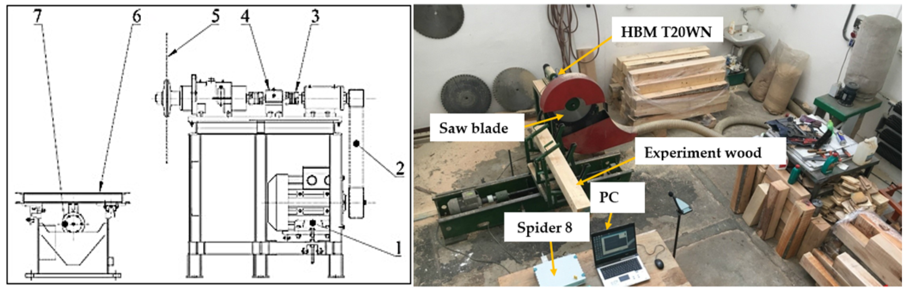
Figure 1.
Scheme of the experimental measuring device. 1—Electric motor of the cutting mechanism −7.5 kW, 2—belt transmission, 3—safety clutch Giflex GFLL, 4—sensor of torque and revolutions HBM T20WN, 5—saw blade, 6—fixing sliding carriage and 7—electromotor feeding mechanism 5.5 KW.
Figure 1.
Scheme of the experimental measuring device. 1—Electric motor of the cutting mechanism −7.5 kW, 2—belt transmission, 3—safety clutch Giflex GFLL, 4—sensor of torque and revolutions HBM T20WN, 5—saw blade, 6—fixing sliding carriage and 7—electromotor feeding mechanism 5.5 KW.
The work table (
Figure 1) contains a three-phase asynchronous electric motor (1) with a power of 7.5 kW. The torque is transmitted through the flat belt (2) and further through the bearing, safety clutch (3) GIFLEX GFLL—28 input clutch of the torque sensor (4), torque sensor HBM T20WN, output clutch of the torque sensor and spindle for the saw blade (5). The processed material is held in the sliding part (6) by means of a lever mechanism, which ensures sufficient clamping. The advance of the workpiece is provided by an electric motor (7) with a power of 5.5 kW. The signal from the torque sensor (4) is sent via cables to the Conmes Spider 8 measuring center, which is connected to a PC. The measured data is saved on the HDD of the computer (PC). Using the HBM T20WN (HBK Projektentwicklung GmbH & Co. KG, Hamburg, DE) torque sensor, we can also record the revolutions of the saw blade.
2.2. Preparation of Wood Samples
In the experiment, samples of Norway spruce with dimensions of 150 × 150 × 1500 mm were used. Individual samples were sawn from fresh spruce logs with dimensions of 3000 mm. The log was shortened using a chainsaw to half its length, which was transported using a transport cart to the MEMBER HTŽ 1000 (MEBOR d.o.o., Železniki, Slovenia) horizontal band saw, where the log was processed into samples of the required dimensions.
2.3. Moisture of the Samples
Moisture was measured using the gravimetric method, which consists of determining the weight of wet and dried wood by weighing. Two samples with dimensions of 50 × 50 × 20 mm were collected from the trees intended for the experiment. These samples were initially weighed to establish a reference weight value. Subsequently, the samples were dried using a MEMMERT UF 30 plus (Memmert GmbH + Co. KG, Schwabach, Germany) dryer, which was set to 110 °C. The samples were dried for 15 min. After this time, the samples were removed and reweighed [
4,
12].
2.4. Tools Used
In the experimental measurement, two types of saw blades from the manufacturer Pilana Tools (PILANA Wood s.r.o., Hulín, Czech Republic) were used, which underwent surface treatment by coating. A tool steel saw blade (
Figure 2) and a saw blade with SC blades (
Figure 3) were used for the experiment.
Table 1 lists the parameters of individual discs.
Figure 2.
Saw blade made of tool steel DIN 1.2003—HSS.
Figure 2.
Saw blade made of tool steel DIN 1.2003—HSS.
Saw blade in
Figure 2, 4A HSS is made of carbon tool steel 75Cr1 (DIN 1.2003). The hardness of the coated saw blade was measured with a Rockwell hardness tester, where the hardness value reached 43 HRC. The disc is intended for longitudinal and transverse cutting of soft and hard wood. It has 56 teeth, which are alternately spaced—1/3 of the thickness of the body of the saw blade on each side. Dimensions of the saw blade are 600 × 3.5 × 30, 56 KV 25°, where the blade diameter is 600 mm, diameter of the fixation hole is 30 mm with the accuracy H11 and 56 stands for teeth number [
12].
Figure 3.
Saw blade with SC blades in the shape of ATB (alternate top bevel).
Figure 3.
Saw blade with SC blades in the shape of ATB (alternate top bevel).
The blade is characterized by SC slices in the shape of ATB, which are soldered to the body of the saw blade (
Figure 3 and
Figure 4B). ATB is the bevel sequence that alternates from one tooth pitched from the left to one pitched from the right. This sequence continues around the whole blade. The angle of the bevel on the tooth is typically between 10 and 20 degrees. A bevel at 20 degrees will make a cleaner cut than one at 10 degrees. The hardness of SC wafers after coating reached a value of 43 HRC when measured on a Rockwell hardness tester. The disc has 54 alternating teeth, equipped with a chip limiter as well as expansion holes ending in a circular hole. Dilation grooves are designed in such a way as to prevent deformations of the disc under the action of centrifugal forces and heating by friction (workpiece—disc), which results in a high-quality cut with low noise of the tool. Dimensions of the saw blade are 600 × 5.2/3.5 × 30, 54 KV 25°, where the blade diameter is 600 mm, diameter of the fixation hole is 30 mm with the accuracy H11 and 54 stands for teeth number [
12].
2.5. Experimental Measurement
Individual measurements were performed at a cutting speed of 60, 70 and 80 m·s
−1 and a feed speed of 6, 8, 10 and 12 m·min
−1. The first step was to clamp the saw blade with SC blades on the shaft of the cutting mechanism. The disc was clamped between two flanges, which were secured by means of a lock washer and a nut. Subsequently, a spruce prism was inserted into the sliding support, and the position of which was determined using hand clamps equipped with compression springs. After clamping the tool and the workpiece, a cutting speed of 60 m·s
−1 and a feed speed of 6 m·min
−1 were set on the frequency converter, and six measurements were performed. Using the torque sensor, the values were recorded for the entire measurement, from which the five highest torque values were selected for each measurement, from which the average was calculated. Six measurements were then averaged and this value was later converted to cutting force for a given cutting speed and feed rate. Realization experimental measurements were performed for the selected wood spruce and for all feeds, the frequency of the cutting speed of the saw blade was increased to a value of 70 m·s
−1 and the procedure was repeated. Ending measuring at the highest cutting frequency and feed rate, the saw blade was replaced and measured again according to the procedure mentioned above [
17,
18,
19].
2.6. Calculation of Cutting Forces on Individual Teeth of the Saw Blade in the Cut
From the performed calculations, it is clear that both saw blades have a maximum of seven teeth in the engagement. The fact is that the first tooth in the cut takes the smallest chip and the last tooth the largest chip, which means that the individual teeth in the cut are not loaded with the same cutting force [
4,
20,
21,
22].
The cutting parameters of saw blades play a decisive role in the process of cutting wood, and they directly affect the quality of the machined surface and the service life of the tool [
23,
24]. Unlike metal, plastic or aluminum, wood tends to be heterogeneous and anisotropic. In fact, wood has three main directions: longitudinal, radial and tangential, which affects the partial results of experimental measurements [
25,
26]. The stress analysis was simulated for the cutting conditions
vc = 80 m·s
−1 and
vf = 12 m·min
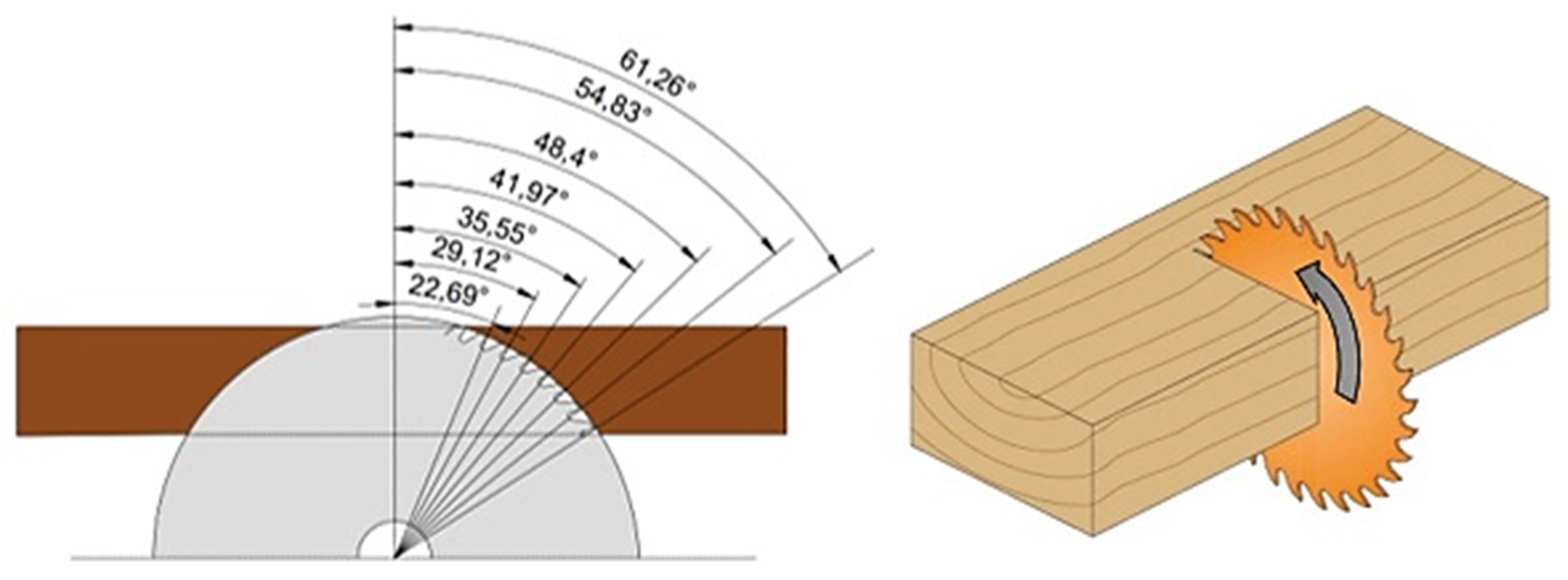
−1, which represents the values of the calculation of the cutting force per unit area of the cut. The angles of the individual teeth in the engagement were also determined, which can be seen in
Figure 5, and also confirms that the number of teeth in the engagement obtained by calculation coincides with reality.
Cutting force per unit of cutting area:
Cutting force acting on one tooth in engagement:
kc—cutting force per unit of cut area [N.mm−2],
bD—width of chip removed [mm],
e—cutting height [mm],
vf—feed rate [m·min−1],
vc—cutting speed [m·s
−1] [
14].
3. Results and Discussion
The stress analysis is carried out using the CAD system PTC Creo Parametric 5.0. Important data for performing the analysis are the values of the cutting forces,
Fc, acting on the individual teeth of the saw blade in the engagement, which are presented in the previous chapter. Using the size and direction of the cutting forces together with the boundary conditions, it was possible to implement a simulation in the evaluation of which the program includes the action of the gravitational force as well as the size of the centrifugal force for the specified cutting conditions. The results give an approximate idea of how big stresses can act on individual parts of the saw blade from the point of view of theory and practice [
10,
13,
14,
15,
16,
27,
28,
29].
Similar research in the field of stress analysis and transverse splitting of wood was carried out by several authors. Svoreň et al. (2022) [
11] dealt with the optimal conditions of the wood-sawing process, using circular saws, with regard to the quality of the wood surface. In the results, they evaluated the body of the saw blade and not the teeth penetrating the material. Monitoring the cutting process of circular saws using intelligent sensors is the way to adaptively control systems that ensure higher quality of the machined surface and cost-effective machining. Li et al. (2019) [
4] processed data from stress analysis while monitoring several types of blades, where they found that the stresses on the body of the saw blade are critical at certain points. The critical speed of rotation of the saw blade can be reduced compared to a circular saw without residual stress.
From the calculations presented in the post, it is clear that both saw blades have a maximum of seven teeth in engagement (Equations (4) and (5)). The fact is that the first tooth in the cut takes the smallest chip and the last tooth the largest chip, which means that the individual teeth in the cut are not loaded with the same cutting force.
The individual angles of the teeth in the engagement can be defined according to
Figure 5, which also confirms that the number of teeth in the engagement obtained by calculation coincides with reality. Based on the previous values, it was possible to calculate the thickness of the chips removed by the individual teeth of the saw blade [
17,
30].
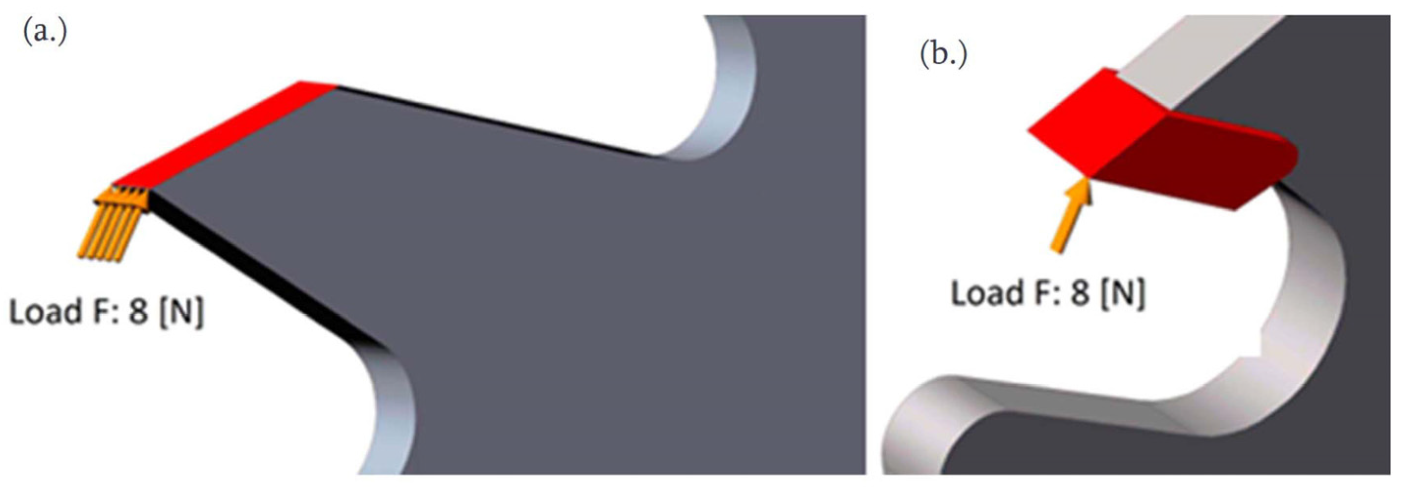
The cutting forces (
Figure 6,
Table 2) were placed at the highest points of the saw teeth because these parts of the teeth penetrate the workpiece first and are therefore the most stressed. The initial penetration of the highest point of the tooth into the workpiece is manifested by the area of a triangle, while this area is constantly increasing and changing, as a result of which the tooth penetrates deeper into the material. For tool steel discs, the entire edge of the saw tooth was loaded, because when placing the cutting forces at the highest points of the teeth, the hardware was not able to evaluate the number of mash grid points in the small area of the triangle and thus was not able to perform the simulation. The distribution of cutting forces on individual teeth is evident from
Figure 7 and
Figure 8.
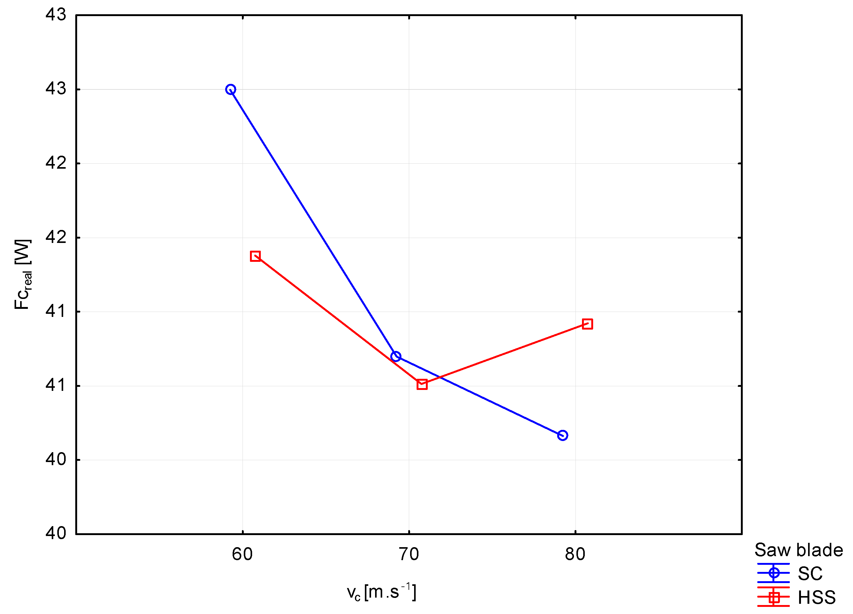
Figure 7 shows the course of the cutting force (
Fc) evaluated from the measured cutting power depending on the cutting speed (
vc) and type the saw blade used. In the case of a disc with SC plates, there is a significant decrease in cutting force with increasing cutting speed. With the HSS blade, similar to the SC, there is a visible decrease caused by a change in the cutting speed of 70 m·s
−1, but with a further increase in the cutting speed, the cutting force increases. The results of the stress analysis (
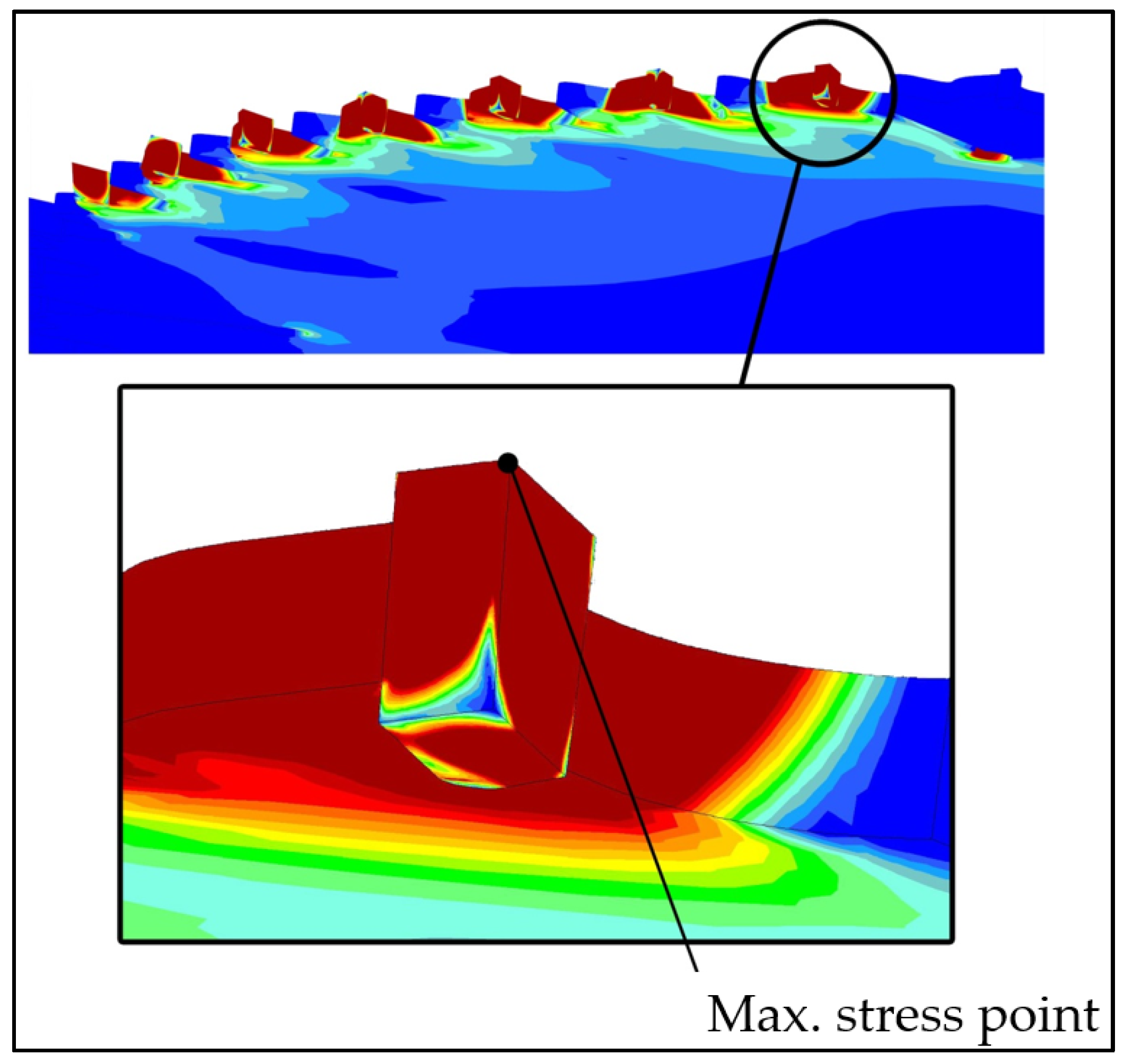
Figure 9,
Figure 10,
Figure 11,
Figure 12 and
Figure 13) show that the greatest stresses are concentrated at the highest point of the cutting edge of the saw teeth in the engagement. The cutting force at this location by saw blade HSS represented
Fc values from (3.43–7.79 N) per tooth and by SC (
Fc) values from (3.67–8.39N). The specific values of the forces on the teeth of the saw blade in engagement are shown in
Table 3 and
Table 4. The cutting force acted on the surface of the cutting edge uniformly; thus, it was able to simulate real stresses. The model of the tested teeth of the saw blade in the loaded state is shown in
Figure 7.
Number of teeth in engagement:
For a saw blade with SC blades with the number of teeth 54:
For HSS saw blade with fine teeth 56:
where:
D—diameter of the saw blade [mm],
By meshing the finite elements (
Figure 8) through the “Mash” function, the locales on the cutting part of the knife were thickened with greater precision, and smaller gaps were created between the individual elements created by meshing for the so-called subsequent mathematical calculation. The mesh elements consisted of linear hexagonal elements consisting of eight nodes and a parabolic tetrahedron, each containing 10 nodes. They consisted of a large number of vertices, where individual points could be connected and perform a more accurate stress analysis [
3,
19]. Moving away from this point, whether on the frontal, dorsal or lateral surface of the tooth, the stress values decreased significantly. At the same time, however, they appeared on both discs on the entire frontal and back part. This results from the fact that when the tooth enters the workpiece, its front part is stressed by tension, and conversely, the back part is stressed by pressure. Greater stresses were also recorded in the area of the clamping flanges, especially in the case of tool steel discs, which could be caused by the absorption of possible vibrations of the tool. The stresses in the area of the flanges were significantly lower in discs with SC plates. Tension concentrators for discs with SC were also dilatation grooves, which equalized the tension of the teeth in engagement. The simulation also shows that the body of the saw blades was stressed significantly less due to the maximum stresses. It is important to remember that compared to other parts of the saw blade, the stresses concentrated around the engaging teeth are still some of the greatest. Tension concentrators for discs with SC were also dilatation grooves, which equalized the tension of the teeth in engagement. The simulation also shows that the body of the saw blades was stressed significantly less due to the maximum stresses. It is important to remember that compared to other parts of the saw blade, the stresses concentrated around the engaging teeth are still some of the greatest.
In the narrow vicinity of these points, significantly lower stress values were found, ranging from 50 to 70 MPa. The maximum stress values for discs with SC can be justified by the fact that the program counted on a perfectly sharpened cutting tool, where the loading force was concentrated at the highest point of the tooth. In practice, this means that after a few shots of the disc into the workpiece, the cutting edges of the teeth would be slightly blunted, as a result of which the individual teeth in the shot would be loaded with significantly less tension than it turned out in the simulations. The simulation results also show that the stresses on the last tooth in engagement are greater than on the first tooth, with the first tooth taking the minimum chip thickness compared to the last tooth taking the maximum chip thickness. The simulation was carried out at the highest color gamut for 15 colors.
4. Conclusions
The results of the experiment show that the cutting conditions (cutting speed and feed speed) do not have a significant effect on the size of the cutting forces. The simulation results show that the highest stress values for both discs are concentrated on the tops of the cutting edges, which are the first to come into contact with the workpiece, while the maximum values are on the last tooth located in the engagement.
The theoretical and real stress values for HSS discs ranged from 14 to 22 MPa. Significantly larger differences were recorded for discs with SC, where the real values of the maximum stresses were around 14 MPa and the theoretical ones around 25 MPa. When cutting spruce with a disc with SC slices, the maximum values of the theoretical cutting forces were in the range of 76 to 94 N, and the maximum values of the measured cutting forces were in the range of 40 to 44 N. In operating conditions, this would mean that if the tool had perfectly sharp cutting edges (which it does not actually have), after a few shots of the disc into the workpiece, they would be slightly blunted, which would cause considerably less stress on the individual teeth in the shot than the simulation shows. The simulation results show that the highest stress values for both discs are concentrated on the tops of the cutting edges, which are the first to come into contact with the workpiece, while the maximum values are on the last tooth located in the engagement. The values of stresses on the cutting edges for discs loaded with theoretical cutting force were greater compared to discs loaded with real cutting force.


 ,
, 


