Abstract
Reforestation is performed after the final felling as an important and often law-mandated step to ensure that wood production is sustainable. In Sweden alone, over 400 millions seedlings are planted annually. This work is physically demanding and the quality is uneven. Therefore, automatic production systems are under research and development. A necessary effort in this endeavor is presented in this paper: the development and evaluation of a mission supervisor utilized to control the mission and behavior of a full-scale autonomous forest regeneration machine tested in realistic environments. The mission supervisor is implemented in the Robot Operating System framework using a finite state machine package called SMACH. A terrain machine built as a research platform with an added full-scale forwarder crane is used as a base machine. First, we describe the scenario in which planting is conducted, whereupon we develop the composite tasks required as states. A simplified simulator then enables an intermediate step before field experiments. The system is implemented and operated in real time on a full-scale machine. Results show that the developed SMACH mission supervisor can be used as a sound basis for an autonomous forest regeneration machine and the chosen communication solution between different systems works well. The simulations show good agreement with the experiments. The results also show that crane movements take 70% of the machine time, emphasizing the importance of limiting crane movement, improving the actuator movement speed and integrating the composite solutions. Further development with a holistic approach is required before the concept can reach the prototype level.
1. Introduction
Reforestation after final felling is an important part of the Swedish wood production cycle. Planting allows refined seedling material to be used with higher survival and growth rates compared to advance regeneration. Annually, more than 400 million seedlings are delivered to Swedish forests [1] and almost all of them are planted manually. The work is physically demanding and must be performed with good quality to ensure sufficient seedling survival and growth, which is required by law in Sweden [2]. Ground preparation, or scarification, is performed by different methods depending on the ground properties. Excavators with a special mounding tool are used in very stony terrain. More commonly used are disc trenchers or mounders pulled by forwarder machines on moderate and less difficult conditions, respectively. While the process is important for high seedling survival and growth, it has significant soil impacts. A disc trencher typically affects 50% of the area, while pulled mounders affect around 35% [3].
Mechanized planting devices are available as units mounted on excavator machines, such as the Bracke Forest P11.a and P12.a or the M-Planter from M-Planter Oy. These can carry numerous seedlings but the units are heavy and require the manual transfer of seedlings to the carousel on the device, which is time-consuming [4].
Historically, continuously and intermittently advancing planting machines have emerged. One early example of an intermittently advancing machine was the HIKO (or Hilleshög) planting machine [5,6], which had three planting arms that both scarified and planted. In the 1970s, the Nordic countries saw machines conducting forest regeneration continuously—the Swedish Silva Nova and the Finnish Serlachius machine, which planted with decent quality. They were abandoned some 30 years later due to a combination of reasons, such as high investment and running costs [7]. Today, however, continuously advancing planting machines are experiencing a renaissance as the Silva Nova has seen its successor in the Plantma X planting machine. It is built on a large forwarder and mainly uses disc trenching as a scarification method. Seedlings are planted at the back of the machine with the help of two hydraulically actuated planting arms. The planting arms are brought down onto the prepared ground, at which point a seedling is released. The machine is operated by one driver and a person at the back restocking seedlings. The planting quality is lower compared to manual planting, and it is most effective on heathland [8]. The planting quality is, however, addressed with emerging neural network technology to achieve adequate quality [9].
Other project initiatives are also in motion in Swedish silvicultural development. Södra Skog, a large forest industry group in Sweden, is currently working on a project with the goal to produce a functioning tree planting prototype during the summer of 2023 [10]. The main objective of this project is to reduce the footprint of the machine and actuators, while maintaining and, preferably, increasing the planting quality.
The work in this paper is part of the project AutoPlant, which was initiated in 2021, and field experiments were performed in 2022 [11]. The Autoplant project sought to make parts of the tree planting functions autonomous, leading to solutions for scarification, planting, crane control, seedling transfer, obstacle identification and base machine navigation. One major change and challenge in this project was the aim to reduce the scarified area to enable more precise planting with less ground disturbance. A plant ideally should have a humus edge clearance radius of 0.2 m [12], and with a plant density of 2500 plants/ha this gives a lower limit for the ground impact at 3%. The AutoPlant project aimed to approach this limit, which would decrease the ground impact by more than 90%. To target this aim, a new, innovative, high-precision scarification and planting device and seedling transfer system was developed by Bracke Forest as one part of the project. A major advantage of reducing the scarified area is that planting points can be chosen more decisively, i.e., a better decision basis from sensor data can increase the quality with which scarification and subsequent planting is conducted.
The top-level controller, the mission supervisor (or mission planner), which controlled the high-level actions of the autonomous AutoPlant system, was developed and evaluated during 2022. The objective of this paper is to present the development, implementation and evaluation of finite state machines (FSMs) for use as a mission supervisor in the AutoPlant project. The comprehensive AutoPlant system is built upon multiple subsystems, each designated for a specific function. The presented work primarily centers around the implementation and field experiment results of the mission supervisor and its role in harmonizing these subsystems to achieve the desired machine behavior. The explanations provided for the subsystems are intentionally brief and offer sufficient detail to provide the reader with a comprehension of their functions and contributions to the overarching controller’s architecture.
2. State Machines for Autonomous Control
Machines or robots designed to perform specific cycles, where one operation directly follows another, are straightforward to program, similar to creating a recipe for cooking. However, machines that require the ability to plan and execute complex tasks and handle a variety of situations without human intervention need to be autonomous. Autonomous machines, such as the AutoPlant project, can operate within uncertain and unstructured environments, managing unexpected events of both external and internal origin. The control logic of autonomous machines must be adaptable, capable of responding to conditions and choosing different paths of execution based on the situation or the outcomes of prior events. A simple program with predefined operations in a fixed order is insufficient to achieve the desired level of autonomy. This section provides the theoretical background and reasoning for selecting between two algorithmic principles to enable an autonomous machine for the AutoPlant concept.
Finite state machines (FSMs) are a common formalism in building complex systems, where the control logic is broken down into a finite set of states. The states typically represent some form of action being performed, while the transitions between states represent events taking place. FSMs are visually represented by state diagrams, where each state is a block and the transitions between states are indicated by arrows [13]. The transition condition is noted next to the transition arrow. A group of states that result in common entry and exit transitions can be grouped into superstates. Even superstates can further be combined into superstates. This allows complex machines to be represented at different levels. An FSM traditionally only has one active state at each instance. An extension is to use a concurrency superstate. The states or superstates within the concurrency operate in parallel, possibly independently of each other. In the open-source framework Robot Operating System (ROS), maintained by the nonprofit organization Open Robotics (Mountainview, CA, USA), the SMACH toolbox [14] aids in the design of FSMs in Python nodes.
In the research community, FSMs have been used as a basis in supervising architectures that work in a task-based manner. Fue et al. [15] used the ROS and SMACH to perform tasks with a cotton picking machine mechanically. Similar to the AutoPlant case, they too controlled an articulated machine with a hydrostatic drivetrain in-field and were quite successful in the outcome. SMACH was also used as a basis for tasks conducted by a robot butler [16], by the research group that first formalized the SMACH package and ROS integration, although there were issues with surrounding detection. As development continued in perception, researchers were able to improve these wheeled humanoids while still successfully using SMACH [17].
Behavior trees (BTs), which are another tool to model and implement complex behavior in robots, are based on a tree structure of interconnected tasks. Each task represents a specific behavior or action, and the robot’s behavior is determined by the combination and ordering of the tasks in the tree. BTs are considered flexible and can be easily modified or extended to add new behaviors. With their respective advantages and disadvantages, studies have found that BTs are more effective at representing complex behavior [18], while others have found that FSMs by comparison are more efficient and easier to manage and operate [19]. While BTs are interesting from an autonomous control perspective, FSMs are a more straightforward and well-known approach for the types of tasks that the AutoPlant project represents.
3. Materials and Methods
This section covers the machine used to implement the developed mission supervisor and explains the hardware and software components used to build the system.
3.1. Base Machine, Computers and Sensors
The presented system has been implemented on a research vehicle platform [20] specifically built to be used to conduct research on sites where future machines may operate. It targets research on autonomous navigation and control using on-board real-time systems that collect data during operation. The vehicle is equipped with proprioceptive and exteroceptive sensors, hydraulic pressure sensors and data collection systems that enable a full kinematic model representing the vehicle in real time. A GNSS Leica GPS-80 system with network-RTK (provided by Leica Geosystems, Sankt Gallen, Schweiz) enables the absolute vehicle position and heading to be tracked with high precision, to a few centimetres in translation and tenths of a degree in rotation. The main exteroceptive sensor used for perception is a ZED2 stereo camera from the manufacturer Stereolabs (San Francisco, CA, USA). The camera is pointed backwards from the driving direction since its main purpose is to allow the planting device to reach plantable ground.
The vehicle weight is approximately 10,000 kg, with a full-sized hydraulic crane mounted at the rear of the machine, enabling full-size tests of crane actuation in correct environments. The drivetrain is hydrostatic, with hydraulic motors on each wheel, powered by a hydraulic pump attached to a 129 kW diesel engine. Furthermore, the machine hardware includes a scarifying and tree planting device as an end-effector, and a seedling storage and seedling transmission system; see Figure 1.
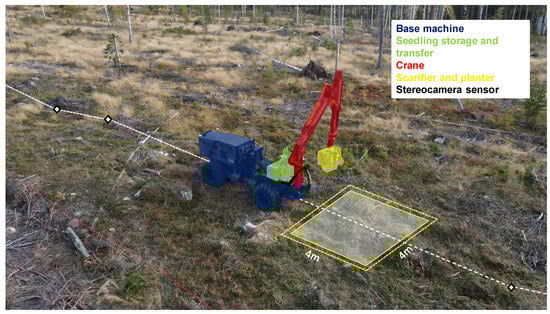
Figure 1.
The research platform including the AutoPlant machine, with the planter mounted on the crane and seedling system mounted at the back of the machine. Photograph courtesy of Gustav Sten.
As computing hardware, an NVIDIA Jetson AGX (provided by Nvidia Corp., Santa Clara, CA, USA) is used for cost-efficient graphics computing, in our case to run a neural network that detects and positions clearcut obstacles. The Jetson also connects through USB to the GNSS and reads positional data at 20 Hz. The low-level input/output system connection to sensors and actuation amplifiers consists of a data acquisition and control rack (provided by United Electronic Industries, Norwood, MA, USA), on which MATLAB/Simulink (2021b, Mathworks, Natick, MA, USA) runs in external mode. To increase the research flexibility, the ROS (Melodic distribution) runs on a high-performance laptop, connected to the machine control rack through a UDP network interface. This allows the laptop to quickly be moved from the machine and used to run in simulated environments to verify functions before running on the machine itself in real environments.
3.2. Planter Device
The planter system was developed and built by Bracke Forest (Bräcke, Sweden) for the AutoPlant project and has four parts: a seedling storage and transfer system, a scarifying and planting unit and an electrical cabinet for its control systems. The seedling storage and transfer system comprises a seedling tray holder that can hold one tray at a time. A custom-designed low-capacity robotic arm is used to transmit seedlings from the seedling tray and out to the crane end-effector. The crane end-effector consists of a device with three functions: scarification, planting and soil compaction. The end-effector can be positioned (by the crane) sufficiently close to the seedling transfer system such that one seedling at a time can be transferred to the end-effector. The scarifier uses a drilling-like motion with a hydraulic device to prepare the soil in a patch (cf. [21]) as a site preparation type and a center hole for a seedling to be placed. The planter drops a seedling into place and finally a hydraulically propelled puncher compacts the soil around the seedling. The control cabinet holds a Programmable Logic Controller (PLC) to control the seedling transfer robotic arm and the scarifying and planting program. The mission supervisor in this project can control these functions on a high level.
3.3. ROS
The Robot Operating System (ROS) (Melodic distribution [22]) is an open-source software framework that provides libraries and tools that help developers to build and manage complex robotic systems [23]. The ROS uses a publish–subscribe messaging system to facilitate communication between different software components, called nodes. Nodes can publish messages to a topic, and other nodes can subscribe to this topic to receive these messages.
3.3.1. Topics
Topics are named buses over which nodes exchange messages in a publish–subscribe pattern [23]. Topics are essentially a tool for nodes to communicate with one another, allowing them to share information and coordinate their activities. Each topic has a unique name, and the data being transmitted over a topic are defined by a message type.
3.3.2. Nodes
Nodes are individual software components that perform specific tasks, such as processing sensor data, controlling actuators or performing computations. Nodes communicate with one another by publishing and subscribing to topics, allowing them to coordinate their activities and exchange data. The nodes are typically written in Python or C++ [23], with versions mandated by the specific ROS distribution.
3.3.3. Action Calls
An action call is a type of message exchange between nodes that enables asynchronous, goal-oriented communication. It provides a means for one node to request a specific task to be performed by another node, with the expectation that the task may take some time to complete. An action call is typically initiated by a client node, which sends a goal message to a server node. This goal message specifies the desired outcome of the task to be performed. The server node receives the goal message, starts executing the task and can periodically send feedback to the client to report on its progress. Once the task is complete, the server node sends a result message back to the client, indicating whether the task was successful or not.
3.3.4. Building and Visualizing Digital Twins
A real-time updated digital twin of a robot is valuable for development, simulations, debugging and robot interfacing. In the ROS, the combination of the Unified Robot Description Format (URDF), RViz and tf packages provides a powerful toolset to build and visualize the digital twins of robots.
URDF is an XML-based file format to describe the structure, geometry, kinematics, dynamics and visual representation of a robot. The robot parts are represented as a tree of links connected by joints with optional sensors [24]. Links define the robot’s physical parts, including its appearance, dimensions and inertial properties, while joints describe the connections between links and the constraints on their relative motion. The appearance can be defined using primitive shapes or CAD meshes. Meshes can be in the format of STL, DAE or OBJ. Meshes exported from CAD systems can result in large files. To improve the performance in visualization, these files can be reduced in complexity using decimation in, for instance, Blender software versions 2.79 and up [25]. All links can have a collision shape, which typically should be a primitive shape or simple geometry to outline the link to improve the collision calculation performance.
The ROS package tf provides a means to track and manage coordinate frames over time in a distributed system, allowing for the translation and rotation of coordinates between different frames of reference [23]. The frame is specified as a text string. The standard frames base_link, odom and map are commonly used in ROS systems to represent the robot’s base frame, the odometry frame and the map frame, respectively. Transforms are sent using broadcasters and a receiver is called a listener. Certain message types, such as a point cloud message, include a frame identifier to specify which frame the data are represented in. This allows subscribers of the message to use a tf listener to perform transformations into any other frame of geometrical reference defined in the system.
RViz is a ROS 3D visualization tool that uses the URDF model to illustrate the state of the robot in real time [23]. Additional 2D or 3D information can be visualized in the tool in relation to the robot and the virtual world, such as LiDAR point clouds or camera imagery.
3.3.5. SMACH
The SMACH (State MACHine) package is a high-level library that allows developers to design and execute FSMs for complex robot behavior [26]. FSMs are commonly used in robotics to model and implement behavior that requires the robot to transition between different states in response to environmental stimuli.
SMACH provides a Python-based framework for the design of FSMs, with support for state machine introspection, visualization and execution. The package includes a set of pre-defined FSM components, such as states for the execution of actions, monitoring of topics and querying of services. SMACH can be used in combination with other ROS packages, such as the actionlib package for the execution of actions and the rospy package for communication with other nodes. The SMACH package further allows for the development of hierarchical FSMs (state machines within state machines). The SMACH introspection tool is called smach_viewer [27]. This view is autogenerated from code and the current state or states are indicated in real time.
3.3.6. Robotic Arm Motion Planning
The MoveIt™ version 1.0.11 ROS packages provide a tool chain to perform robotic motion planning [28]. MoveIt utilizes the joint_trajectory_controller of ros_control for robotic arm movement [29]. The MoveIt ROS packages utilizes kinematics, dynamics and control capabilities, along with advanced algorithms for collision avoidance, in order to effectively plan the movement of the robot arm. The software also supports integration with various types of sensors for perception, enhancing the robot arm’s ability to interact with its environment. The ability of MoveIt to provide collision-free paths is especially helpful for situations where the robot arm needs to navigate close to itself, such in the crane docking procedure of the AutoPlant concept.
The joint_trajectory_controller operates by taking in a trajectory and executing the movements by controlling the individual joints of the robot arm. This allows for control over both the path and final destination of the robot arm.
3.4. AutoPlant Scenario Description
The main task for the AutoPlant system was to autonomously conduct a full cycle of tree seedling planting in a real Nordic environment. The system needs a machine with navigation, seedling storage and transfer mechanisms, a scarification and planting tool, a planner to select the planting position and a mechanism to place the tool at the planting position.
The scenario assumptions can be explained as follows: 2D waypoints are output on a map of a clearcut beforehand and assumed to be traversable by the machine. The machine seedling storage is loaded manually with one seedling tray (a standard jackpot with 67 seedlings tray) and a robotic arm for seedling transfer to the planter, which is operated at each planting sequence. The scarification and planting tool is mounted as the crane’s end-effector, and the crane conducts the necessary movements for seedling refill and movements to reach the planting positions behind the machine.
At the time of sequence initiation, the machine is (manually) positioned on the clearcut area, pointing approximately towards the first waypoint. When placed in automatic mode, the machine performs the following.
- The machine moves 4 m towards the first waypoint.
- The crane moves out of the way of the plantable ground behind the machine while an onboard sensor collects data in a 4 m × 4 m area to use for decision support for planting positions; see Figure 1. The plant planning algorithm selects a suitable planting location free from detected obstacles. Meanwhile, the crane is positioned in such way that a seedling can be transferred into the planter unit (crane end-effector).
- The crane moves to a position above the selected planting position and then moves slowly until the ground is detected.
- Scarification and planting is performed.
- The result is documented.
- The crane is again positioned at the transfer position and receives another seedling.
- If the entire area is ultimately deemed planted (or otherwise impossible to plant), the machine is moved to the next staging area 4 m further down the predetermined path. When the entire clearcut area is considered to have been planted or otherwise evaluated, the machine reaches its finish point and the scenario ends.
In addition, the machine should not conduct seedling transfer if it is already carrying a seedling. It should also directly try a new planting position if the first attempt fails and the seedling is still available. This scenario can now be used to describe the mission and thus the sequential and parallel actions needed to succeed.
3.5. Required Client Actions
Based on the identified scenario of the AutoPlant project, a set of hardware systems was established along with functions or tasks. The functions were formulated as a set of actions that each subsystem must be able to perform, which are summarized in Table 1. All actions have return codes depending on the outcome of the requested action. These return codes are used by the mission supervisor to take proper execution paths.

Table 1.
The action and service commands used by the clients that are controlled directly by the mission supervisor; See also Figure 2.

Figure 2.
Control system overview.
3.6. Real-Time Digital Twin of the Machine and Surroundings
A URDF representation was built of the machine to allow an ROS digital twin of the machine. The visual parts were extracted as 3D meshes from the machine’s CAD model. The meshes were decimated to reduce the complexity and file size to a maximum of 5 MB for the largest parts. For the collision meshes of all machine parts, low-complexity models of equal outer dimensions were used. Blender version 3.0 was used for the decimation and to convert all mesh files into DAE format. The resulting digital twin is available in real time in RViz, as illustrated in Figure 3.
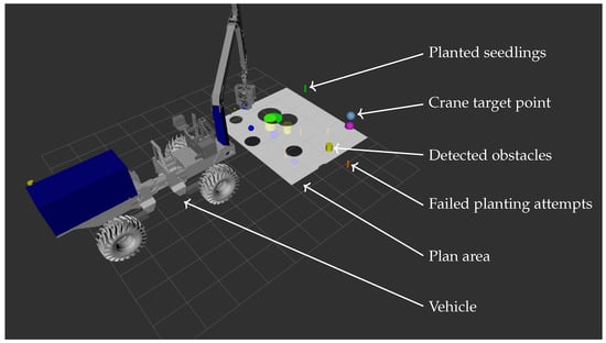
Figure 3.
Digital twin visual representation of the machine using RViz. Feedback from the plant planner, the obstacle detector and the crane sensors is also provided.
Timing is critical for the tf to give correct transformations in the tf system. Since the hardware clock of the host machine is used to set the time of ROS broadcasts, synchronization between hardware clocks needs to be ensured. Therefore, the main system laptop was set as the NTP server and the NVIDIA Jetson AGX unit was the NTP client.
3.7. The Mission Supervisor
The mission supervisor is implemented as an FSM with support for parallel state execution and runs in the ROS (distribution: Melodic) using Python code and the SMACH package. The different subsystems of the machine are handled using a set of action clients. Each client has various additional nodes and code to interface with the sensors and hardware. The mission supervisor is responsible for coordinating the machine operation by controlling each of the action clients. The clients in turn perform the commanded tasks and report back to the mission supervisor upon completion or failure. The control system hierarchy with the main communication paths is illustrated in Figure 2, with the mission supervisor at the top of the control chain. Most of the states in the mission supervisor correspond to the execution of a specific action from Table 1 by the corresponding subsystem. The transitions in the FSM depend on the reported outcomes from the clients. For instance, if the planter client reports failed planting, the execution takes a different path compared to the case in which the planting is successful. As previously described, the mission supervisor and all the clients operate in the ROS and are implemented in Python code. The mission supervisor FSM at the top level is shown in Figure 4.
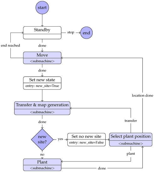
Figure 4.
The mission supervisor design, showing the top level. The submachines’ design materials are available in the Supplementary Materials, Figure S1.
3.7.1. State Classes and Client Interfaces
The states in SMACH are defined using a provided state class. To communicate with the clients, the mission supervisor uses ROS actions and service calls. Each client is responsible for multiple tasks and is involved in many states. To avoid the definition of the client communication in each state, the code to communicate with the clients is placed in a custom interface class. Each state keeps a reference to this interface class and uses it for communication with the clients. This also allows for an added functionality to ensure that an interface is not being called multiple times by different states. The interface class serves the same purpose as the built-in functionality of SMACH, called the proxy and action states. However, the use of a custom definition provides greater transparency and ability to collect application-specific code in the interface class.
The mission supervisor FSM was divided into superstates to enhance the readability of the autogenerated diagrams, i.e., hierarchical FSMs, which is an ability of SMACH.
3.7.2. System Status Variables
In addition, a set of variables was used to keep track of certain key system states. These system states comprise information about the system, in contrast to the mission supervisor states, which all represent some action to be performed. Keeping these properties as variables instead of additional states reduces the complexity of the FSM, at the cost of some transitional logic being “hidden” in the state diagram. The variables are as follows.
- has_seedling—a Boolean value to indicate whether the planting unit is holding a seedling or not.
- new_site—a Boolean value to indicate whether a new staging area has been reached.
3.8. Graphical User Interface (GUI)
The system has a user-interface-based design with a focus on the concept as a research tool. While the operator experience is an interesting topic, it was excluded from this project. The user interface is therefore technical and practical in its design, instead of being designed as a specific working product.
System start preparation involves a set of ROS launch files that need to be started on the different hardware units. The final launch file will start the main interface tools. The control interface is based on standard plugins from the ROS rtq tool [30]. From here, service calls to start and stop the machine can be sent to the mission supervisor and an error monitor collects errors from all ROS nodes in the system. The used rqt configuration is illustrated in Figure 5.
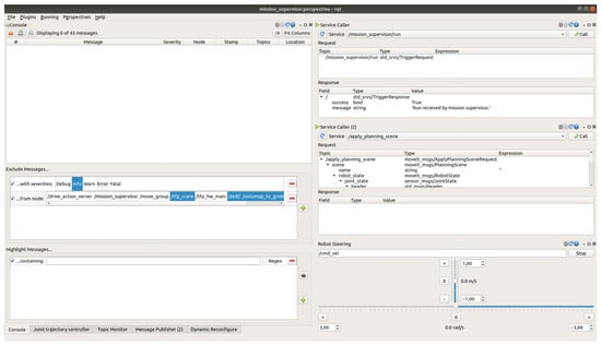
Figure 5.
Machine control GUI based on ROS RQT using standard plugins. Here, services and actions calls are called, and sequence starts and stops can be made.
The real-time digital twin representation of the machine in RViz adds a useful GUI component to the system. Visual feedback of the machine’s positional sensors, plant planner operation, planted seedlings and detected obstacles are presented in the RViz tool, illustrated by the screenshot in Figure 3. Markers illustrate different objects detected (e.g., a cylinder for a detected stump) and resulting planted seedlings and failed attempts, colorized differently depending on the outcome. The planted seedlings are kept in the digital environment, while the detected obstacles and the planting area are reset for each machine’s stop position.
The plant planner operation is illustrated by the planning map rendered as a surface that is updated at each planting attempt and obstacle detection.
Insights into the FSM of the mission supervisor are provided using the smach_viewer. This autogenerated view indicates the current state or states in real time; see Supplementary Materials Figure S2. This is useful information during debugging and for understanding the robot’s behavior.
3.9. Subsystem Clients
The subsequent section provides a summarized overview of the subsystems involved in the concept, as a comprehensive description of each subsystem is beyond the scope of this paper. Instead, the focus of this paper remains on the mission supervisor. To a large extent, the clients correlate to the hardware assemblies of the machine shown in Figure 1.
3.9.1. Drive
Drive is the client that controls the base machine, with the main responsibility for moving and steering the base machine. Low-level 4WD antispin and pendulum arm control are, however, managed by other systems. The default action of drive is to move a preset distance navigating along a predefined path. The path is the global plan for the machine, which is obtained by a planning tool before the sequence start. A dual-antenna GNSS with network-RTK correction provides positioning and heading so that the drive system can move the machine appropriately. The GNSS system was used as the single source of global positioning for the machine. Hence, the map and odom frames were placed in the same frame (no world frame was used). The tf tree was built from map and odom to gps. Therefore, gps, which was the GNSS receiver position on the machine, also had to be the root frame of the machine’s URDF. Drive broadcasts the transform from the map to the gps frame.
The current drive system implementation has no local planner to handle deviations in site conditions not previously covered by the global planner. However, from the mission supervisor’s point of view, the drive unit could implement a local plan when the action NEXT_POS is requested.
3.9.2. Plant Planner
The plant planner client is responsible for providing suitable locations in the crane operation area to place seedlings, also utilizing a map of the area that contains the locations of obstacles, previously planted seedlings and scarifications. Output from this client is a chosen terrain point for scarification, planting and soil compaction, which is achieved by the same device and in direct sequence.
An important part of the plant planner is the sublevel action client called the obstacle detector. This is called upon by the plant planner client when a new 4 m × 4 m site has been found and when the crane and machine are positioned correctly. Then, a snapshot is taken on the stage, where both image and depth data are saved. Utilizing a detector AI, obstacle types, sizes and positions are acquired and used as a decision basis for the plant planner client. Objects detected that are deemed obstacles to scarification and planting are output as non-plantable areas, whereby the plant planner bases its plant positioning decisions on the remaining area patches.
3.9.3. Planter
The planter client interfaces with the plant and scarification unit. The communication hardware interface has a digital parallel 3-bit duplex implementation based on a send and acknowledge structure. The actual planting unit holds a PLC with a program to control the planter and the seedling transfer system. It accepts commands such as “collect seedling”, “drop seedling into planting unit” and “scarify and plant”, encoded as integers. It returns success codes such as “completed”, “fail” or “planter jammed”. The planter client simply ensures the communication profile, converts the action calls into correct integer commands for the planter unit and collects the result codes.
3.9.4. Crane
To enable the features of MoveIt and the ros_control chain (see Section 3.3.6), a ros_control hardware interface node has been implemented. This hardware node also forwards the control signals from the drive and planter clients to the machine platform.
Additionally, a Python node was added that could process AutoPlant’s specific action calls from the mission supervisor and make requests to MoveIt, which used the trajectory controller to position the crane in the requested position or joint configuration.
This node also made the necessary transformations between the different reference frames of the requested crane tip positions and the MoveIt planning frame. MoveIt tends to use the robot root frame as the planning frame. Since the tf tree needs to be built from the top, the root frame of the robot needs to be the gps frame (as explained in Section 3.9.1). Since all crane planning was done in the planning frame, the movements had to be transformed into the gps frame.
The node also has access to the pressure of the crane’s inner boom cylinder, which is used to detect ground contact when placing the unit on the ground.
3.9.5. Plant Photo
One client called plant photo is responsible for quality assurance during the scenario sequence. This client is quite simple; when planting is finalized and the crane has started moving up and away from the scarified, planted and compacted planting position, the client is called and takes a photo of the planting point. This information is saved in a database along with the GNSS position.
3.10. Simulations
Simulators are a powerful tool in advanced system development that can decrease the time needed for actual system integration. Simulations can be used at different levels depending on the aim and purpose. The ROS offers efficient integration with the Gazebo simulator, which enables physical simulations and integration with ros_control, among many other possibilities. While Gazebo was successfully used in the beginning of the project, a custom simulator solution was found to be more suitable for our needs later on. The solution was based on a low-complexity simulator coded in Python, based on the measured joint properties of the machine. All joints of the machine had velocity interfaces; however, the hardware interface used a calibration procedure to obtain the output effort based on the requested velocity demand. The simulator used the calibration points in reverse to obtain the expected machine velocities from the output commands. The resulting joint position was obtained using
where is the joint position, is the joint position at the last time-step, is the time-step and v is the joint velocity. Acceleration limitations were ignored. The simulator was implemented as a Python node and used the same UDP interface as the actual machine, which made it possible to simulate the full chain including the ros_control hardware interface node.
The system overview in simulation mode is shown in Figure 6. To simulate the different subsystems, the following solutions were used.
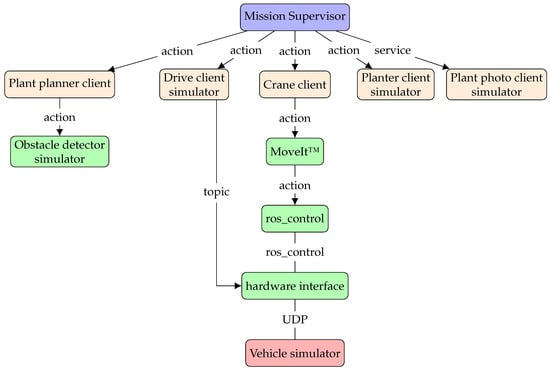
Figure 6.
Overview of the control system in simulation mode. Compare with the physical implementation depicted in Figure 2.
- Drive—The simulator took responsibility for updating the machine pose and position according to Equation (1).
- Plant planner—The obstacle detector had a simulator to randomize obstacles in the staging area. The plant planner itself was operational as usual.
- Crane—The chain extending to the UDP interface was the same as in real operation.
- Planter—The planter was replaced by timed delays that matched the actual processing times of the planting units. Failed attempts could be randomized with a customizable frequency.
- Plant photo—Replaced by a code to simply return completed.
3.11. Experiments
This section describes the integration experiments on the machine, the field experiments with the full concept and the computer simulations. The experiments aimed to show the capability to integrate all subsystems and the ability of the mission supervisor to successfully coordinate the systems in the desired behavior. Another target was to validate the simulations using experiments that could be replicated in the simulated environment.
3.11.1. Full Machine Integration
Planter unit integration was tested in a workshop to verify the communication protocol and mechanical, electrical and hydraulic interfaces. The planter unit’s performance was evaluated when mounted in a test bench and on the machine.
3.11.2. Machine Field Experiments
The complete AutoPlant assembly was also tested in a clearcut terrain on the outskirts of Bräcke, Sweden, 62.9130° N, 15.6330° E (WGS84). This experiment was conducted in order to integrate all the composite solutions and to test them with correct input data from exteroceptive and proprioceptive sensors. The tests were aligned with the scenario description in Section 3.4, although only one staging area was tested at a time and the drive state was run to and from one staging area. Figure 1 and Figure 7 shows the clearcut and machine during these tests. The mission supervisor was implemented on the machine platform with the drive client, crane client, planter interface and plant planner with the attached obstacle detector running.
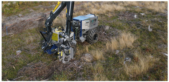
Figure 7.
The research platform in the role of the AutoPlant machine during field experiments. Photograph courtesy of Gustav Sten.
3.11.3. State Timing Field Experiments
The second field experiment aimed to evaluate the timings between different states, and to assess how and whether the machine and crane movements could be improved. The location was a flat grass area at Skogforsk Sävar station, 63.8944° N, 20.5489° E (WGS84), close to the town of Umeå in Sweden. Dummy obstacles were scattered on the ground with known positions and the planting device was emulated with a dummy (an ordinary grapple kept in a closed position); see Figure 8. The planter client was replaced by a node that simply returned a successful result after the same amount of time that the different operations took based on the test bench experiments of the planter unit.
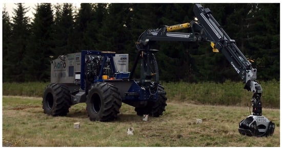
Figure 8.
The research platform in the role of the AutoPlant machine during the state timing field experiments. Photograph courtesy of Stina Johannesson.
3.11.4. State Timing Simulations
The simulations used the same settings for all system parts as the timing field experiments. The low-complexity simulator described in Section 3.10 was used. The obstacles were randomized in position and size and chosen in number to be similar to the dummy obstacles in the experiment. The simulator was allowed to run for a while to collect enough data to be able to find a situation with the same number of plantings per location as in the field experiments.
4. Results
This section presents the results from the physical experiments with the concept in the field, along with simulation comparisons.
4.1. System Design Verification
The output diagram from smach_viewer is given in the Supplementary Materials, Figure S2. Visual inspection confirmed that this diagram indeed corresponds to the design in Figure 4.
The autogenerated diagrams from the rqt_graph of the ROS system node communication and the ROS tf-tree are available in the Supplementary Materials, Figure S3 and Figure S4 respectively.
4.2. Full Integration Experiment
In the full integration experiment, the main focus was to ensure the communication between the different subsystems, both in the software and hardware. During the experiments, a total of three laptops (two for the ROS system) and one NVIDIA Jetson Xavier was online. A total of five terminal windows were active on the main laptop with separate launch files and Secure Shell (SSH) connections to the different systems. The reason for the many terminal windows was to be able to keep track of the errors and status of each of the different action nodes in use. In the integration tests, special care was taken to verify the planter unit’s communication. It was, however, noted that the planter unit was unable to reach full performance when mounted on the machine crane. The available hydraulic flow in the crane grapple functions was insufficient to supply the planter unit at full power. As a consequence, the unit operation speed and force were decreased. A work bench experiment timed the behavior of the planter unit when operating under optimal conditions. It was apparent that the planter unit design caused it to behave in a very predictable way in terms of time usage. The times for each operation are listed in Table 2.
Table 2.
Planter operation times with workbench hydraulic power supply.
4.3. State Timing and Simulation Comparison
Figure 9 shows the time spent in different states during a trial in the field experiment at Sävar. Each line represents one operational state. The sum of each state for the trial is presented in Figure 10. The details are listed in Table 3 and compared to a simulation with the same settings as the experiment. The crane motion planning calculation time is included in the crane time and is estimated to be <1 s per motion plan.
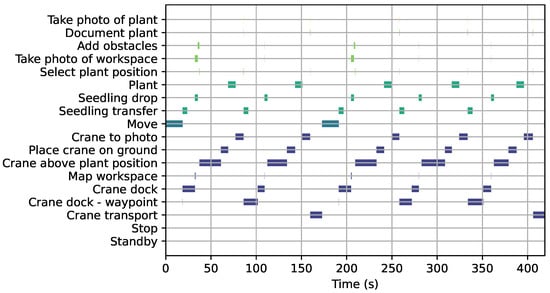
Figure 9.
State durations sorted by subsystem during the experiments at Sävar for two staging areas and a total of five planting attempts. Colors are coded according to which subcategory it resides within, see Figure 10. Bar length indicates the state duration.
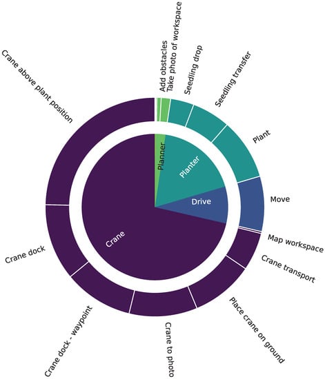
Figure 10.
Relative time usage of the subsystems and their operations during the experimental durations in Figure 9. The diagram total is 450.5 s; labels for durations less than 1 s are not printed. Total duration of the analysis is 419.0 s and the simultaneous operations therefore save 7.5% time.
Table 3.
Simulation and experiment total time comparison for two machine movements and five planting attempts (without retries). States with total time shorter than 1 s are excluded. Note that the planter was simulated in the experiment as well, hence the exact figures.
The difference between the simulation and experiment for the planter was negligible due to the fact that both cases were simulated. During the timing experiments, the planter was emulated with timings from the bench experiment, as explained in Section 3.11.3.
5. Discussion
This section discusses the outcomes of the simulations and field experiments, as well as the implementation and usage of the ROS SMACH as a means of creating an FSM.
5.1. Discussion of Results
The problem of insufficient hydraulic power for the planter unit could be solved by dedicated hydraulic hoses of sufficient dimensions and is not considered a limitation of the concept. In total, the entire system’s energy consumption did not exceed the available amount, which led us to conclude that the machine size of 10 tonnes is sufficient for this application. Furthermore, at this machine size, it is plausible that at least half of a metal frame of containerized seedlings (approximately 2000 seedlings) can fit within the machine at each loading cycle. Bracke Forest’s implemented solution for seedling transfer works well in transferring seedlings from the tray to the planting device, and while a technical solution to move seedling trays around in the storage unit is not implemented on our machine, we see this as a surmountable obstacle.
The most important function of the planting machine is to conduct planting satisfactorily. The mission supervisor implemented and described in this paper was successfully used to this end. However, the hardware solutions for the scarification and planting functions (and the power to these functions) are a work in progress and were not at the proper state to be evaluated with long-term tests at the time of the field tests conducted for this study. The qualitative impressions that we gained from the field tests were, however, positive as some points were successfully patch-scarified and planted.
From the timing studies, the crane movements were clearly the most time-consuming part of the system. A major improvement would be to carry more seedlings in the planter unit head, thus placing a demand on the seedling transfer function to be able to transfer more than one seedling to the planting unit. The crane was also not entirely suitable for the task at hand; a smaller and faster crane that still is able to apply ground pressure is probably needed. Indeed, faster and lighter robotic arms are often used for the ROS MoveIt package. The ideal end-effector carrying capacity would be as many seedlings as can be placed in one staging area. A further improvement would be to perform the seedling transfer while the machine is moving to the next staging area. Of note is that in order to move the crane to take a photo of the seedling and to locate the ground, the same amount of time is required as to position the entire machine. Improvements to the crane speed can be achieved, as the crane motion control had not reached its full potential at the time of the experiments. Nonetheless, it is clear that increasing the crane speed, possibly by using a smaller crane or a bespoke one, and using smaller position steps are important aspects to reduce the machine’s time consumption.
One common problem during the integration field experiments was the narrow tolerances set in the ROS MoveIt package for manipulator control. These were not optimized for a hydraulic forestry crane with rather noisy sensors, and they caused the task execution to fail in some movements. While the problem was solved for the second field experiment (at Sävar), this demonstrated the need for suitable failure procedures, as discussed as a very important feature by the original SMACH inventors [16]. The proposed mission supervisor should therefore be extended with more failure recovery features.
While the mission supervisor was implemented to allow parallel task execution, the actual benefit was quite low. However, if seedling transfer could take place during machine movement, this capability could offer greater potential. The rather long drop part of the planter during seedling transfer is due to the robotic arm making a final movement above the planter head after docking. This process could easily be executed during crane docking instead and only the actual drop should be left for after docking. This would, in practice, almost eliminate the drop time from the overall machine time. It is also notable that the calculation parts of the system, such as object detection and plant planning, require negligible time compared to the physical movements.
5.2. Simulations
The use of simulations has been a central tool during the development of the mission supervisor and most of the subsystems in the AutoPlant concept. Further reductions in machine time could be achieved by incorporating a development stage that utilizes the actual computational hardware and a comparable network setup. Moreover, virtualization software could provide supplementary opportunities by enabling the emulation of additional hardware systems.
The presented low-complexity simulator shows impressive agreement with the real machine, although with underestimated drive movements caused by the lack of acceleration limitations in the simulator. The strong correlation between the experimental data and simulation results enables the use of the simulator to examine the impact of various choices in well-controlled environments. This allows for the virtual exploration of machine, crane and algorithm designs without the need to fabricate and assemble all variants. This is particularly beneficial in the context of operating costly, heavy machinery and in scenarios where maintaining experimental consistency proves challenging, thereby ensuring repeatable trials.
5.3. Abstraction Level
The tasks executed by the mission supervisor operate at a high level of abstraction. For example, the directive to move the crane to the docking position could have been decomposed into a universal capability within the crane client to arrange the crane in the requested joint configuration. Subsequently, the mission supervisor could request various joint configurations and velocity adjustments. One benefit of the chosen methodology is that most of the clients can be optimized in their execution of the tasks independently of the mission supervisor. Moreover, all specifications related to client operations can be consolidated and managed within the client package. However, this approach does have a disadvantage: the introduction of a new client feature necessitate updates to both the mission supervisor and the client, as well as the intermediate communication interface.
5.4. ROS as Development Tool
The ROS and many of its packages have been used as basis for machine control during this project. It is advantageous to use the ROS for this type of application since many of the packages exist in open-source form and can be quite easily implemented and adjusted to fit a specific robot setup. The disadvantage with this modularized method of building a robot is that some modules are not suited perfectly to the actual hardware setup or the environment in which the robot works and can be either too general or too specific. To take one example, the crane package MoveIt was used for trajectory planning and execution in our hydraulically actuated crane. While the MoveIt package seems adaptable to almost any robot arm setup, the default settings, examples and documentation tend to assume a standard electrically actuated arm. This could pose a significant challenge when implementing a 2000 kg crane with a reach of 10 m controlled by non-linear hydraulics with noisy position feedback and complex dynamics.
The distributed nature of the ROS, with the ability to distribute execution to several hardware systems and use different nodes, offers potential for modular design. For a rather large and complex system, such as the one presented, it also presents some challenges in terms of enabling all nodes and hardware to work at the same time. During the experiments, a total of three laptops (two for the ROS system and one NVIDIA Jetson Xavier) were online. Having many hardware components’ nodes being active simultaneously to keep track of the errors and status can be problematic at times when trying to debug a certain error. Even seemingly insignificant issues, such as two hardware clocks not being synchronized, can cause problems that are difficult to decipher. Another problem with serious consequences is the starting order of the nodes. At the simulation time, the nodes may start in one set of order that works well but, in the real system, the starting order could be different, which can cause a system failure or unusual behavior.
The ROS hardware control operates on separate hardware from the I/O computer, contributing to the delay in the control loop. The C++ implementation of ros_control is efficient (faster than a previously used Python ROS interface on the machine), and no issues related to delays in communication were observed in the crane and machine control. However, this system’s resilience to delay is largely due to the slow-changing nature of sensor feedback for the position and angle from the crane and machine. If there is a need for a control loop based on hydraulic pressure feedback for crane operation, the necessary time-step would need to correlate with the fluid’s bulk modulus of elasticity. This would require time-steps in the order of milliseconds, matching or exceeding the current time delay between the ROS and the hardware I/O. In such cases where the feedback of hydraulic pressure or accelerations is used, additional testing would be required to evaluate the effect of delays.
The SMACH package in the ROS enables the user to code the states with Python. The interface itself is code-based, while the outcome can be visualized. This is quite different compared to, e.g., MATLAB/Simulink, where a GUI is used to build the states and transitions as blocks and arrows, rendering the outcome in a graphically sensible way. Moreover, Schleger et al. [31] conclude that a user-friendly GUI is needed and is lacking in SMACH. Nevertheless, the outcome of SMACH enables superstates and other important features, which still makes the usage valid for almost any case. Importantly, engineers involved in the mission supervisor’s development and the development of its composite functions can work directly in the code and use storage, tracking and collaborative functions from external platforms, such as GitHub, Bitbucket or Azure DevOps. However, FSMs are, by nature, graphical, and diagram-drawing software is needed as a supplement for the effective design of complex FSMs. Another realization is the advantage of using substate machines to organize the states into more manageable blocks. This allows the functionality to be visualized in limited space, and by keeping the structure in the SMACH implementation, the generated diagrams are more readable and easier to compare to the drawings.
ROS 1, which is the framework that we have used for development, is not a real-time operating system. In fact, peripheral workspaces are built on the machine directly in user-friendly environments, instead of deploying binary packages. This could be an important disadvantage when the robot is deployed as a real product, as some functionalities may require that the clock cycles and the work performed during the cycle are stable. Nevertheless, as productization approaches, ROS 2 and the ROS Tooling Working Group’s tools [32] could be used to build minimal workspaces on edge machines but still maintain the advantage of easy code changes. ROS 2 also includes the implementation of a quality of service system that allows policy rules to be stated for node communication to ensure reliability, durability, a correct lifespan, etc.
5.5. Future Work
During this project, the aim was to obtain conceptual results and to show and evaluate the potential of the different subsystems. The used vehicle is a means for research and development and not a planting machine prototype. Further development is required before the concept can reach the prototype level. We suggest a holistic optimization process to integrate these developed composite solutions with more suitable components for the machine, crane, power unit, drivetrain, electronics, etc.
From the mission supervisor perspective, additional control logic is needed to handle various subsystem errors and other deviations that have not been discovered in our limited field trials, along with more user-friendly interfaces. Proper navigation control is also still lacking in terms of handling events not searched for, such as suddenly emerging obstacles, sharp turns and people or animals in the work area. The machine system will need to incorporate more functionalities, such as refueling, the reloading of seedling trays, handling navigation obstacles or recovering from certain errors (cf. [16]), to increase the technology readiness level. The presented FSM concept is a good foundation for the addition of such functions. In recent years, significant updates have been made to the packages and software within the ROS 2 environment that have been essential to this project. Given these enhancements, especially in terms of productization and communication performance, it would be beneficial to consider further work within the ROS 2 framework.
6. Conclusions
The objective of this paper was to present the implementation process, test outcomes and evaluation of an FSM as a control system for an autonomous forest regeneration machine for Nordic conditions. The machine’s task comprised a full tree planting cycle in the field, which was completed successfully. The concept as such still lack obvious functions, such as people detection and safety. Improvements are needed to the design, especially to increase the crane speed and to increase the head’s seedling-carrying capacity. However, the presented mission supervisor based on FSMs with parallel execution capabilities seems to provide sufficient capability to coordinate the operation of an autonomous reforestation machine. The modular approach including subsystems and a mission supervisor as a coordinator allows subsystems to be extended or added to offer more functionalities. The FSM can be adjusted to accommodate new execution behavior based on the new subsystems.
The utilization of simulations has been instrumental in significantly reducing the development time required on the physical machinery. Despite new challenges that have surfaced during the process of full integration, the agreement between the experimental results and simulations is promising. This correspondence implies that simulations could serve as a reliable platform in evaluating and comparing the performance of different algorithms and operation strategies.
Supplementary Materials
The following supporting information can be downloaded at: https://www.mdpi.com/article/10.3390/f14071340/s1, Figure S1: Submachine design material; Figure S2: SMACH diagram; Figure S3: Node graph communication diagram from rqt_graph; Figure S4: The tf tree from rqt plugin TF tree.
Author Contributions
Conceptualization, M.R. and H.L.; methodology, M.R. and H.L.; software, M.R.; validation, M.R. and H.L.; writing, M.R. and H.L. All authors have read and agreed to the published version of the manuscript.
Funding
This research was funded by Sweden’s innovation agency, Vinnova, grant number 2020-04202 (AutoPlant).
Data Availability Statement
The data presented in this study are available on request from the corresponding author.
Acknowledgments
First, we would like to acknowledge our partners in the AutoPlant project, as well as all contributing companies. We gratefully acknowledge project leader Linnea Hansson for her leadership, expertise and direct involvement with the project while leading multiple organizations towards a shared goal in AutoPlant.
Conflicts of Interest
The authors declare no conflict of interest.
Abbreviations
The following abbreviations are used in this manuscript:
| BT | Behavior Tree |
| CAD | Computer-Aided Design |
| FSM | Finite State Machine |
| GNSS | Global Navigation Satellite System |
| GUI | Graphical User Interface |
| LiDAR | Light Detection and Ranging |
| NTP | Network Time Protocol |
| PLC | Programmable Logic Controller |
| ROS | Robot Operating System |
| RTK | Real-Time Kinematic |
| SSH | Secure Shell |
| UDP | User Datagram Protocol |
| URDF | Unified Robot Description Format |
| USB | Universal Serial Bus |
| WGS84 | World Geodetic System 1984 |
| XML | eXtensible Markup Language |
References
- Levererade skogsplantor 2020. In Serie JO—Jordbruk, Skogsbruk Och Fiske; Skogsstyrelsen: Jönköping, Sweden, 2021; Number JO0313 SM2001; ISSN 1654-4021.
- Skogsvårdslag (1979:429). Ministry of Rural Affairs and Infrastructure, Swedish Government. Available online: https://www.riksdagen.se/sv/dokument-lagar/dokument/svensk-forfattningssamling/skogsvardslag-1979429_sfs-1979-429 (accessed on 10 February 2023).
- Lundmark, J.E. Influence of soil conditions on long-term productive capacity of the sites [In Swedish with English summary]. In Site-Adapted Scarification—A Theoretical Analysis of Some Scarification Principles; The Forest Operations Institute of Sweden: Stockholm, Sweden, 1986; Nr 3; ISSN 0346-6671. [Google Scholar]
- Ersson, B.; Bergsten, U.; Lindroos, O. Reloading mechanized tree planting devices faster using a seedling tray carousel. Silva Fenn. 2014, 48, 1064. [Google Scholar] [CrossRef]
- Myhrman, D.; Zylberstein, M. Fem Planteringsmaskiner; Forskningsstiftelsen Skogsarbeten: Stockholm, Sweden, 1983; Volume 18. [Google Scholar]
- Sundblad, L.G.; Hannerz, M.; Manner, J.; Ersson, B.T. Tidigare, Nuvarande Och Framtida Planteringsmaskiner; Skogforsk: Uppsala, Sweden, 2023; Volume 1149. [Google Scholar]
- Nilsson, U.; Luoranen, J.; Kolström, T.; Örlander, G.; Puttonen, P. Reforestation with planting in northern Europe. Scand. J. For. Res. 2010, 25, 283–294. [Google Scholar] [CrossRef]
- Ersson, B.T. Maskinell Plantering—Analys av Planteringsmaskinen PlantmaX Potential Inom Privatskogsbruket; Number 2022:01 in SLU Skogsmästarskolans Rapportserie; Sveriges Lantbruksuniversitet, Skogsmästarskolan: Skinnskatteberg, Sweden, 2022. [Google Scholar]
- Johansson, J.; Semberg, T. Mekanisk Planteringsmaskin Lär Sig “se” var Plantan Ska Sättas; Skogforsk: Uppsala, Sweden, 2022; Volume 67. [Google Scholar]
- Södra Skogsägarna. Första Steget Mot en Självgående Planteringsmaskin. 2022. Available online: https://www.sodra.com/sv/se/skog-medlem/aktuellt/sodrakontakt/nyhetsartiklar/2022/nummer-4/forsta-steget-mot-en-sjalvgaende-planteringsmaskin/ (accessed on 27 April 2023).
- Skogforsk. Autonom Skogsföryngring Testad. 2022. Available online: https://www.skogforsk.se/nyheter/2022/autonom-skogsforyngringsmaskin-testad/ (accessed on 28 April 2023).
- Örlander, G.; Nordlander, G. Skärmar, Markberedning Och Andra Skogsskötselåtgärder-kan de Minska Snytbaggeskadorna. K. Skogs-och Lantbruksakademiens Tidskr. 1998, 137, 59–69. [Google Scholar]
- Harel, D. Statecharts: A visual formalism for complex systems. Sci. Comput. Program. 1987, 8, 231–274. [Google Scholar] [CrossRef]
- Bohren, J.; Cousins, S. The SMACH High-Level Executive [ROS News]. IEEE Robot. Autom. Mag. 2010, 17, 18–20. [Google Scholar] [CrossRef]
- Fue, K.; Porter, W.; Barnes, E.; Li, C.; Rains, G. Center-Articulated Hydrostatic Cotton Harvesting Rover Using Visual-Servoing Control and a Finite State Machine. Electronics 2020, 9, 1226. [Google Scholar] [CrossRef]
- Bohren, J.; Rusu, R.B.; Jones, E.G.; Marder-Eppstein, E.; Pantofaru, C.; Wise, M.; Mösenlechner, L.; Meeussen, W.; Holzer, S. Towards autonomous robotic butlers: Lessons learned with the PR2. In Proceedings of the 2011 IEEE International Conference on Robotics and Automation, Shanghai, China, 9–13 May 2011; pp. 5568–5575. [Google Scholar] [CrossRef]
- Lee, M.; Heo, Y.; Park, J.; Yang, H.D.; Jang, H.D.; Benz, P.; Park, H.; Kweon, I.S.; Oh, J.H. Fast perception, planning, and execution for a robotic butler: Wheeled humanoid m-hubo. In Proceedings of the 2019 IEEE/RSJ International Conference on Intelligent Robots and Systems (IROS), Venetian Macao, Macau, 4–8 November 2019; pp. 5444–5451. [Google Scholar] [CrossRef]
- Colledanchise, M.; Ögren, P. Behavior Trees in Robotics and AI: An Introduction; CRC Press: Boca Raton, FL, USA, 2018. [Google Scholar] [CrossRef]
- Colledanchise, M. Behavior Trees in Robotics. Ph.D. Thesis, KTH Royal Institute of Technology, Stockholm, Sweden, 2017. [Google Scholar]
- Lideskog, H.; Karlberg, M.; Bergsten, U. Development of a research vehicle platform to improve productivity and value-extraction in forestry. Procedia CIRP 2015, 38, 68–73. [Google Scholar] [CrossRef]
- Löf, M.; Dey, D.C.; Navarro, R.M.; Jacobs, D.F. Mechanical site preparation for forest restoration. New For. 2012, 43, 825–848. [Google Scholar] [CrossRef]
- Robot Operating System (ROS) Melodic Main Webpage. Available online: http://wiki.ros.org/melodic (accessed on 29 May 2023).
- Quigley, M.; Conley, K.; Gerkey, B.; Faust, J.; Foote, T.; Leibs, J.; Wheeler, R.; Ng, A.Y. ROS: An open-source Robot Operating System. ICRA Workshop Open Source Softw. 2009, 3, 5. [Google Scholar]
- Unified Robot Description Format (URDF). Available online: http://wiki.ros.org/urdf (accessed on 10 February 2023).
- Blender—A 3D Modelling and Rendering Package. Available online: http://www.blender.org (accessed on 30 May 2023).
- Beyer, J.; Chung, J.J.; Kuffner, J. SMACH: A modular framework for building complex behaviors in ROS. In Proceedings of the IEEE International Conference on Robotics and Automation (ICRA), Anchorage, AK, USA, 3–7 May 2010; pp. 1848–1855. [Google Scholar] [CrossRef]
- smach_viewer: Graphical User Interface for SMACH State Machines. Available online: http://wiki.ros.org/smach_viewer (accessed on 10 February 2023).
- Coleman, D.; Suca, I.; Chitta, S.; Correll, N. Reducing the Barrier to Entry of Complex Robotic Software: A MoveIt! Case Study. J. Softw. Eng. Robot. 2014, 5, 3–16. [Google Scholar] [CrossRef]
- Chitta, S.; Marder-Eppstein, E.; Meeussen, W.; Pradeep, V.; Rodríguez Tsouroukdissian, A.; Bohren, J.; Coleman, D.; Magyar, B.; Raiola, G.; Lüdtke, M.; et al. ros_control: A generic and simple control framework for ROS. J. Open Source Softw. 2017, 2, 456. [Google Scholar] [CrossRef]
- RQT: ROS GUI Tool. Available online: http://wiki.ros.org/rqt (accessed on 10 February 2023).
- Schlegel, K.; Neubert, P.; Protzel, P. Building a navigation system for a shopping assistant robot from off-the-shelf components. In Proceedings of the Towards Autonomous Robotic Systems: 21st Annual Conference, TAROS 2020, Nottingham, UK, 16 September 2020; Springer Nature: Cham, Switzerland, 2020; pp. 103–115. [Google Scholar] [CrossRef]
- ROS 2 Tooling Working Group Github. Available online: http://ros-tooling.github.io (accessed on 29 May 2023).


Disclaimer/Publisher’s Note: The statements, opinions and data contained in all publications are solely those of the individual author(s) and contributor(s) and not of MDPI and/or the editor(s). MDPI and/or the editor(s) disclaim responsibility for any injury to people or property resulting from any ideas, methods, instructions or products referred to in the content. |
© 2023 by the authors. Licensee MDPI, Basel, Switzerland. This article is an open access article distributed under the terms and conditions of the Creative Commons Attribution (CC BY) license (https://creativecommons.org/licenses/by/4.0/).