Abstract
The seismic performance of a light wood frame structure is determined by sheathing-to-framing joints. In order to encourage the use of more sustainable materials in structures, the spruce-pine-fir (SPF) panel and the bamboo scrimber (BS) panel were considered as sheathing materials. Monotonic and cyclic tests were conducted on the joints with different parameters to obtain their mechanical properties. Moreover, the design value of the bearing capacity of sheathing-to-framing joints was calculated and compared in accordance with Chinese code (GB50005) and European code (Eurocode 5). Based on the test results and the design codes, the reliability index of the design value of the bearing capacity of joints was calculated using the first-order reliability method (FORM). Results demonstrate that the joints have high bearing capacity and stiffness at initial loading stage when the loading direction is perpendicular to the framing grain. BS panels make better use of the bending strength of fasteners than SPF panels. The screwed joints have lower strength and stiffness degradation than nailed joints, but the nailed joints show better ductile and dissipation than screwed joints. In addition, the reliability indexes of design bearing capacity calculated by the Chinese code of joints under monotonic load are conservative, but those of joints under cyclic load are unconservative. Therefore, in order to ensure the safety and economy of design, a modification factor for the GB50005 design method of joints is proposed to meet the target reliability index.
1. Introduction
With the development of the forestry industry, wood and bamboo as renewable and environmentally friendly materials are widely used in construction [1,2,3]. Light wood frame structures are frequently used around the world due to their relatively good seismic and ductile behavior [4,5]. Shear walls and horizontal diaphragms in these structures, which are typically composed of framing, sheathing panels, and fasteners, are considered to resist lateral loads during winds and earthquakes [6]. Extensive experimental programs and numerical research studies have been conducted to study the lateral performance of shear walls and horizontal diaphragms [7,8]. The dominant failure mode of the shear wall and horizontal diaphragm with different details was the failure of sheathing-to-framing joints [9,10]. In particular, studies related to specimens with oriented strand board (OSB) panels suggested that weak links between the framing and the sheathing panel result in lower utilization of the material’s strength [11,12]. Accordingly, the sheathing-to-framing joints have a significant influence on the load-carrying capacity and overall structural performance of light wood frame structures [13,14]. Moreover, the finite element analysis model of shear walls and horizontal diaphragms has been established according to the load–displacement relationships of sheathing-to-framing joints obtained from tests [15,16,17]. It is therefore essential to investigate the mechanical properties of sheathing-to-framing joints under monotonic and cyclic loading tests.
Investigations on sheathing-to-framing joints have mainly focused on joints with traditional sheathing materials, such as OSB, plywood boards, and gypsum fiber boards [11,12,18,19]. Robert Jockwer et al. investigated the load-carrying capacity of connections with metal dowel-type fasteners [20]. The results of which showed that different design modes and reliability requirements should be considered for different failure modes. In order to improve the mechanical properties of sheathing-to-framing joints, investigations have considered the use of high-strength materials for joints sheathing panels [21,22,23]. Wei Zheng et al. investigated the behavior of screwed sheathing-to-framing joints with plybamboo [24]. The aforementioned research showed that high-strength sheathing material can significantly improve the behavior of sheathing-to-framing joints. Bamboo scrimber (BS) is an innovative bamboo fiber-based material that has significant application potential for outdoor flooring and building materials [25]. Moreover, spruce-pine-fir (SPF) has been used by humanity for thousands of years because this natural fiber material has a high ratio of strength to weight, low production cost, and ease of manufacturing [26]. However, BS and SPF panels have been used less in light wood frame structures.
Therefore, in order to encourage the use of more sustainable materials in light wood frame structures and promote the development of related industries, the mechanical properties of sheathing-to-framing joints with SPF and BS panels are investigated under monotonic and cyclic loads. A total of 104 specimens are tested (80 monotonic, 24 cyclic). Different specimen configurations are considered, taking into account the possibility of variable loading directions (loading direction perpendicular to framing grain or loading direction parallel to framing grain), variable sheathing materials (10 mm SPF panel, 10 mm BS panel), and variable fastener types (smooth nails, screw). The ultimate bearing capacity, stiffness, strength and stiffness degradation, and equivalent viscous damping of sheathing-to-framing joints are obtained and discussed. Furthermore, the design value of bearing capacity of the joints is calculated and compared in accordance with Chinese code (GB50005-2017) [27] and European code (Eurocode 5) [28]. In order to examine the reliability index of different design methods, the reliability analysis is carried out by the first-order second-moment reliability method. Based on test and reliability analysis results, the application and design suggestions of the joints with different characteristics in light wood frame structures are discussed. This study offers theoretical and experimental supports for the application of PSB panels and SPF panels in light wood frame structures.
2. Materials and Methods
2.1. Material Specifications and Specimen Design
Chinese IIIc spruce-pine-fir (SPF) 38 × 89 mm lumbers were used as framing members. Bamboo scrimber (BS) panels and spruce-pine-fir (SPF) panels, in thicknesses 10 mm, with a planar dimension of 100 × 300 mm, were used as sheathing panels. The average measured density of SPF was 420 kg/m3 and of BS was 1100 kg/m3. The equilibrium moisture content of SPF ranged between 11% and 13%, and the equilibrium moisture content of BS ranged between 6% and 8% [27,29]. The moisture contents of SPF and BS in this study were 12% and 6%, respectively. As the codes do not specify the embedment strength of BS panels, the embedment strength of BS panels was 90.89 N/mm2, which were obtained from tests according to ISO 10984 [30]. Smooth nails and screws, 2.5 mm in effective diameter, 50 mm in length, were used as sheathing-to-framing fasteners. The materials of smooth nails and screws were low carbon steel and medium carbon steel, respectively. The bending yield strength of nails, measured according to ASTM F1575-03 [31], was 836.91 N/mm2 and of screws was 1857.17 N/mm2. The tests of sheathing-to-framing joints were manufactured with a total number of 104 tests (Table 1). The details of the sheathing-to-framing joints are shown in Figure 1. There was a predrilled hole in every joint at location on the fastener. The diameter of predrilled holes was 2.5 mm.

Table 1.
Parameters of the test specimens.
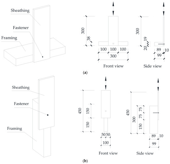
Figure 1.
Dimensions and manufacturing details of the test specimens: (a) Perpendicular joints; (b) Parallel joints. (Unit: mm).
2.2. Experimental Testing Procedure
The steel jigs used for sheathing-to-framing joints are shown in Figure 2. Monotonic lateral tests of joints were performed under deformation control with a loading rate of 2.54 mm/min for nail joints in accordance with the ASTM D1761 [32]. In cyclic test, the loading history was in accordance with the ISO 16670 [33]. The amplitude of the cycles was defined as a function of the ultimate displacement, obtained in the corresponding monotonic test. In order to ensure sufficient vertical displacement in cyclic tests, a rigid pad with the same size as the framing member was set at the bottom of the perpendicular joints.
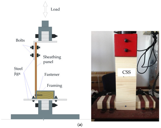
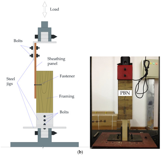
Figure 2.
Experimental setups of the joints: (a) Perpendicular joints; (b) Parallel joints.
2.3. Mechanical Performance Parameters
Several parameters were obtained and calculated from the tests. The ultimate bearing capacity Pmax and the corresponding displacement ΔPmax were obtained from tests. The strength degradation ratio (ηf) was calculated according to Equation (1) [33]
where Pi3 is the load value related to 3rd cycle and Pi1 is the load related to the 1st cycle at the same slip amplitude.
According to the load–displacement curve, the initial stiffness, Ki, was calculated according to Equation (2) [33]
The effective stiffness was calculated for each cycle according to the Equation (3) [34]
where Pi+ is the load corresponding to the maximum positive displacement (Δi+) in cycle i, and Pi− is the load corresponding to the maximum negative displacement (Δi−) in cycle i.
The equivalent viscous damping (υeq) was calculated according to Equation (4) [13,33]
where Ed,i is the dissipated energy in cycle i.
2.4. Design Methods for Joints
The design method of sheathing-to-framing joints of Chinese and European design codes are based on Johansen yield theory. The failure modes of joints are specified consistently in both design codes. The failure mode and stress distribution of joints in design codes are shown in Figure 3. However, there are some differences in the formulae used to calculate the design bearing capacity in the two codes. In Eurocode 5, the load-bearing capacity of joints with metal dowel-type fasteners considers the contributions of the yield strength, the embedment strength, and the withdrawal strength of the fastener. Moreover, the design formulae in Eurocode 5 considers that the plasticity of fastener is fully played. However, the contributions of the withdrawal strength of fastener are not considered in GB50005, and the plastic incomplete development of fastener are considered in GB50005.
Figure 3.
Failure modes for sheathing-to-framing joints in design codes.
According to GB50005 [27], the characteristic load-bearing capacity of the test joints is calculated as
where, Re is the ratio of embedding strengths (Re = fem/fes), Rt is the ratio between the embedding thickness of the members (Rt = tm/ts), ts is the thickness of the sheathing panel, fes is the characteristic embedding strength in sheathing material, tm is the framing penetration depth, fem is the characteristic embedding strength in framing material, d is the effective diameter of the fasteners, fyk is the characteristic fastener yield strength, and γi is the resistance partial factor.
According to GB50005 [27], the characteristic embedding strength for spruce-pine-fir timber with predrilled holes is calculated as
where G (=0.42) is the full-dry specific density of the spruce-pine-fir timber in GB50005.
According to Eurocode 5 [28], the characteristic load-bearing capacity of the test joints is calculated as
where, Re is the ratio of embedding strengths (Re = fem/fes), Rt is the ratio between the embedding thickness of the members (Rt = tm/ts), ts is the thickness of the sheathing panel, fes is the characteristic embedding strength in sheathing material, tm is the framing penetration depth, fem is the characteristic embedding strength in framing material, d is the effective diameter of the fasteners, My,Rk is the characteristic fastener yield moment, and Fax,Rk is the characteristic axial withdrawal capacity of the fasteners.
According to Eurocode 5 [28], the characteristic embedding strength for spruce-pine-fir timber with predrilled holes is calculated as
where ρk (=420 kg/m3) is the density of the timber.
The design strength is calculated as according to Eurocode 5 [28]
where fk is the characteristic strength and γM (=1.3) is the partial factor.
According to Eurocode 5 [28], the characteristic withdrawal capacity of the common nails is calculated as
where fax,n is the characteristic pointside withdrawal strength, fhead,n is the characteristic head pull-through strength, d is the nail diameter, tpen is the pointside penetration length or the length of the threaded part in the pointside member, t is the panel thickness, and dh is the nail head diameter.
According to Eurocode 5 [28], the characteristic withdrawal capacity for the screws is calculated as
where fax,k is the characteristic withdrawal strength perpendicular to the grain, de is the effective screw diameter, and lef is the penetration length of the threaded part.
The design strength is calculated according to Eurocode 5 [28] as
where Fc,k is the characteristic strength and γM (= 1.3) is the partial factor.
2.5. Reliability Analysis for Joints
The reliability analysis carried out in this study used modified first-order second-moment reliability method (JC method) [35]. To determine the reliability index, the failure of the joint is defined by the limit-state function as follows
where R is the ultimate bearing capacity of joints, ρ equals Qk/Dk, g is equal to D/Dk, and q is the equivalent of Q/Qk. Dk and Qk are the nominal dead load and nominal live loads, respectively. γG = 1.2 and γQ = 1.4 are the partial factors for dead loads and live loads, respectively.
The mean and coefficient of variation of R can be obtained by Equations (18) and (19).
where μR is the ultimate bearing capacity of joints, KP, KA, KQ3, are adjusting factors for the equation precision, the geometric characters, and the duration of load effect on wood; V denotes the coefficient of variation.
The statistical parameters of the adjusting factor are shown in Table 2. According to the survey of the timber structure in GB50005 [27], the live to dead load ratio (ρ) was specified as 0, 0.2, 0.3, 0.5, 1, 1.5, and 2.0, respectively.
Table 2.
Statistics of parameters.
The reliability index of joints can be expressed as follows
where x* is the checking point.
In the absence of large set of experimental data, a lognormal distribution for ultimate bearing capacity of the joints was assumed [35,36]. The relationship between the reliability index and the live to dead load ratio were obtained.
3. Results
3.1. Failure Mode
The failure modes of test joints are shown in Figure 4. The failure modes of joints with the SPF panel under monotonic and cyclic loads were the same, both being SPF panel tears. The failure of the BS-screw joints was caused by brittle failure of the screw. The failure mode of the BS-nail joints under a monotonic load was the yielding and withdrawal of the nail. However, the failure mode of the BS-nail joints under cyclic loads was the fatigue break of nails.
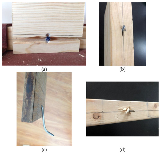
Figure 4.
Failure modes of the joints: (a) Brittle failure of SPF sheathing panel, (b) Brittle failure of screw, (c) Bending of nail, (d) Fatigue break of nail.
3.2. Load–Displacement Relationships
The load–displacement relationship curves of joints under monotonic and cyclic loads are shown in Figure 5. As shown in Figure 5, the hysteretic curves obtained from cyclic tests are below the load–displacement curve obtained from monotonic tests. The hysteretic curves of joints in the push and pull directions show significant differences. This is due to the anisotropy properties of wood material, and the angle between the loading direction and the wood grain having a great influence on the material properties of wood. Due to the gradual enlargement of the fastener hole in the framing material when the joints are subjected to cyclic loading, the hysteretic curves of the joints have a horizontal section at the beginning of the loading. Moreover, the hysteresis curve of joints presents an obvious ‘Z’ shape, which indicates that the cyclic performance of the joint is influenced by the slip [5,37].
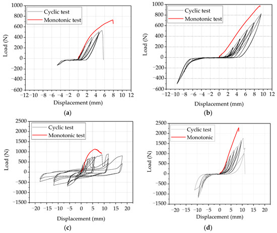
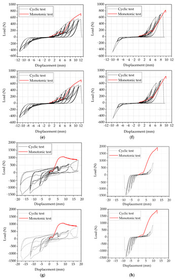
Figure 5.
Load–displacement curves of the test specimens: (a) CSN, (b) CSS, (c) CBN, (d) CBS, (e) PSN, (f) PSS, (g) PBN, (h) PSS.
3.3. Mechanical Performance
3.3.1. Ultimate Bearing Capacity
According to the Table 3, in monotonic tests, the ultimate bearing capacities of the SPF-nail, SPF-screw, and BS-nail perpendicular joints are slightly higher than those of the parallel joints by approximately 15%. The ultimate bearing capacity of the BS-screw perpendicular joints is 26% higher than that of parallel joints. In cyclic tests, the perpendicular joints with an SPF panel and the parallel joints with a BS panel show significant differences in push and pull direction loading. Conversely, the ultimate bearing capacity of the perpendicular joints with BS panels and parallel joints with SPF panels is relatively similar in push and pull loading. For perpendicular joints, the ultimate bearing capacity of the joints with BS panels is higher than the ultimate load capacity of the joints with SPF panels. The BS-screw joint has the highest ultimate bearing capacity in both push and pull loading. This shows that the use of BS panels and screws can make good use of their respective mechanical properties when the load is perpendicular to the grain direction of the framing material. For parallel joints, at the beginning of loading, the wood fibers split slightly in the loading direction, which results in a lag in the load-bearing capacity of the joint in the same cycle. Therefore, the load-bearing capacity of the joints with BS panels in the push direction is higher than that in the pull direction. However, for parallel joints with SPF panels, the load-bearing capacity of joints in the push direction was lower than that in the pull direction. This is due to the fact that the SPF panels reach the ultimate state of the joints in the pull direction, which results in an increased contribution from the tearing of the SPF panels in addition to the bending capacity of the fasteners. Additionally, it can be seen that the displacement corresponding to the ultimate bearing capacity of the PSB-nail joint is the largest, and the use of screws can reduce the displacement corresponding to the ultimate bearing capacity of the joint with BS panel.
Table 3.
Ultimate bearing capacity of joints.
3.3.2. Envelope Curves and Strength Degradation
According to the envelope curves of joints as shown in Figure 6, it can be seen that the envelope curves of nailed joints are nonlinear and those of screwed joints are linear. Moreover, there are distinct differences in the envelope curves between the push loading and pull loading. For perpendicular joints, the envelope curves have a near horizontal section at the beginning of the push loading. For the parallel joints, the type of sheathing panel determines whether the initial horizontal section of the curve appears to be loaded in the push or pull direction. The strength degradation ratio of joints is shown in Figure 6. It can be seen that the strength degradation ratio of the screwed joints is small, basically in the range from 0.8 to 1. In contrast, the strength degradation of nailed joints gradually increases with the number of cycles, in the range from 0.2 to 1. According to EN 12512 [38], the joints should be considered failed when the ratio is less than 0.8. Therefore, although the load–displacement curve of the BS-nail joints under monotonic load exhibits good ductility, the ductile properties of the BS-nail joints under cyclic loads should be reconsidered due to the strength degradation.
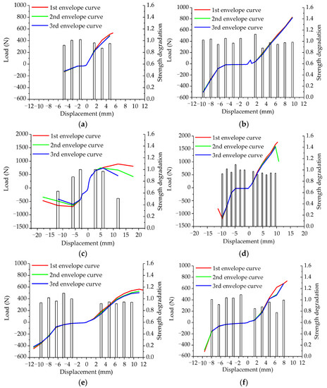
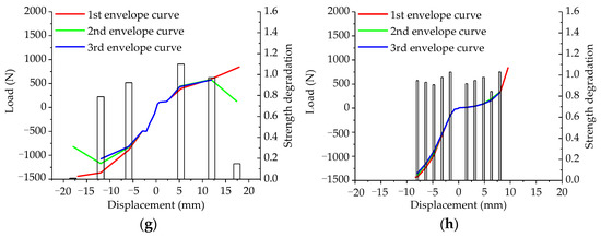
Figure 6.
Envelope curves and strength degradation of the test specimens: (a) CSN, (b) CSS, (c) CBN, (d) CBS, (e) PSN, (f) PSS, (g) PBN, (h) PSS.
3.3.3. Initial Stiffness and Stiffness Degradation
The initial stiffness of joints is shown in Figure 7. It can be seen that the initial stiffness of the joints under the pull and push loading has a significant difference, with the exception of the perpendicular screwed joints with a BS panel. This is due to the fact that wood is an anisotropic material, the wood fibers near the fastener are deformed and the fastener hole expands when subjected to cyclic loading, as shown in Figure 4b,d. The initial stiffness of the joints depends on the ultimate bearing capacity and the failure displacement of the joints, as shown in Equation (2). Due to the ultimate bearing capacity and the failure displacement of CSN joints being low, the calculation area of the initial stiffness of the CSN joints is chosen from the horizontal section of the envelope curve. Therefore, the initial stiffness of CSN joints is very low. For perpendicular joints, the initial stiffness of nailed joints is higher than that of screwed joints. Conversely, for parallel joints, the initial stiffness of screwed joints is higher than that of nailed joints.
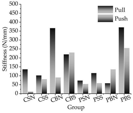
Figure 7.
Initial stiffness of the test specimens.
The effective stiffness of the joints is shown in Figure 8. It can be seen that the effective stiffness for the joints with a BS panel in the elastic loading phase is higher than that of the joints with an SPF panel. The effective stiffness degradation of the joints can be observed according to Figure 8. During the elastic loading phase, the effective stiffness of all joints decreases as the number of cycles increases. After the sixth cycle the effective stiffness of the screwed joints tends to increase, while the effective stiffness of the nailed joints continues to decrease. The nailed joints have the decreasing trend in effective stiffness and are subjected to less cyclic loading until failure. In contrast, the effective stiffness of the screwed joints tends to remain stable as the number of cycles increases and is able to withstand a higher number of cyclic loading. The effective stiffness of the joints with a BS panel is most affected by cyclic loading. It can be seen that the effective stiffness of the BS-nail joints is higher during the elastic loading phase, but the advantage of the effective stiffness of the BS-screw joints is more pronounced as the number of cycles increases. Joints with an SPF panel have less initial stiffness and weaker effective stiffness degradation, but can withstand more cycles than BS-nail joints.
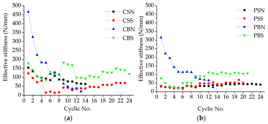
Figure 8.
Effective stiffness of the test specimens: (a) Perpendicular joints; (b) Parallel joints.
3.3.4. Equivalent Viscous Damping
The equivalent viscous damping is an important parameter to measure the seismic performance of a joint. The damping ratio, υeq = 0.05, represents the amount of viscous damping in a system relative to critical damping and is the most commonly used measure of viscous damping [4]. According to Figure 9, it can be seen that the equivalent viscous damping of the perpendicular nailed joints is lower at the beginning of the loading than that of the parallel nailed joints. The equivalent viscous damping of the nailed joints with a BS panel increases with the number of cycles, conversely, the equivalent viscous damping of the other joints decreases as the number of cycles increases. In the later stages of cyclic loading, the equivalent viscous damping of perpendicular joints is smaller than that of parallel joints.
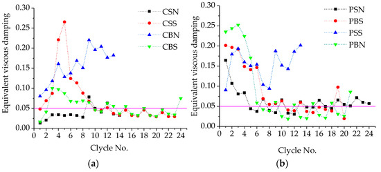
Figure 9.
Equivalent viscous damping of the test specimens: (a) Perpendicular joints; (b) Parallel joints.
3.4. Compared with Design Codes
The design values for the load-bearing capacity of joints, calculated according to the Chinese and European codes, are shown in Table 4. It can be seen that the design values of the load-bearing capacity calculated in accordance with the Chinese code are on the conservative side compared to the European design code. The design value of bearing capacity calculated in accordance with the Chinese design code is approximately 15% to 29% of the ultimate bearing capacity under monotonic loading, while the design value of bearing capacity calculated in accordance with the European design code is 34% to 64% of the ultimate bearing capacity under monotonic loading. This is due to the fact that the design values are calculated in accordance with the Chinese code without taking into account the cord effect and the withdrawal strength provided by the fastener. Compared to the ultimate bearing capacity of the joints with a BS panel under cyclic loading, the design values calculated by the Chinese code are 24–37% of the ultimate bearing capacity obtained from the test, and the design values calculated by the European code are 52–64% of the ultimate bearing capacity obtained from the test. For the joints with an SPF panel, the design value predicted by the Chinese design code is approximately 45% of the ultimate bearing capacity obtained from the test, and the design value predicted by the European code is in general agreement with the ultimate bearing capacity obtained from the test. This indicates that the Chinese design code underestimates the bearing capacity of the joints with a BS panel. This may lead to material wastage and excessive setting of screws in the design process, which could cause further brittle damage. In addition, the failure mode predicted by the Eurocode 5 is closer to the actual damage pattern of the joints in the tests. This is one of the reasons that the design values predicted by the Eurocode are similar to the ultimate bearing capacity obtained from the tests.
Table 4.
Comparison of calculated and experimental results of joints.
3.5. Reliability Results
The reliability index of the design value calculated by different methods are reported in Table 5 and Table 6. The results of the reliability analysis indicate that the reliability index increase nonlinearly with the increase of live to dead load ratio. The target reliability index specified in the Chinese code of members in light wood frame structures for an ultimate limit state is 3.2 and 3.7 (ductile failure and brittle failure, respectively). Based on the comparison of the reliability index of design bearing capacity determined by GB50005 with the target reliability index, the design method in GB50005 for sheathing-to-framing joints under monotonic loads is found to be over-conservative. However, the design method in GB50005 for sheathing-to-framing joints under cyclic loads is found to be unconservative. The reliability index of the design values calculated by GB50005 is approximately 1.54–3.78 higher than the that calculated by Eurocode 5. Existing studies clearly show that the reliability index of joints is within the range of β = 1.5 to β = 2.0 [12,39] thanks to the high redundancy of the light wood frame structures. The reliability index of design bearing capacity determined by Eurocode 5 achieved β > 1.5 under certain conditions. For joints under cyclic loads, the reliability index of design bearing capacity for joints with a BS panel determined by GB50005 is higher than 1.5.
Table 5.
Reliability index of the design values calculated by GB50005.
Table 6.
Reliability index of the design values calculated by Eurocode 5.
4. Discussion
4.1. Application Suggestions
The hysteretic curves of test joints show significant differences under push and pull loading. This phenomenon was also noticed in existing studies [21]. This may be attributed to the inconsistent force state on the fastener in joints under push and pull loading. The loading direction determined the deformation behavior of the fastener hole. As the compression capacity of the wood fiber is much higher than the shear capacity between the wood fibers, the deformation of the fastener hole in the parallel joints is greater than the deformation of the fastener hole in the perpendicular joints [40]. Similarly, the ultimate bearing capacity of perpendicular joints is higher than that of parallel joints, also because the framing material provides more compressive capacity under the same deformation conditions. Moreover, due to the low shear capacity of wood fibers, the wood fibers in the framing material of parallel joints are splintered and squeezed to the sides, which results in the low stiffness of parallel joints at the initial loading stage. The slope of the load–displacement curve becomes larger when the fastener is bent gradually after the wood fibers are squeezed denser. It is therefore proposed to add to the specification that important joints in light wood frame structures should be made in the wood fiber direction of the framing material perpendicular to the direction of the load.
In general, for wood and bamboo, the density of the material determines the properties of the material [19,20,22]. The material properties of the BS panels are much higher than those of SPF panels, which makes full use of the bending strength of the fasteners in the BS joints. Thus, the bearing capacity and stiffness of BS joints are higher than those of SPF joints. Compared with BS joints, SPF joints have high strength-to-weight ratio despite having a low bearing capacity. It is therefore recommended to use a material such as BS with better material properties in the main load-bearing joints of light wood frame structures. To reduce self-weight and further reduce seismic effects, the SPF panel can be applied in unimportant positions in the structure. However, due to the many factors influencing the material properties of timber, the strength of timber has a high degree of dispersion. The cyclic test results also show that the ultimate bearing capacity of the joints with an SPF panel has a high coefficient of variation. Therefore, the joints with an SPF panel should not be used in seismic components.
The yield strength of screws is higher than that of nails, as can be seen from the bending test of the fasteners. The ultimate bearing capacity of screwed joints is higher than that of nailed joints, not only because of the high bending strength of screws but also because of the high withdrawal strength of screws. Screwed joints have less stiffness in the initial loading stage because the threads of screws cut the wood fibers rather than screws bending. Even though the experimental results show good performance in terms of the strength and stiffness of a screwed joint, the ductility properties of this joint are very poor. However, the strength degradation and stiffness degradation of screwed joints are significantly lower than those of nailed joints. The load–displacement relationship of the nailed joints is nonlinear; in contrast, the load–displacement relationship of the screwed joints is linear. The nailed joints exhibit good ductility and damping due to the material of the nail having a pronounced yield step during flexure. It can be seen that nailed joints with appropriate sheathing panels used in conjunction have good energy dissipation. Using screws in sheathing-to-framing joints with a high-strength sheathing panel can take full advantage of the high withdrawal capacity of the screws and substantially enhance the ultimate bearing capacity of the joints [23,24]. It is therefore recommended to use a mixture of nails and screws in light wood frame structures for the balance between ductility and resistance requirements.
4.2. Design Suggestions
The materials used in the tests are all made in China, they are more in agreement with the Chinese statistical model of the survey. Therefore, the reliability index of joints investigated in this paper should meet the requirements of GB50005. The existing Chinese standard underestimates the design bearing capacity of joints under monotonic load in most cases. Moreover, the existing Chinese standard overestimates the design bearing capacity of joints under cyclic loads, which can increase the failure risk. Therefore, in order to meet reliability requirements based on safety and economy for design, the modification factors of resistance ηR considered varied parameters are applied to the joint design equation. In GB50005, the moisture content correction factor is considered when the moisture content of the components is higher than 15%, so the effect of moisture content is not considered in this study. Throughout this study, all modification factors are consistently determined at the target reliability index of β = 3.2 and β = 3.7 (ductile failure and brittle failure, respectively).
Therefore, the failure function can be rewritten as
Table 7 shows the modification factors which are needed to meet the target reliability index.
Table 7.
Modification factor values of joints.
According to the reliability results, it becomes clear that the modification factor is positively correlated with the live to dead load ratio. Moreover, the modification factor of the parallel joints is negatively correlated with the modification factor of the perpendicular joints. Therefore, the modification factor considered live to dead load ratio ηρ, is taken into account in the design formula for perpendicular joints. Based on the employment of ηρ, another modification factor ηld should be taken into account to ensure reliability level, which considers load direction. The modification factor of resistance can be expressed as
where ηld is the modification factor considered loading direction, and ηρ is the modification factor considered live to dead load ratio.
An equation, as shown in Equation (23), representing the relationship between ρ and ηρ was established.
Due to the lower embedding capacity of an SPF panel, the fastener strength cannot be fully taken advantage of. Thus, ηρ for an SPF joint is not distinguished according to fastener types. Due to the resistance capacity of BS joints being mostly governed by the bending performance of fasteners, ηρ for BS joints is distinguished between the nail and screw. Different values of ηρ corresponding to different situations are recommended and summarized as in Equations (23)–(26). The value of ηlp is reported in Table 8.
Table 8.
Value of modification factor ηlp.
For SPF joints under monotonic loads
For BS-nail joints under monotonic loads
For BS-screw joints under monotonic loads
For BS joints under cyclic loads
The modification factors of the resistance of joints were calculated according to Formulas (24)–(27). Then, the calculated results were compared with the reliability analysis results, both of which are shown in Figure 10. The calculated results are in good agreement with the analysis results, according to Figure 10. Consequently, the modification factors presented in this paper represent a high calculation accuracy for sheathing-to-framing joints with variable conditions, indicating that the proposed modification factors can be successfully employed as a design rule for predicting the bearing capacity of sheathing-to-framing joints with an SPF panel and a BS panel, respectively.
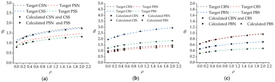
Figure 10.
Fitting curves of modification factor of resistance for joints: (a) Joints with SPF panel; (b) Joints with BS panel under monotonic load; (c) Joints with BS panel under cyclic load.
5. Conclusions
In this paper, monotonic and cyclic loading tests were carried out on sheathing-to-framing joints in order to expand the application of SPF panels and BS panels in light wood frame structures. The effects of loading direction, type of sheathing panel, and type of fastener on the mechanical properties of sheathing-to-framing joints were investigated. The results of the study provide basic data to enhance the engineering application of SPF panels and BS panels. The following conclusions were drawn:
The angle between the loading direction and the timber grain has a large influence on the load-bearing capacity and stiffness of the joints at the initial loading stage. Joints with an SPF panel do not make full use of the bending strength of the fasteners, but joints with a BS panel make full use of the bending strength of the fasteners. Nailed joints show higher strength and stiffness degradation under cyclic loads than screwed joints. However, the ductility and energy dissipation capacity of nailed joints are better than those of screwed joints.
Based on the test and reliability analysis results, it is suggested that the joints with a BS panel can be applied in light wood frame structures as mainly bearing elements. However, it is practicable that the joints with an SPF sheathing panel can be applied in light wood frame structures as unimportant elements. When the component in a light wood frame structure is designed as a mainly seismic component, the sheathing panel should not use an SPF panel.
The reliability investigations on a wide variety of joints show that the consideration of modification factors is indispensable to ensure the reliability index of joints. According to different failure modes, the modification factors for design bearing capacity of joints determined by Chinese code (GB50005) were proposed. The modification factor was derived in relation to the design equation for a frame-to-sheathing connection, which allows the reliability index of joints to achieve the target reliability index of β = 3.2 and β = 3.7.
Author Contributions
Conceptualization, H.Z. and J.D.; methodology, H.Z. and J.D.; validation, H.Z. and J.D.; formal analysis, J.D.; investigation, J.D.; resources, H.Z.; data curation, J.D.; writing—original draft preparation, J.D.; writing—review and editing, H.Z.; funding acquisition, H.Z. and J.D. Both authors have read and agreed to the published version of the manuscript.
Funding
This research was funded by Science Foundation of Heilongjiang Province (LH2020E009), and Special Project for Double First-Class-Cultivation of Innovative Talents (000/41113102).
Institutional Review Board Statement
Not applicable.
Informed Consent Statement
Not applicable.
Data Availability Statement
The data presented in this study are available on request from the corresponding author. The data are not publicly available due to restriction of privacy.
Acknowledgments
We would like to thank the anonymous reviewers and editor for their valuable comments and suggestions for improving the quality of this paper.
Conflicts of Interest
The authors declare no conflict of interest.
References
- Izzi, M.; Polastri, A. Low cycle ductile performance of screws used in timber structures. Constr. Build. Mater. 2019, 217, 416–426. [Google Scholar] [CrossRef]
- Hu, W.; Chen, B. A Methodology for Optimizing Tenon Geometry Dimensions of Mortise-and-Tenon Joint Wood Products. Forests 2021, 12, 478. [Google Scholar] [CrossRef]
- Tahmasebinia, F.; Ma, Y.; Joshua, K.; Sepasgozar, S.M.; Yu, Y.; Li, J.; Sepasgozar, S.; Marroquin, F.A. Sustainable Architecture Creating Arches Using a Bamboo Grid Shell Structure: Numerical Analysis and Design. Sustainability 2021, 13, 2598. [Google Scholar] [CrossRef]
- Jayamon, J.R.; Line, P.; Charney, F.A. State-of-the-Art Review on Damping in Wood-Frame Shear Wall Structures. J. Struct. Eng. 2018, 144. [Google Scholar] [CrossRef]
- Guíñez, F.; Santa María, H.; Almazán, J.L. Monotonic and cyclic behaviour of wood frame shear walls for mid-height timber buildings. Eng. Struct. 2019, 189, 100–110. [Google Scholar] [CrossRef]
- Bagheri, M.M.; Doudak, G. Structural characteristics of light-frame wood shear walls with various construction detailing. Eng. Struct. 2020, 205. [Google Scholar] [CrossRef]
- Pang, W.; Hassanzadeh Shirazi, S.M. Corotational Model for Cyclic Analysis of Light-Frame Wood Shear Walls and Diaphragms. J. Struct. Eng. 2013, 139, 1303–1317. [Google Scholar] [CrossRef]
- Guo, S.; He, M.; Li, Z.; Liang, F.; Chen, F.; Sun, Y.; Briseghella, B.; He, G. Lateral performance of midply wood shear walls with anchor tie-down system: Experimental investigation and numerical simulation. Constr. Build. Mater. 2020, 235. [Google Scholar] [CrossRef]
- Di Gangi, G.; Demartino, C.; Quaranta, G.; Monti, G. Dissipation in sheathing-to-framing connections of light-frame timber shear walls under seismic loads. Eng. Struct. 2020, 208. [Google Scholar] [CrossRef]
- Sartori, T.; Tomasi, R. Experimental investigation on sheathing-to-framing connections in wood shear walls. Eng. Struct. 2013, 56, 2197–2205. [Google Scholar] [CrossRef]
- Sadeghi Marzaleh, A.; Steiger, R. Experimental investigation of OSB sheathed timber frame shear walls with strong anchorage subjected to cyclic lateral loading. Eng. Struct. 2021, 226. [Google Scholar] [CrossRef]
- Seim, W.; Kramar, M.; Pazlar, T.; Vogt, T. OSB and GFB as Sheathing Materials for Timber-Framed Shear Walls: Comparative Study of Seismic Resistance. J. Struct. Eng. 2016, 142. [Google Scholar] [CrossRef]
- Poletti, E.; Vasconcelos, G.; Branco, J.M.; Koukouviki, A.M. Performance evaluation of traditional timber joints under cyclic loading and their influence on the seismic response of timber frame structures. Constr. Build. Mater. 2016, 127, 321–334. [Google Scholar] [CrossRef] [Green Version]
- Gu, J. Seismic Reliability Analysis of Wood Shear Walls Using Different Methods. J. Struct. Eng. 2014, 140. [Google Scholar] [CrossRef]
- Premrov, M.; Dobrila, P. Numerical analysis of sheathing boards influence on racking resistance of timber-frame walls. Adv. Eng. Softw. 2012, 45, 21–27. [Google Scholar] [CrossRef]
- Judd, J.P.; Fonseca, F.S. Analytical Model for Sheathing-to-Framing Connections in Wood Shear Walls and Diaphragms. J. Struct. Eng. 2005, 131, 345–352. [Google Scholar] [CrossRef] [Green Version]
- Peng, C.; El Damatty, A.A.; Musa, A.; Hamada, A. Simplified numerical approach for the lateral load analysis of light-frame wood shear wall structures. Eng. Struct. 2020, 219. [Google Scholar] [CrossRef]
- Lafontaine, A.; Chen, Z.; Doudak, G.; Chui, Y.H. Lateral Behavior of Light Wood-Frame Shear Walls with Gypsum Wall Board. J. Struct. Eng. 2017, 143, 04017069. [Google Scholar] [CrossRef]
- Mirra, M.; Ravenshorst, G.; de Vries, P.; van de Kuilen, J.-W. An analytical model describing the in-plane behaviour of timber diaphragms strengthened with plywood panels. Eng. Struct. 2021, 235, 112128. [Google Scholar] [CrossRef]
- Jockwer, R.; Fink, G.; Khler, J. Assessment of the failure behaviour and reliability of timber connections with multiple dowel-type fasteners. Eng. Struct. 2018, 172, 76–84. [Google Scholar] [CrossRef]
- Echeverry, J.S.; Correal, J.F. Cyclic behavior of Laminated Guadua Mat sheathing-to-framing connections. Constr. Build. Mater. 2015, 98, 69–79. [Google Scholar] [CrossRef]
- Li, Z.; Xiao, Y.; Wang, R.; Monti, G. Studies of Nail Connectors Used in Wood Frame Shear Walls with Ply-Bamboo Sheathing Panels. J. Mater. Civ. Eng. 2015, 27. [Google Scholar] [CrossRef]
- Wang, R.; Xiao, Y.; Li, Z. Lateral Loading Performance of Lightweight Glubam Shear Walls. J. Struct. Eng. 2017, 143. [Google Scholar] [CrossRef]
- Zheng, W.; Li, Y.; Zhou, Y.; Zhu, Y.; Lu, W.; Liu, W.; Wang, H. Experimental investigation on the behavior of plybamboo sheathing-to-framing screwed connections. Constr. Build. Mater. 2020, 262. [Google Scholar] [CrossRef]
- Rao, F.; Ji, Y.; Huang, Y.; Li, N.; Zhang, Y.; Chen, Y.; Yu, W. Influence of resin molecular weight on bonding interface, water resistance, and mechanical properties of bamboo scrimber composite. Constr. Build. Mater. 2021, 292, 123458. [Google Scholar] [CrossRef]
- Chen, J.; Wang, H.; Yu, Y.; Liu, Y.; Jiang, D. Loosening of Bolted Connections under Transverse Loading in Timber Structures. Forests 2020, 11, 816. [Google Scholar] [CrossRef]
- GB50005-2017. Code for Design of Timber Structures; Ministry of Construction of the People’s Republic of China: Beijing, China, 2017.
- EN 1995-1-1. Eurocode 5: Design of Timber Structures—Part 1-1: General-Common Rules and Rules for Buildings; European Committee for Standardization CEN: Bruxelles, Belgium, 2004. [Google Scholar]
- Wei, Y.; Tang, S.; Ji, X.; Zhao, K.; Li, G. Stress-strain behavior and model of bamboo scrimber under cyclic axial compression. Eng. Struct. 2020, 209, 110279. [Google Scholar] [CrossRef]
- ISO 10984. Timber Structures—Dowel-Type Fasteners—Part 2: Determination of Embedding Strength; ISO: Geneva, Switzerland, 2007. [Google Scholar]
- ASTM F1575-03. Standard Test Method for Determining Bending Yield Moment of Nails; ASTM International: West Conshohocken, PA, USA, 2013. [Google Scholar]
- ASTM D1761. Standard Test Methods for Mechanical Fasteners in Wood; ASTM International: West Conshohocken, PA, USA, 2012. [Google Scholar]
- ISO 16670. Timber Structures—Joints Made with Mechanical Fasteners—Quasi-Static Reversed-Cyclic Test Method; ISO: Geneva, Switzerland, 2003. [Google Scholar]
- Johnston, A.R.; Dean, P.K.; Shenton, H.W., III. Effects of Vertical Load and Hold-Down Anchors on the Cyclic Response of Wood Framed Shear Walls. J. Struct. Eng. 2006, 132, 1426–1434. [Google Scholar] [CrossRef]
- Nikolaidis, E.; Ghiocel, D.M.; Singhal, S. Engineering Design Reliability Handbook; CRC Press: Boca Raton, FL, USA, 2004. [Google Scholar]
- Zhang, X.; Shahnewaz, M.; Tannert, T. Seismic reliability analysis of a timber steel hybrid system. Eng. Struct. 2018, 167, 629–638. [Google Scholar] [CrossRef]
- Estrella, X.; Malek, S.; Almazán, J.L.; Guindos, P.; Santa María, H. Experimental Study of the Effects of Continuous Rod Hold-Down Anchorages on the Cyclic Response of Wood Frame Shear Walls. Eng. Struct. 2021, 230. [Google Scholar] [CrossRef]
- EN 12512:2001. Timber Structures—Test Methods-Cyclic Testing of Joints Made with Mechanical Fasteners; European Committee for Standardization CEN: Bruxelles, Belgium, 2001. [Google Scholar]
- Schick, M.; Seim, W. Overstrength values for light frame timber wall elements based on reliability methods. Eng. Struct. 2019, 185, 230–242. [Google Scholar] [CrossRef]
- Mehta, M.; Scarborough, W.; Armpriest, D. Building Construction: Principles, Materials, and Systems; Pearson: Upper Saddle River, NJ, USA, 2007. [Google Scholar]
Publisher’s Note: MDPI stays neutral with regard to jurisdictional claims in published maps and institutional affiliations. |
© 2021 by the authors. Licensee MDPI, Basel, Switzerland. This article is an open access article distributed under the terms and conditions of the Creative Commons Attribution (CC BY) license (https://creativecommons.org/licenses/by/4.0/).