Abstract
Cable tensile forces in winch-assist harvesting have been investigated in order to assess the safety concerns of the technology. However, the literature is lacking, particularly in regards to the impact of winch design. In this study, a Summit Winch Assist tethering a feller-director on ground slopes up to 77% was monitored for four days. The cable tensile forces were simultaneously recorded at the harvesting and anchor machine at a frequency of 100 Hz. Cameras and GNSS devices enabled a time study of the operations and the recording of machine positions. Winch functionality and design were disclosed by the manufacturer and used for the interpretation of the results. The cable tensile forces reached 296 kN at the harvesting machine and 260 kN at the anchor machine. The slow negotiation of obstacles while moving downhill recorded the highest peaks, mainly due to threshold settings of the winch in the brake system activation. Lower but significant peaks were also recorded during stationary work tasks. The peaks, however, were limited to a few events and never exceeded the endurance limit of the cable. Overall, the study confirmed recent findings in cable tensile force analysis of active winch-assist operations and provided evidence of the underlaying mechanisms that contribute to cable tensile forces.
1. Introduction
Forest managers in the Pacific North West (PNW) are evermore relying on steep, challenging terrain for timber harvesting because of the over exploitation of easy-access stands, fibre shortage, extended natural disturbance, and increasing demands on the timber harvesting land base (e.g., environmental protection, recreational demands, etc.) [1,2]. In this context, safety and production concerns in traditional steep slope harvesting systems (i.e., hand falling and cable logging) have led to the development and rapid adoption of winch-assist technology in the region [3,4,5].
Winch-assist harvesting systems, also referred to as tethered harvesting systems, originated as early as the 1990′s in Europe, and allow operators to deploy ground-based machinery on steep slopes due to an increase in tractive force, achieved by tethering forest machines (e.g., harvesting, forwarding, or skidding machines) to a stable anchor [6,7,8,9]. Initial studies suggest that modern tethered harvesting solutions can often be less expensive, more productive, and have a lower worker safety risk when compared with conventional cable-based harvesting [4,10,11,12,13,14,15,16].
There are two main categories of winch-assist systems, integrated-winch (synonymous with “static” or “passive” systems) and anchor-based (synonymous with “dynamic” or “active” systems) [1,7,15,17]. Integrated-winch systems employ a winch that is mounted directly onto a ground-based forest machine, with the winch cable being anchored upslope from the working area. Similar to cable logging, trees and stumps are typically used as anchors and require both an appropriate set-up and a stability assessment [18,19,20,21,22]. Anchor-based winch configurations employ a winch that is installed onto an anchor machine (synonymous with a “base machine”) which remotely spools cable to a ground-based forest machine tethered below. While both integrated and anchor-based winch-assist configurations are currently being employed throughout the PNW, anchor-based systems are growing in popularity amongst operators and have become the predominant technology for tethered harvesting in the region. Some of the benefits implicit to anchor-based technologies are realized through the ability to employ more powerful winches and larger cables, as well as the ease of set-up and enhanced reliability of the anchoring solutions [1,7,15,23,24,25].
Alongside the adoption of these relatively novel winch-assisted harvesting solutions must come the development of robust safety protocols that can ensure the safe and effective implementation of this technology [6,12]. One of the outstanding knowledge gaps and key safety considerations in these operations is the integrity of the wire rope which is used to tether the forest machine to its anchor [4,12,26]. It is well understood that the dynamic nature of forest machines can create peak tensile force events that may result in cable fatigue and, eventually, failure. However, there is little understanding of how commonly these peak events occur during normal operational conditions, nor the mechanisms that cause them.
In order to understand the frequency, magnitude, and duration of such peak events, researchers began conducting cable tensile force studies on winch-assisted harvesting operations, where high-capacity load cells are used to measure cable tensile forces for various forest machines (e.g., [23,26,27,28,29,30,31,32]). Cable tensile forces for both integrated-winch configurations and anchor-based configurations have been monitored and described in both technical reports and scientific publications. Depending on the winch technology being observed and the study layout, these studies monitor cable tensile forces at either the forest machine, the anchor/anchor machine, or both simultaneously, then analyse the time series in order to determine the cable tensile force distributions and peak values that may have occurred. By integrating a simultaneous time-and-motion study alongside cable tensile force monitoring, researchers have been able to associate tensile force patterns and peak events with the operational tasks that created them. One of the key findings of these studies is that movement work tasks are more commonly responsible for producing peak tensile force events (although some technologies seem more capable of attenuating peaks than others) [26]. Simultaneous observations of cable tensile forces at both the forest machine and the anchor machine in active winch-assist harvesting have also shown that significant differences can be observed between the two machines [33]. This discrepancy reflects the force dampening which results from friction along the cable (from ground, stumps, or rub trees) and is not consistent over time, with the highest relative tensile force alternating between the forest machine and its anchor throughout the time series [26,32,34].
Although these tensile force studies provide a valuable analysis of tensile force distribution, peak events, and exceedance of safety limits, they are limited in their ability to provide a functional understanding of how operational factors influence the observed tensile forces. For example, factors such as operator experience and machine settings have been identified as potentially having a strong influence over the tensile forces experienced in the cable, with implications for both the longevity of the rope and the safety of the operations [4,26,30]. Furthermore, no studies have explicitly evaluated the mechanics of the winch system being employed in order to understand how different winch design and settings contribute to the resulting cable tensile forces.
This paper contributes to the knowledge gap outlined above by analysing the cable tensile forces of an active winch-assist harvesting operation and investigating how the design and settings of the winch technology being employed influence cable tensile forces during various work tasks. By combining tensile force monitoring, a time-and-motion study, and a detailed analysis of the winch system, this progression of cable tensile force research provides evidence of how winch design can impact the overall cable tensile force distribution (including differences between the harvesting and anchor machines, and frequency in exceeding recommended safety limits) with the overall goal to inform best practices and improve the safety for operators in winch-assist operations.
2. Materials and Methods
2.1. Study Site and Harvesting Operations
The site was located on a 72-ha cut block near Raymond, Washington (USA). The study was carried out in February of 2020 and included four consecutive days of observation of tethered harvesting operations. The harvest area was a 60-year-old second growth forest with a standing merchantable timber volume of 615 m3 ha−1. The species composition of the stand was 75% western hemlock (Tsuga heterophylla) and 25% Douglas fir (Pseudotsuga menziesii), with minimal understory regeneration. The soil in the harvest area was well drained, silty loam, with minimal coarse fragments or exposed bedrock.
The harvesting operation was fully mechanised and employed both conventional and winch-assisted machines. Winch-assist harvesting was limited to the steepest areas of the block, with an average ground slope of 45% and maximum slopes of 77% (Figure 1). During winch-assist harvesting, the trees were mostly felled facing downhill, piling trees into bunches in order to optimize the subsequent cable yarding operations. During the observation period, three different anchor machine positions were used. Because of the ground morphology and anchoring location, the tethered machine also employed four redirecting stumps where the cable was oriented on one side of a robust stump, providing lateral deflection and allowing the harvesting machine to operate more effectively on the alternate aspect slopes. Various rub trees were also used in case of more limited deviations.
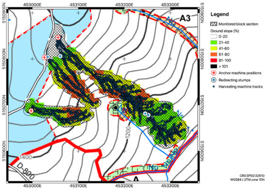
Figure 1.
Extract of the harvest area map with evidence of harvesting and anchor machine positions, redirecting stumps position, and ground slope for the block section during the trial. Contour lines are in feet (1000 ft = 304.8 m).
The operator of the tethered harvesting machine had four years of experience in winch-assist operations and was assisted by a second operator who provided safety support and aided in the system setup (e.g., moving the anchor machine).
2.2. Machine and Winch Functionality Description
The observed winch-assist equipment was comprised of a 2015 CAT® 552-2 tracked feller-director (forest machine, hereafter named “harvesting machine”) tethered by a 2004 CAT® 330C-L tracked excavator equipped with a 2015 Summit Winch Assist system (“anchor machine”) (Figure 2). The harvesting machine was powered by a 226 kW engine and had a total operating mass of roughly 37 tonnes. The machine was equipped with a SATCO® boom and Waratah FL85 directional felling head. The feller-director was specifically designed for steep slope harvesting, with an anchoring point for tethered operations, levelling cab, extended tracks, and extended grousers for increased traction.
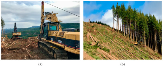
Figure 2.
Winch-assist operations based on a Summit Winch Assist system tethering a feller director: (a) View from the landing of the initial phase of the winch-assisted operations; (b) View of the harvesting operations. Note the anchor machine on top of the hill and the harvesting machine at the bottom right.
The anchor machine had a total estimated mass, including the cable and the winch system, of 41 tonnes and an engine power capacity of 182 kW. The winch of the anchor machine was composed of a hydraulically-driven, single drum capable of 196 kN of pulling force [35]. The cable was a brand new 565 m long 25.4 mm 6 × 26 IWRC swaged wire rope, rated with a Minimum Breaking Strength (MBS) of 711 kN. A 3 m long stud-link chain and shackles were used to fix the cable to the harvesting machine.
Summit Winch Assist: Main Components and Functionality
The Summit Winch Assist anchor machine observed in this study uses a Parker Hannifin V14 variable displacement bent axis hydraulic piston motor to drive a LANTEC® 540 winch [35]. The hydraulic motor has two sets of controls. The first provides continuously variable displacement dependent on the applied hydraulic pilot pressure or current that is applied on the pedals. The second set of controls are similarly activated by either the applied hydraulic pilot pressure or current. However, these controls only provide the maximum or minimum pump displacement and are used for controlling cable movements on and off the drum [36]. The winch has three planetary gear reductions, a sprag clutch (i.e., a one-way freewheel clutch), and a spring-applied, hydraulic-released, multidisc brake (i.e., a wet clutch) [37].
The sprag clutch is used in a backstop application. The inner race of the sprag clutch connects the hydraulic drive motor’s output shaft to the input shaft of the planetary drum drive. The outer race of the sprag clutch is attached to the wet clutch. When winding the cable onto the drum, the wet clutch is closed and the sprag clutch free wheels, allowing the inner race to be rotated by the hydraulic motor output shaft, which rotates the planetary gear input shaft. If torque is removed from the hydraulic motor output shaft, the force in the cable will cause the drum to rotate in the opposite direction. This will cause the sprags to jam in the sprag clutch [38], locking the inner race to the outer race. With the wet clutch closed, this holds the drum and prevents the rotation of the cable off direction. A schematic overview of the rotation path through a planetary winch is available at Winches Inc [39].
Dynamic braking uses the hydraulic motor and a valve assembly to control the rate that the cable is let off of the drum [39]. The valve assembly has a control valve with three positions: hoist (cable winded onto the drum), neutral (drum prevented from rotating), and lower (cable off the drum). There is a check valve that permits oil flow to the hydraulic motor when the control valve is in hoist position but is closed otherwise. There is a spool valve that comes into play for the neutral and lower positions. In the neutral position, the spool valve is closed, blocking oil from flowing out of the hydraulic motor. Note that while in the neutral position, the wet clutch is still closed. Thus, in the neutral position the drum is held stationary. With the control valve in the lower position (i.e., to let cable off the drum), the wet clutch release valve is opened at a lower pressure than the spool valve, which results in the wet clutch releasing before the spool valve begins to open. With the control valve in the lower position, pressure is fed into the end of the spool valve. When the pressure is sufficient to overcome the spring in the spool valve, the piston shifts and begins to permit flow out of the hydraulic motor. Varying the pressure adjusts the opening of the spool valve and this controls the flow out of the hydraulic motor which, in turn, controls the lowering rate (i.e., the rate the that cable comes off the drum).
The observed Summit Winch Assist also includes a band brake applied directly to the drum flange which is spring-applied and hydraulic-released [35]. This band brake is used as a safety backup system and is applied whenever the winch is not in active use (i.e., when the cable is not moved on or off the drum) or when there is a runaway condition (i.e., cable coming off the drum at an uncontrolled rate with a speed, measured at the anchor machine fairlead, exceeding a defined threshold). Otherwise, the band brake is off (hydraulic pressure release) for normal use of the system.
The threshold for pilot pressure magnitude in the pedals of the harvesting machine (or any other forest machine) that will engage the winch or dynamic braking can be adjusted by the operator. Increasing the lag (i.e., the difference between beginning to rotate the harvesting machine travel motors and beginning to operate the winch or dynamic braking) while traveling away from the anchor machine will permit the harvesting machine to make small steering corrections without releasing the brake.
2.3. Data Collection and Data Analysis
The methods used to collect and analyse the data in this study largely follow the novel procedure described by Mologni et al. [5,26,33]. The cable tensile forces were measured simultaneously at both the harvesting and anchor machines for the entirety of the study. At the harvesting machine, the cable tensile forces were measured using a pre-calibrated load cell installed between the stud link chain and the harvesting machine. The load cell was connected to a data logger (Campbell Scientific® CR1000x) set to record at 100 Hz. The datalogger and its power supply package were installed directly onto the harvesting machine’s undercarriage.
The cable tensile forces at the anchor machine were monitored by recording the signal produced by a load pin integrated in the top shave of the machine mast (the pin supporting the sheave is instrumented with strain gauges). The load pin calibration was checked at the beginning of the field study by the manufacturer using a pre-calibrated load cell to confirm that the cable tensile force was reported correctly in the readout from the cab of the anchor machine. The cable tensile force values measured by the load pin were then continuously displayed in the control panel of both the anchor and harvesting machine. To collect continuous tensile force data from the anchor machine system, the signal from the integrated load pin was fed directly into a second datalogger (Campbell Scientific® CR1000x), recording at a frequency of 100 Hz.
In order to convert the load pin signal into tensile force, it was necessary to develop a calibration equation where the tensile force is a linear function of the millivolt signal recorded by the datalogger. To generate the data for the calibration equation, in-cab video recording of the control display (showing tensile force values measured by the anchor machine’s load pin) was used to select 63 sample points at steady tensile force values which were then paired with recorded load pin signals. These points were used to generate a linear calibration equation. The tensile forces reported for the anchor machine in this study (expressed in kN) were found by applying the calibration equation to the millivolt signal from the load pin.
In-cab videos were also recorded at the harvesting machine in order to carry out a detailed time-and-motion study which detected the various work tasks, productive time including delays up to 15 min (PMH15), and delay-free productive time (PMH0). Work tasks and related priorities (in the case of overlapping work elements, the element with higher priority—lower priority value was recorded) considered in the present study were defined as follows:
- Felling: time spent felling trees, starting from the initial swing of the boom and finishing at the released of the felled trees (priority 4);
- Hoe-chucking: time spent bucking, bunching, and shovelling the felled trees, starting from the initial swing of the boom or the initial release of a felled tree and finishing at the final release of the moved trees (priority 4);
- Other-boom-movements: time spent brushing or clearing the trail from stumps and other obstacles, and time spent grabbing trees as support for climbing the hill, starting from the initial swing of the boom and finishing when releasing branches, trees, or stumps, as appropriate (priority 4);
- Moving-in: time spent moving toward the anchor machine (normally uphill), starting when at least one of the tracks begin to move and finishing when both tracks stopped (priority 2);
- Moving-out: time spent moving away the anchor machine (normally downhill), starting when at least one of the tracks begin to move and finishing when both tracks stopped (priority 2);
- Turning: time spent changing direction of the harvesting machine, moving only one track or both tracks in opposite directions, starting when at least a track begins to move and finishing when both tracks stopped, or at the beginning of another task (priority 3);
- Set-up: time spent by the operator to adjust winch and machine settings or time spent to move the cable over obstacles using the boom and harvesting head (priority 1);
- Delay: time not related to productive time, including personal, operational, and mechanical delays up to 15 min (priority 5).
Felling, hoe-chucking, and other-boom-movements are here aggregated as “stationary work elements”, considering that they do not involve active cable movements. Moving-in, moving-out, and turning are aggregated as “moving work elements”, for which a direct cable movement is expected. Delays are excluded from the results and discussion.
The location of the harvesting machine was continuously recorded at a frequency of 1 Hz using a Garmin GPSMAP® 64sx GNSS connected to a roof top external antenna. Anchor machine positions, as well as the position of the redirecting stumps used during the operations, were collected at the end of each work day using the same GNSS device. A 10 m resolution digital elevation model provided ground topography information.
The synchronization of cable tensile force data with video observations and machine positions was based on the Network Time Protocol accessed by means of the Emerald Time app for IOS mobile device. The camera used for recording the logging operations included a time stamp. Sample videos were collected at the beginning of each work day, which recorded the clock time of the mobile device simultaneously with the clock time of the dataloggers (shown on a field laptop by PC400, a Campbell Scientific® software). If needed, clock time from the video time stamps and/or dataloggers were corrected by relative difference from the clock time of the mobile device. Clock time related to the machine position recorded by GNSS device was assumed correct and the same as those collected by means of Network Time Protocol. All the data and information available (e.g., cable tensile forces, time-and-motion study, machine positions, ground information) were processed and analysed by means of GIS software and R-scripts [40,41]. The detailed description of the winch functionality was used for the interpretation of the results.
3. Results
The study covered a total of 17.4 PMH15 over four consecutive days, providing more than 6.25 million tensile force data values at both the anchor and harvesting machine. Delays up to 15 min represented 23.3% of the productive time and reduced the delay-free productive time to 13.3 PMH0. Moving work elements, including moving-in (18.2%), moving-out (13.8%), and turning (1.1%), covered a total of 33.1% of the delay-free productive time. Stationary work tasks, including felling (33.2%), hoe-chucking (5.8%), and other-boom-movements (24.4%), represented 63.4% of the delay-free productive time. Set-up time accounted for 3.6%.
3.1. Observed Cable Tensile Forces at the Harvesting and Anchor Machines
During stationary work elements (i.e., felling, hoe-chucking, and other-boom-movements), the average cable tensile forces observed at the harvesting machine ranged from 70 to 77 kN, the 95th percentile values ranged from 130 to 137 kN, and the peak values (maximum tensile forces) ranged from 193 to 280 kN (Table 1). During the same work elements, average cable tensile forces at the anchor machine ranged from 68 to 83 kN, reached 95th percentile from 113 to 141 kN, and had peak values from 158 to 223 kN (Table 2).

Table 1.
Cable tensile forces recorded at the harvesting machine.
Table 2.
Cable tensile forces recorded at the anchor machine.
Peak values per work element were always higher at the harvesting machine compared to those at the anchor machine by at least 35 kN, with a maximum difference of 57 kN during other-boom-movements. However, in terms of local differences between the cable tensile forces recorded at the two machines, the values recorded during stationary work elements were either higher at the harvesting or the anchor machine, depending on the local conditions (Table 3). Note that a reliable and conservative approach for describing the trends in the local differences between the two machines should refer to the 0.05 and 0.95 quantiles instead of the minimum and maximum differences, as suggested by Mologni et al. [26].
Table 3.
Local differences in cable tensile forces between the harvesting and anchor machine.
Cable tensile forces recorded at the harvesting machine during moving work elements (i.e., moving-in, moving-out, and turning) averaged from 55 to 65 kN and recorded 95th percentile values lower than 128 kN (Table 1). Peak values, however, were generally similar or higher than those related to stationary work elements and reached values between 274 and 296 kN, recording the absolute maximum tensile force of the whole dataset during moving-out. At the anchor machine, excluding set-up, moving elements reported both the highest and lowest average tensile force values, recording 89 kN during moving-in and 55 kN during moving-out (Table 2). While moving-out reported the lowest average value (excluding set-up), it also recorded the maximum tensile force, reaching 260 kN.
Moving elements were responsible for the highest peaks, even at the anchor machine, but recorded values 36–52 kN lower than those recorded at the harvesting machine. Local discrepancies between cable tensile forces at the harvesting and anchor machine during moving elements reached values as high as ±132 kN (Table 3). The majority of the data recorded during moving-in showed higher tensile forces at the anchor machine. Moving-out showed the opposite, with the majority of the recorded forces higher at the harvesting machine.
Set-up mostly accounts for the harvesting machine using its harvesting head to move the cable over obstacles. The operator intentionally reduced the tensile force in the cable to support this procedure and, as such, the forces monitored during this work element were generally very low (a mean of 12 kN at the harvesting machine and 20 kN at the anchor machine). The high tensile forces observed during set-up (mean 165 kN at the harvesting machine and 38 kN at the anchor machine) are linked to a single event where the harvesting machine assessed its position (moving for a fraction of a second) following a relocation of the cable over a stump.
3.2. Exceeding of the Recommended Safety Limits
Safety limits in winch-assist harvesting, and in general in any cable-supported harvesting system, include the Safe Working Load (SWL), here defined as one third of the MBS of the cable, and the endurance limit, defined as half of the MBS [42]. Schaare et al. [23] also suggested another limit, defined as 1.25 SWL (SWL 25%), which represent the overloading of the cable within the endurance limit.
Overall, the maximum cable working load (peak values relative to the MBS) observed during the study was limited to 41.6% of the MBS, and was measured at the harvesting machine during moving-out. Neither the endurance limit nor SWL 25% were exceeded during the observations. The cable tensile forces at the harvesting machine exceeded the SWL (237 kN) for 14.06 s, which represent 0.03% of the delay-free productive time. Exceedance of SWL was primarily recorded during stationary work elements, which represent 59.5% of the time over the SWL. However, the maximum tensile force values recorded when stationary work elements were limited to 280 kN, and the highest peaks and associated SWL exceedance at the harvesting machine were recorded during moving work elements, particularly during moving-out and turning (downhill-facing). At the anchor machine, the lower cable tensile forces were reflected by less time in exceedance of the SWL, which accounted for a total of 1.33 s (0.003% of the delay-free productive time). Exceeding of SWL at the anchor machine only occurred during moving work elements, particularly during moving-out and turning.
3.3. Winch Operations and Tensile Force Implications during Stationary Work Elements
During stationary work elements, the band brake was on and the winch was not activated. This configuration, as expected, led to limited increments in the cable tensile force during various stationary tasks. Stationary work elements that follow a moving phase, for example, showed a limited steady increment in the cable tensile forces because of the position assessment of the harvesting machine (short sliding). Higher tensile force increments during stationary work elements were recorded during downhill-facing felling, in the moment when a tree was felled, after loading its weight on the boom of the harvesting machine. This led to limited tipping of the harvesting machine which, in turn, caused tensile force increments that frequently exceeded 100 kN (Figure 3a) and in one occasion led to a SWL exceedance. The same effect was also recorded, for example, during downhill-facing hoe-chucking, where (similarly to felling) the weight of the trees lifted by the harvesting machine led to tipping and increased stress on the cable (Figure 3b).
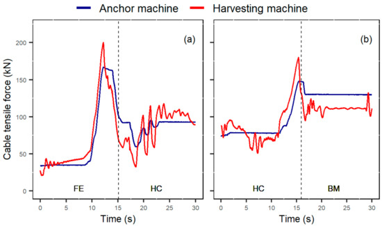
Figure 3.
Example of significant events during stationary work elements: (a) Cable tensile force increment due to downhill-facing felling; (b) Cable tensile force increments due to downhill-facing hoe-chucking, bunching trees for the subsequent yarding operations. BM, other-boom-movements; FE, felling; and HC, hoe-chucking.
3.4. Winch Operations and Tensile Force Implications during Moving-Out and Downhill-Facing Turning
When traveling away from the anchor machine (i.e., moving-out, normally downhill), high cable tensile forces limited the ability of the harvesting machine to turn. Thus, the Summit Winch Assist was designed to switch to cable off the drum when at least one pedal is actuated above the threshold value in the direction away from the anchor machine. With the winch being active, the band brake is off, and actuation of at least one pedal beyond the threshold value will disengage the wet clutch, enable dynamic braking, and permit the cable to be pulled off the drum.
This design frequently led to a limited and short spike in the cable tensile force when the harvesting machine started moving-out, followed by a drop due to the disengagement of the braking system (Figure 4). The initial short spike was likely related to the pedal threshold and communication time lag between the two machines, which led to a shortly delayed opening of the braking system. While the limited spike in the cable tensile forces was particularly evident at the harvesting machine, it was more limited (sometimes almost imperceptible) at the anchor machine. Following this initial spike, the disengagement of the braking system and the consequent pulling of the cable from the drum led to drops of the tensile forces at the anchor machine at about 50 kN (ranging from 25 to 75 kN), which represents a measure of the dynamic braking effect. During the same time, the harvesting machine recorded tensile forces similar or higher.
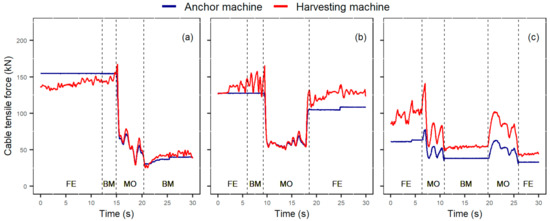
Figure 4.
Example of significant events recorded during moving-out: (a) Typical spike-and-drop in cable tensile forces, followed by stable tensile forces around the dynamic braking; (b) Similar to a, but evidence of tensile force increments in the last moments of moving-out; (c) Evidence of tensile force increments at both the harvesting and anchor machine when the tensile forces at the anchor machine are lower than dynamic braking (note tensile forces after second 19.5). FE, felling; BM, other-boom-movements; and MO, moving-out.
At the end of moving-out, cable tensile forces remained constant around the values recorded during the dynamic breaking (Figure 4a) or increased to higher values (Figure 4b). The different response was most likely linked to the threshold settings in the pedal controls. Minor movements of the harvesting machine at low pedal pressure—below the threshold limit—led to the activation of the winch brake while the harvesting machine was still moving, leading to an increment in the cable tensile forces at the end of moving-out.
A different behaviour was observed when the tensile forces at the anchor machine at the beginning of moving-out were lower than the dynamic braking capacity (about 50 kN). In this case, instead of a spike-and-drop, the cable tensile forces at both the anchor and harvesting machine recorded a positive increment linked to the harvesting machine movements and the pulling of the cable from the drum (Figure 4c).
Very high tensile force increments during moving-out and downhill-facing turning were recorded in three main events. In each of these events the operator was slowly negotiating obstacles, most likely with the pedal pressure unintentionally shifting below and above the set threshold, causing rocking brake activation. This led to the highest peaks recorded in the study, with spikes at the harvesting machine exceeding 250 kN (Figure 5a,b)—reaching the maximum working load recorded in the observation (41.6% of the MBS)—and exceeding the SWL at both the harvesting and anchor machine. Moreover, even though stationary work elements were responsible for the majority of the time exceeding SWL at the harvesting machine, this was mostly linked to limited increments of the high tensile forces due to previous movements of the harvesting machine (moving-out) and their interaction with pedal controls and threshold settings (Figure 5c).
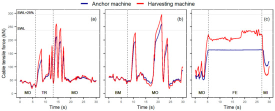
Figure 5.
Example of events exceeding the SWL: (a) Spikes recorded during turning facing downhill and moving-out linked to slow negotiation of obstacles; (b) Similar to a, but exceeding SWL at both the harvesting and anchor machine and approaching SWL + 25% at the harvesting machine; (c) Cable tensile force increments during moving-out and consequent exceedance of SWL during limited increments in stationary work elements.3.2. Winch operations and tensile force implications during moving-in and turning facing uphill. FE, felling; BM, other-boom-movements; MI, moving-in; MO, moving-out; and TR, turning.
3.5. Winch Operations and Tensile Force Implications during Moving-In and Uphill-Facing Turning
When traveling uphill towards the anchor machine (i.e., moving-in), the drive motors of the harvesting machine were on the downhill side of the harvesting machine. Thus, to travel towards the anchor machine the harvesting machine pedals were moved in the forward position. In order to release the brake and engage the winch, the Summit Winch Assist requires both the left and right pedals to be in the forward position. With both the pedals actuated beyond the threshold value in the forward direction, the winch motor was started at the low displacement setting. If hydraulic pressure in the winch drive motor exceeded a threshold value, the winch drive motor was switched to the high displacement setting.
As observed during moving-out, winch design and settings (i.e., pressure threshold settings at both pedals and winch displacement) and the relative movements of the harvesting machine had a direct impact on the observed cable tensile forces during moving-in. The initial low displacement setting of the winch response at the initial moments of moving-in (with the harvesting machine pushing towards the anchor machine) led to two different behaviours, depending on the initial tensile forces at the anchor machine. When the tensile forces at the anchor machine were higher than the pulling capacity of the winch at low displacement settings (which was about 100–110 kN), a drop in the cable tensile forces was recorded at both the anchor and the harvesting machine (Figure 6a). When the initial tensile force at the anchor machine was lower than that of the low displacement mode’s pulling capacity, the harvesting machine still recorded a drop in the cable tensile forces, but the anchor machine recorded a sharp increment (Figure 6b). For either case, as clearly shown in Table 3, the tensile force values recorded during moving-in were generally higher at the anchor machine compared to the harvesting machine.
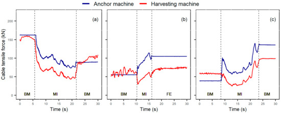
Figure 6.
Example of significant events recorded during moving-in: (a) Drop in cable tensile forces at both the harvesting and anchor machine; (b) Drop in the cable tensile forces at the harvesting machine and increment at the anchor machine; (c) Similar to b, but with evidence of shifting to high displacement in the winch drive motor. FE, felling; BM, other-boom-movements; and MI, moving-in.
The exact moment of switching from low displacement to high displacement mode during moving-in (and its related implications on the tensile forces) is not always easily recognisable in the time series because of the many other factors that can affect local values of cable tensile forces. An example of low to high displacement switching is shown in Figure 6c.
When the harvesting machine was turning uphill towards the anchor machine, the cable tensile forces did not interfere with turning and the winch brake could remain engaged. Thus, when only operating one pedal in the forward direction (i.e., driving one track towards the anchor machine), the winch brake remains engaged and the winch does not turn. Consequently, a drop in the tensile force is expected. Because of the priority system in the time-and-motion study and the fact that the use of one or both pedals over the threshold value is not necessarily detected by the in-cab videos, it has to be noted that in a few cases the observed drops in the cable tensile force during moving-in might also be related to the initial use of a single pedal.
4. Discussion
This study describes the cable tensile forces recorded during winch-assist operations using an anchor machine configuration in a typical, fully-mechanised, steep slope harvesting operation in the PNW. Based on preliminary experience with other systems, the authors upgraded the data collection protocol and successfully provided simultaneous and accurate high-frequency monitoring at both the harvesting and anchor machines. In particular, the improved recording frequency at the anchor machine (from 10 to 100 Hz, equal to the recording frequency at the harvesting machine) and the direct field calibration of the anchor machine represent two key improvements in the procedures recently developed for cable tensile force monitoring of anchor-based winch-assist configurations.
The study also uniquely provides a detailed description of the range of operation for winch systems and the related implications for cable tensile forces, providing a better understanding of the mechanisms behind the observed values. It also provides valuable information about tensile forces, peaks, and exceeding of the safety limits for the observed winch-assist case study, enriching the limited literature. Analysis of local variations in cable tensile forces and other dynamic factors, as provided in other recent publications, was out of the scope of this paper and have not been reported.
The results shown in this work support recent findings about cable tensile forces in active winch-assist harvesting operations. The highest cable tensile force observed was 296 kN, or 41.6% of the MBS of the cable. Peak values recorded for the various work elements are comparable with previous publications, accounting for the different rope sizes and site conditions. Mologni et al. [26], for example, reported peaks up to 48.4% of the MBS, or 400 kN, while monitoring a 28 mm wire rope of a Falcon Winch Assist tethering a feller-director. These peaks, however, were recorded in the most challenging areas of the block. In conditions similar to the current study (Section B, with an average slope of 45% and maximum slope of 72%), the highest working load reported was 41.5% of the MBS. A Summit Winch Assist machine was also monitored by Hunt and Jokai [32]. In their observations on a 40% slope, the highest tensile force (recorded at a frequency of 1 Hz) was 242 kN (34% of the MBS). Other studies on anchor machine configurations reported higher tensile forces, up to 60% of MBS [23].
The Summit Winch Assist system has been designed to use only dynamic braking during downhill movements (moving-out). This typically led to a drop in the tensile force during this work element, which is consistent with observations on other systems that might use a similar approach (e.g., [23,32,43]). However, winch settings, coupled with the slow negotiation of obstacles (at low pedal pressure) contributed to the highest tensile forces in the observed time history. As a result, moving-out has been identified as the most critical work task with respect to cable tensile forces. At a practical level, the results highlight the relevance of careful selection of the machine settings (i.e., lags and thresholds) to avoid these critical peaks. Peaks during moving-out were also the most critical events recorded by several other authors monitoring active winch-assist operations [23,26,27,44].
While cable working load and critical tasks recorded in the present study were comparable to previous publications, the time exceeding SWL was particularly low (0.03% of delay-free productive time). Other publications reported exceeding SWL at least three times more frequently than the current study. Mologni et al. [26], for example, in the less challenging block section (similar to the condition observed in the present study), reported 0.17% of the delay-free productive time over the SWL. Schaare et al. [23] reported between 0.1 and 2.2% of operating time over the SWL. No direct comparison is possible between the various publications because of the many environmental and operational factors affecting the cable tensile forces. However, the solution of using only dynamic braking during moving-out seems to be an effective way to limit unnecessary peaks during downhill movements of the harvesting machine.
Confirmation of recent results have been reported in terms of local differences between the anchor and harvesting machine. While the relative difference in terms of cable tensile forces between the machines is linked to both the observed work tasks and the friction of the cable moving along the ground or around objects, the highest peaks (maximum tensile forces per work element) have always been recorded at the harvesting machine, with differences up to 57 kN. This result is consistent with Mologni et al. [26]. Not only should these findings be carefully considered by practitioners and operators at the operational level, but also by winch manufacturers, the majority of which are currently monitoring cable tensile forces at the anchor machine alone.
In regards to differences in tensile forces between the harvesting and anchor machine, it has to be noted that this study observed both straight pulling and the use of redirecting stumps. The use of redirecting stumps, however, was limited to a short time and the straight pulling frequently involved rub trees (not necessarily detected by the time study observations). While there seemed to be a larger tensile force discrepancy while using redirecting stumps when compared to straight pulling or using rub trees, no statistical analysis or comparison were carried out because of the inappropriate design for this investigation. The use of redirecting stumps and rub trees is a common practice in winch-assist harvesting and further investigation is required to better understand the impact of this practice on cable tensile forces, as suggested by Lyons et al. [34].
Additionally, while this study provides a good example of the impact of winch design and settings on the observed cable tensile forces, there are still major operational factors that need further investigation, including the use of different forest machines (e.g., skidders) and operator skill levels. For a comprehensive understanding of cable tensile forces in winch-assist harvesting, research is also needed for examining the effect of recording frequency in detecting peak values and local variations, as well as the impact of the observed tensile forces on the rope integrity and longevity.
Author Contributions
Conceptualization, O.M., L.M., S.G., R.C., and D.R.; methodology, O.M., C.K.L., E.D.T.N., and D.R.; formal analysis, O.M., C.K.L., and E.D.T.N.; investigation, O.M., C.K.L., and E.D.T.N.; data curation, O.M. and E.D.T.N.; writing—original draft preparation, O.M., C.K.L., and E.D.T.N.; writing—review and editing, O.M., C.K.L., E.D.T.N., L.M., S.G., R.C., and D.R.; visualization, O.M.; supervision, D.R.; project administration, D.R.; funding acquisition, O.M. and D.R. All authors have read and agreed to the published version of the manuscript.
Funding
This research was funded by Mitacs and FPInnovations, through the Mitacs Elevate Program.
Data Availability Statement
The data presented in this study are available on request from the corresponding author. The data are not publicly available due to intellectual proprietary rights of the partner organizations.
Acknowledgments
The authors would like to thank Summit Attachments & Machinery for the support in the study. Thanks are also due to Weyerhaeuser, MVR Timber Cutting, and Robert Jokai for the support in the data collection.
Conflicts of Interest
The authors declare no conflict of interest.
References
- Amishev, D. Winch-Assist Technologies Available to Western Canada; FPInnovations: Vancouver, BC, Canada, 2016; p. 51. [Google Scholar]
- Bennett, N. Timber Supply Crunch Drives Loggers to More Dangerous Terrain. Available online: https://biv.com/article/2016/01/timber-supply-crunch-drives-loggers-more-dangerous (accessed on 21 March 2021).
- FPInnovations. The Evolution of Steep Slope Harvesting in Canada. Available online: https://www.woodbusiness.ca/harvesting/forestry-management/slope-solutions-4053 (accessed on 21 March 2021).
- Garland, J.; Belart, F.; Crawford, R.; Chung, W.; Cushing, T.; Fitzgerald, S.; Green, P.; Kincl, L.; Leshchinsky, B.; Morrissette, B.; et al. Safety in steep slope logging operations. J. Agromedicine 2019, 24, 138–145. [Google Scholar] [CrossRef] [PubMed]
- Mologni, O.; Jokai, R. Cable Tensile Forces in Winch-Assist Harvesting—Assessment of a Falcon Winch Assist Tethering a Feller Director; FPInnovations: Vancouver, BC, Canada, 2020; p. 20. [Google Scholar]
- Cavalli, R. Forest operation in steep terrain. In Proceedings of the CROJFE 2015: Forest Engineering—Current Situation and Future Challenges, Zagreb, Croatia, 18–20 March 2015; p. 3. [Google Scholar]
- Visser, R.; Stampfer, K. Expanding ground-based harvesting onto steep terrain: A review. Croat. J. For. Eng. 2015, 36, 321–331. [Google Scholar]
- Sessions, J.; Leshchinsky, B.; Chung, W.; Boston, K.; Wimer, J. Theoretical stability and traction of steep slope tethered feller-bunchers. For. Sci. 2017, 63, 192–200. [Google Scholar] [CrossRef] [Green Version]
- Belart, F.; Leshchinsky, B.; Sessions, J.; Chung, W.; Green, P.; Wimer, J.; Morrissette, B. Sliding stability of cable-assisted tracked equipment on steep slopes. For. Sci. 2019, 65, 304–311. [Google Scholar] [CrossRef]
- Amishev, D.; Evanson, T. Innovative methods for steep terrain harvesting. In Proceedings of the FORMEC 2010: 43th International Symposium on Forest Mechanization, Padua, Italy, 11–14 July 2010; p. 9. [Google Scholar]
- Holzfeind, T.; Stampfer, K.; Holzleitner, F. Productivity, setup time and costs of a winch-assisted forwarder. J. For. Res. 2018, 23, 196–203. [Google Scholar] [CrossRef]
- Cavalli, R.; Amishev, D. Steep terrain forest operations—challenges, technology development, current implementation, and future opportunities. Int. J. For. Eng. 2019, 30, 175–181. [Google Scholar] [CrossRef]
- Chung, W.; Brennan, G. Tethered logging in Southwest Oregon—Research perspective. In Proceedings of the Western Regional Council on Forest Engineering Conference, Hungary, Austria, 6–10 October 2019. [Google Scholar]
- Leslie, C.; Koszman, C. Productivity and Utilisation of Winch-Assist Machines: Case Studies in New Zealand and Canada; Forest Growers Research: Rotorua, New Zealand, 2019; p. 35. [Google Scholar]
- Holzfeind, T.; Visser, R.; Chung, W.; Holzleitner, F.; Erber, G. Development and benefits of winch-assist harvesting. Curr. For. Rep. 2020, 6, 201–209. [Google Scholar] [CrossRef]
- Dyson, P.; Boswell, B. Winch-Assisted Feller-Buncher Equipped with a Continuous-Rotation Disc Saw: Short-Term Productivity Assessment; FPInnovations: Vancouver, BC, Canada, 2016; p. 17. [Google Scholar]
- Ellegard, J. Finding the perfect steep slope harvesting system. NZ Logger 2015, 6, 21–27. [Google Scholar]
- Amishev, D.; Hunt, J. Winch-Assist Harvester: Best Practice Manual; FPInnovations: Vancouver, BC, Canada, 2018; p. 68. [Google Scholar]
- Donald, K.; Boswell, B.; Amishev, D.; Hunt, J. Winch-Assist Forwarder: Best Practice Manual; FPInnovations: Vancouver, BC, Canada, 2018; p. 68. [Google Scholar]
- Marchi, L.; Grigolato, S.; Mologni, O.; Scotta, R.; Cavalli, R.; Montecchio, L. State of the art on the use of trees as supports and anchors in forest operations. Forests 2018, 9, 17. [Google Scholar] [CrossRef] [Green Version]
- Marchi, L.; Mologni, O.; Trutalli, D.; Scotta, R.; Cavalli, R.; Montecchio, L.; Grigolato, S. Safety assessment of trees used as anchors in cable-supported tree harvesting based on experimental observations. Biosyst. Eng. 2019, 186, 71–82. [Google Scholar] [CrossRef]
- Marchi, L.; Trutalli, D.; Mologni, O.; Gallo, R.; Roeser, D.; Cavalli, R.; Grigolato, S. Mechanical response of natural anchors in cable logging. Int. J. For. Eng. 2020, 1–14. [Google Scholar] [CrossRef]
- Schaare, R.; Harrill, H.; Visser, R. Tension Monitoring of Cable-Assisted Felling Machines; Future Forest Research: Rotorua, New Zealand, 2016; p. 17. [Google Scholar]
- Mancuso, A.; Belart, F.; Leshchinsky, B.; Russell, M.L.; Kiser, J.D. Behavior and assessment of mobile anchors in cable yarding systems. Can. J. For. Res. 2018, 48, 1382–1387. [Google Scholar] [CrossRef]
- Leshchinsky, B.; Sessions, J.; Wimer, J.; Clauson, M. Designing mobile anchors to yield: A tension relief system for tail anchoring. Croat. J. For. Eng. 2016, 37, 269–278. [Google Scholar]
- Mologni, O.; Lyons, C.K.; Marchi, L.; Amishev, D.; Grigolato, S.; Cavalli, R.; Röser, D. Assessment of cable tensile forces in active winch-assist harvesting using an anchor machine configuration. Eur. J. For. Res. 2021. [Google Scholar] [CrossRef]
- Evanson, T.; Amishev, D.; Parker, R.; Harrill, H. An Evaluation of a ClimbMAX Steep Slope Harvester in Maungataniwha Forest, Hawkes Bay; Future Forest Research: Rotorua, New Zealand, 2013; p. 14. [Google Scholar]
- Visser, R. Tension Monitoring of a Cable Assisted Machine; Future Forest Research: Rotorua, New Zealand, 2013; p. 5. [Google Scholar]
- Holzleitner, F.; Kastner, M.; Stampfer, K.; Höller, N.; Kanzian, C. Monitoring tensile forces at cables of winch-assisted harvesters and forwarders in steep terrain cut-to-length harvesting operations. Forests 2018, 9, 13. [Google Scholar] [CrossRef] [Green Version]
- Mologni, O.; Dyson, P.; Amishev, D.; Proto, A.R.; Zimbalatti, G.; Cavalli, R.; Grigolato, S. Tensile force monitoring on large winch-assist forwarders operating in British Columbia. Croat. J. For. Eng. 2018, 39, 193–204. [Google Scholar]
- Holzfeind, T.; Kanzian, C.; Stampfer, K.; Holzleitner, F. Assessing cable tensile forces and machine tilt of winch-assisted forwarders on steep terrain under real working conditions. Croat. J. For. Eng. 2019, 40, 281–296. [Google Scholar] [CrossRef] [Green Version]
- Hunt, J.; Jokai, R. Winch-Assist Tension with the Summit and EMS Systems; FPInnovations: Vancouver, BC, Canada, 2019; p. 10. [Google Scholar]
- Mologni, O.; Jokai, R. Automated data acquisition for cable tension monitoring in winch-assisted harvesting; FPInnovations: Vancouver, BC, Canada, 2019; p. 5. [Google Scholar]
- Lyons, C.K.; Sessions, J.D.; Wimer, J.A. The effect on tether tension when using trees to redirect live machine tethers during forest harvesting on steep slopes. Biosyst. Eng. 2020, 195, 89–96. [Google Scholar] [CrossRef]
- Summit Attachments & Machinery. Winch Assist Operation Manual; Summit Attachments & Machinery: Kelso, WA, USA, 2019; p. 49. [Google Scholar]
- Parker Hannifin. Hydraulic Motors Series V12, V14, T12 Variable Displacement; Parker Hannifin: Trollhättan, Sweden, 2003; p. 68. [Google Scholar]
- TWG-LANTEC. LANTEC Model 540 Hydraulic Planetary Winch; TWG: Jenks, OK, USA, 2009; p. 1. [Google Scholar]
- GMN Bearing. How a Sprag Clutch Works. The Design & Functionality of a One-Way Bearing. Available online: https://www.gmnbt.com/how-sprag-clutches-work/ (accessed on 21 March 2021).
- Winches Inc. Basic Planetary Winch Operation. Available online: https://winchesinc.com/pages/basic-planetary-winch-operation (accessed on 21 March 2021).
- R Core Team. R: A Language and Environment for Statistical Computing; R Core Team: Vienna, Austria, 2021; Available online: https://www.R-project.org/.2021 (accessed on 21 March 2021).
- QGIS Development Team. QGIS Geographic Information System. Open Source Geospatial Foundation Project. 2021. Available online: http://qgis.osgeo.org (accessed on 21 March 2021).
- Wenger, K.F. Logging. In Forestry Handbook; John Wiley & Sons: New York, NY, USA, 1984; pp. 489–564. ISBN 978-0-471-06227-1. [Google Scholar]
- Amishev, D.; Strimbu, V.; Schaare, R. Mechanized Harvesting on Steep Slopes: Short-Term Evaluation of the E.M.S. Tractionline Winch-assist System; FPInnovations: Vancouver, BC, Canada, 2017; p. 22. [Google Scholar]
- Amishev, D.; Dyson, P. Falcon Forestry Equipment (FFE) Winch-Assist Harvesting System; FPInnovations: Vancouver, BC, Canada, 2018; p. 16. [Google Scholar]
Publisher’s Note: MDPI stays neutral with regard to jurisdictional claims in published maps and institutional affiliations. |
© 2021 by the authors. Licensee MDPI, Basel, Switzerland. This article is an open access article distributed under the terms and conditions of the Creative Commons Attribution (CC BY) license (https://creativecommons.org/licenses/by/4.0/).