Abstract
Quantum communication enables high-fidelity image transmission but is vulnerable to channel noise, and while advanced quantum error correction (QEC) can reduce such effects, its complexity and time-domain dependence limit practical efficiency. This paper presents a novel, low-complexity, and noise-resilient quantum image transmission framework that operates in the frequency domain using the quantum Fourier transform (QFT) combined with the three-qubit QEC code. In the proposed system, input images are first source-encoded (JPEG/HEIF) and mapped to quantum states using single-qubit superposition encoding. Three-qubit QEC is then applied for channel protection, effectively safeguarding the encoded data against quantum errors. The channel-encoded quantum data are subsequently transformed via QFT for transmission over noisy quantum channels. At the receiver, the inverse QFT recovers the frequency-domain representation, after which three-qubit error correction, quantum decoding, and corresponding source decoding are performed to reconstruct the image. Results are analyzed using bit error rate (BER), peak signal-to-noise ratio (PSNR), structural similarity index measure (SSIM), and universal quality index (UQI). Experimental results show that the proposed quantum frequency-domain approach achieves up to 4 dB channel SNR gain over equivalent quantum time-domain methods and up to 10 dB over an equivalent-bandwidth classical communication system, regardless of the image format. These findings highlight the practical advantages of integrating QFT-based transmission with lightweight QEC, offering an efficient, scalable, and noise-tolerant solution for future quantum communication networks.
1. Introduction
High-quality image transmission plays an essential role in a wide spectrum of modern applications, including remote sensing, medical diagnostics, surveillance, multimedia broadcasting, and emerging immersive technologies such as virtual and augmented reality [1,2]. In these domains, the ability to transmit images with high fidelity is essential not only for visual quality but also for enabling accurate decision-making in mission-critical scenarios. As imaging and sensing technologies continue to advance, the size, resolution, and complexity of images have increased substantially, leading to a growing demand for transmission systems that can efficiently handle large volumes of data without compromising integrity. However, real-world communication channels are often constrained by bandwidth and affected by channel noise, making it challenging to preserve both the structural integrity and perceptual quality of transmitted images.
To address bandwidth limitations, classical image compression standards such as the joint photographic experts group (JPEG) [3] and the high-efficiency image file format (HEIF) [4] have been widely adopted. These techniques reduce data size by eliminating perceptually redundant information and applying quantization, which significantly decreases storage and transmission requirements. Despite these advantages, compressed image bitstreams are inherently more vulnerable to transmission errors. Even a single bit error in a highly compressed JPEG or HEIF file can result in noticeable artifacts, block distortions, or complete decoding failures, since these formats lack intrinsic error resilience. This vulnerability is particularly problematic in noisy channels, where retransmission-based error recovery can be inefficient or infeasible.
Conventional communication systems have attempted to address these issues through a combination of advanced modulation techniques, channel coding schemes, and retransmission protocols. Error correction codes such as low-density parity check (LDPC) [5], turbo codes [6], and polar codes [7] have achieved impressive error resilience in classical networks, whereas higher-order modulation and adaptive transmission strategies have further improved spectral efficiency. However, these classical solutions are fundamentally limited by Shannon′s channel capacity theorem [8], which defines the maximum achievable data rate for a given bandwidth and signal-to-noise ratio (SNR). For highly compressed image data, achieving an optimal balance between efficiency, reliability, and computational complexity remains a persistent challenge, especially in scenarios with unpredictable or high-noise conditions.
To address these issues, quantum communication [9] offers a fundamentally different approach by exploiting quantum-mechanical principles such as superposition and entanglement [10]. These properties enable enhanced information capacity, new forms of error resilience, efficiency, and theoretically unbreakable security. In the context of image transmission, quantum communication holds promise in achieving high-fidelity delivery under conditions where classical methods struggle. By encoding image data into quantum states, it becomes possible to represent and transmit information in fundamentally different ways, potentially allowing for improved performance in noisy channels.
However, quantum states are inherently fragile. Environmental interactions, imperfect quantum operations, and decoherence can rapidly degrade the transmitted information. This makes quantum error correction (QEC) [11] an indispensable component of any practical quantum communication system. QEC techniques aim to detect and correct errors in quantum states without directly measuring or disturbing encoded information, according to the no-cloning theorem [12], which prohibits the creation of identical copies of unknown quantum states. Several advanced QEC schemes have been developed, including the Shor code [13], Steane code [14], five-qubit codes [15], three-qubit codes [16], surface codes [17], and stabilizer codes [18]. These methods can protect against a variety of quantum noise models, but often require large numbers of ancillary qubits, deep quantum circuits, and complex entanglement operations. This complexity makes them impractical for near-term quantum devices, often referred to as noisy intermediate-scale quantum (NISQ) systems, which have limited qubit counts and short coherence times. The computational and resource overheads also hinder their suitability for real-time applications such as image transmission.
In contrast, the three-qubit QEC method offers the lowest complexity and foundational alternative to protect against bit-flip errors. It encodes one logical qubit into three physical qubits and applies a majority vote decoding strategy to recover from single-bit flips. Although this scheme is limited in its ability to correct multiple errors, its simplicity makes it attractive for early-stage quantum hardware. The three-qubit code has been widely studied in the time domain, where quantum states are processed sequentially over time. However, time-domain operation can be susceptible to cumulative noise effects, as errors introduced early in the transmission may propagate through subsequent operations.
Furthermore, most prior research on quantum image transmission has focused on time-domain encoding schemes, often leveraging quantum superposition for compact representation and entanglement for security. Although these approaches have demonstrated feasibility, they do not fully exploit the advantages of frequency-domain processing in quantum systems. The quantum Fourier transform (QFT) [19], i.e., the quantum analog of the classical discrete Fourier transform (DFT), provides a powerful means of representing quantum states in the frequency domain. QFT offers properties such as spectral distribution of information and phase encoding, which can enhance robustness against certain types of noise and enable more efficient processing for specific applications.
Despite its well-established theoretical advantages, the practical application of the QFT for quantum image transmission remains largely underexplored. To date, only a single study has investigated QFT-based frequency-domain encoding in the context of image transmission [20]. However, to the best of our knowledge, no prior research has integrated QEC with QFT as part of a unified transmission process aimed at improving robustness against quantum channel noise while preserving high image quality. This gap is notable because frequency-domain processing can disperse localized error energy across multiple coefficients, reducing its impact, while lightweight QEC schemes provide protection with minimal qubit resources and low computational overhead. Addressing this gap enables a new research direction that combines the spectral representation power of QFT with low-complexity QEC, yielding a practical, scalable, and noise-resilient quantum image transmission framework for near-term quantum communication systems.
Therefore, we propose a novel quantum communication system for image transmission in the frequency domain, incorporating three-qubit error correction to enable high-quality image delivery over error-prone quantum channels. First, the input images are source-encoded using standard formats such as JPEG and HEIF, with varying quantization parameters (QPs) to generate compressed bitstreams. These bitstreams are then mapped to quantum states, channel-encoded using the three-qubit QEC code for channel protection, and transformed into the frequency domain via the QFT for transmission. Inverse QFT (IQFT) is applied at the receiver to convert the quantum states back to the time domain, followed by quantum channel decoding, quantum state decoding, and final source decoding to reconstruct the transmitted images. The system is evaluated using standard image quality and transmission metrics, including bit error rate (BER), peak signal-to-noise ratio (PSNR), structural similarity index measure (SSIM) [21], and universal quality index (UQI) [22]. Experimental results demonstrate that the proposed frequency-domain quantum system consistently outperforms its time-domain counterpart and equivalent-bandwidth classical communication system in terms of both robustness and reconstructed image quality.
The novel aspects and technical contributions of this study are as follows:
- A novel frequency-domain quantum image transmission framework that integrates QFT with three-qubit QEC, providing enhanced robustness against channel-induced noise.
- Lightweight frequency domain QEC design for image transmission, employing single-qubit superposition encoding and low-complex three-qubit QEC to achieve a practical trade-off between noise resilience, low circuit depth, and minimal qubit overhead.
- Comprehensive comparative analysis of time-domain and frequency-domain quantum image transmission with three-qubit QEC.
The remainder of this paper is organized as follows. Section 2 reviews related work in quantum image transmission, QEC, and frequency-domain quantum processing. Section 3 presents the proposed framework in detail, including the encoding, error correction, and transformation processes. Section 4 describes the experimental setup and evaluation methodology. Section 5 discusses results and performance comparisons, and Section 6 concludes the paper with remarks on future research directions.
2. Related Works
Quantum mechanics [23] provides the fundamental framework for quantum communication and related technologies. Unlike classical communication systems, which encode information in deterministic states, quantum communication systems exploit principles such as superposition [24,25] and entanglement [26,27,28]. These properties enable information to be represented in more expressive ways and manipulated through unitary transformations, making quantum communication fundamentally different from its classical counterparts. Building on these principles, quantum communication applies superposition and entanglement to the reliable transfer of information across noisy or lossy channels. Key milestones in this field include quantum key distribution (QKD), which secures information by exploiting the no-cloning theorem and disturbance from eavesdropping [29], and quantum teleportation, which transmits arbitrary quantum states using shared entanglement and classical communication [30,31]. Over the past two decades, QKD and teleportation have been experimentally demonstrated in fiber, free-space, and even satellite-based links [32,33,34,35,36], establishing them as benchmarks for secure quantum communication. However, their objectives differ from high-fidelity media transmission in noisy quantum channels, which is the focus of this work.
Beyond entanglement-based security protocols, the principle of superposition can be harnessed for high-fidelity quantum image and video transmission. Unlike QKD and teleportation, where the objective is the secure distribution of keys or transfer of arbitrary quantum states, high-fidelity image transmission focuses on the preservation of visual quality under noisy quantum channels. This problem is particularly challenging because image and video data are highly structured and information-rich, making them more sensitive to channel noise, decoherence, and photon loss than single-qubit typically used in QKD experiments.
Early approaches propose time-domain single-qubit encoding and decoding schemes [37,38], which validate the feasibility of transmitting image information over quantum channels. However, these methods demonstrate limited noise resilience and restricted scalability in long-distance or high-loss environments, since each qubit carried only a minimal amount of information. To address these challenges, recent studies have investigated multi-qubit encoding strategies [39] and quantum MIMO frameworks [40,41], exploiting parallelism and spatial diversity. While some efforts have integrated classical error correction codes, such as polar codes, their effectiveness in noise resilience remains limited. Moreover, existing studies do not fully leverage the potential of QEC for robust noise mitigation, nor do they adequately consider scalability to high-resolution images and video streams, where error accumulation becomes increasingly significant. In addition, prior work has been restricted to the time domain, with no exploration of frequency-domain encoding techniques that could improve fidelity by distributing information across multiple basis states.
To address channel-induced errors, QEC has long been regarded as essential. Foundational schemes demonstrate that a single logical qubit could be preserved by distributing its information across multiple physical qubits, thereby mitigating decoherence and noise. Examples include the Shor code [13], which encodes one logical qubit into nine physical qubits, and the Steane code [14], which achieves similar protection with seven qubits. Building on these, numerous other codes have been introduced, such as the three-qubit code [16], the five-qubit code [42], the surface code [43], and various stabilizer codes [44,45].
Among these, the three-qubit QEC code is the simplest and most fundamental, offering the ability to detect and correct a single bit-flip error with minimal resource requirements. Its theoretical underpinnings have been studied extensively in quantum computation [46,47], but its application in quantum communication, particularly for image transmission, has received limited attention [48]. For video transmission, some studies have investigated three, five, and seven-qubit codes in the time domain [49]. However, to the best of our knowledge, no prior research has explored the integration of the three-qubit QEC code with quantum frequency-domain transmission methods, leaving a significant gap for high-fidelity multimedia communication in noisy quantum channels.
This gap motivates a closer look at the quantum frequency domain, a representation of quantum information analogous to the frequency domain in classical signal processing. In classical systems, transforming a signal into the frequency domain using tools such as the Fourier transform allows its components to be analyzed and manipulated based on their spectral characteristics, often enabling more efficient compression, filtering, and noise mitigation. In the quantum setting, the quantum frequency domain refers to a basis in which the amplitudes of quantum states are represented in terms of their spectral components rather than their original computational (time-domain) basis. Accessing this domain requires a unitary transformation, most commonly performed by QFT [50]. By mapping a quantum state into its frequency-domain representation, the information is spread across multiple spectral bins, potentially reducing the impact of localized noise or channel errors on any single portion of the data.
However, existing uses of QFT in quantum information processing have largely focused on algorithmic subroutines or single-task signal processing operations such as quantum data compression, phase estimation, and spectral analysis [51,52,53]. These applications typically treat QFT as a supporting component within a larger quantum algorithm rather than as the core encoding mechanism for transmitting data. In addition, several studies have utilized QFT in QKD [54] and in teleportation protocols [55,56,57] to address security aspects. In the context of quantum image transmission, only one known study has employed QFT as a direct encoding scheme for transmitting images over a quantum channel, and even that work did not explore integrating QFT with QEC to enhance noise resilience [20].
Therefore, this study introduces a novel quantum frequency-domain encoding framework that integrates a three-qubit QEC code for high-quality image transmission. Unlike previous approaches, in which QFT has been used solely as a direct encoding method and QEC applied only in time-domain transmission, the proposed method unifies these two techniques into a single coherent framework. In the proposed approach, quantum states are first encoded with the three-qubit QEC to protect against bit-flip errors, and the resulting error-protected states are subsequently transformed into the frequency domain using the QFT. This integration leverages the inherent benefits of spectral-domain processing, such as dispersing localized errors and improving robustness, before transmission over noisy quantum channels. To the best of our knowledge, this is the first work to combine three-qubit QEC with frequency-domain quantum encoding specifically for image transmission applications. Beyond improving resilience in noisy channels, the proposed method can potentially be extended to other quantum media delivery tasks, integrated into hybrid quantum–classical communication networks, and adapted for near-term NISQ devices where both resource efficiency and noise tolerance are critical.
3. Methodology
The general end-to-end communication framework of the proposed system is illustrated in Figure 1. The design is flexible and capable of processing any input image, regardless of its resolution, color format, file format (e.g., JPEG, HEIF), or level of compression, making it suitable for a wide variety of image sources and applications. The process begins with source encoding of the image, followed by quantum state preparation, channel encoding, and transformation into the frequency domain. The encoded data are then transmitted over a noisy quantum channel. At the receiver, the process begins with the application of the IQFT to convert the data back to the time domain, followed by quantum channel decoding, quantum state decoding, and the corresponding source decoding to reconstruct the original image. In particular, each stage of this pipeline is carefully designed to balance noise resilience, computational efficiency, and compatibility with near-term quantum hardware. The detailed operation of each main block in the framework is described in the following subsections.
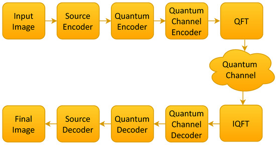
Figure 1.
The proposed frequency domain quantum communication system with QEC.
3.1. Source Encoder and Decoder
Each image is first compressed using JPEG or HEIF, where transform coding is performed using either the discrete cosine transform (DCT) in JPEG or high-efficiency video coding (HEVC) intra-prediction in HEIF. This step is followed by quantization at quality levels Q25, Q50, Q75, and Q100. Lower quantization levels (e.g., Q25) produce coarser representations by discarding more high-frequency components, resulting in smaller bitstreams but reduced fidelity. Conversely, higher levels (e.g., Q100) retain most transform coefficients, yielding larger bitstreams with higher reconstruction quality.
3.2. Quantum Encoder
The purpose of the quantum encoder is to transform the source-encoded image bitstream into quantum states that can be later exploited by the principles of quantum superposition.
First, each source bit is mapped to its corresponding computational basis state, as shown in Equations (1) and (2).
This initializes qubits in the computational basis, with no probability amplitude spread across multiple states.
In practice, to achieve this, all qubits are initialized to the ground state , and for each bit , a Pauli-X gate [58] is applied to flip the qubit to , while bits with leave the qubit unchanged.
Second, quantum superposition is introduced by applying the Hadamard operator H [59], defined in Equation (3).
Its action on the computational basis transforms and into the superposition states and , as shown in Equations (4) and (5).
The Hadamard gate is first applied to transform the computational basis states into equal superposition states, thereby distributing information across both amplitude and phase domains. This superposition is fundamental to QEC and continues to play a vital role in the subsequent stages of the communication process, supporting the efficient utilization of quantum resources.
3.3. Quantum Channel Encoder and Decoder
After quantum bit mapping and the creation of superposition states, the qubits pass through a quantum channel encoding stage designed to protect them from transmission errors, as shown in Figure 2. The three-qubit QEC code is selected as a lightweight and representative model to illustrate the central contribution of this work: the integration of frequency-domain processing via the QFT into quantum communication. While more advanced codes (e.g., Steane, Shor, or surface codes) provide stronger protection, they also introduce high circuit depth and resource overhead, making them impractical for NISQ-era implementations. In contrast, the three-qubit code offers low complexity and shallow depth [60,61,62], ensuring that observed performance improvements can be directly attributed to the frequency-domain encoding rather than the strength of the QEC scheme itself. Thus, the chosen code provides a practical balance between simplicity, demonstrative clarity, and near-term feasibility, while the framework remains extendable to more advanced codes in future work.
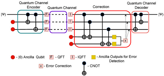
Figure 2.
Quantum circuit for the three-qubit QEC encoder and decoder.
3.3.1. Three-Qubit State Preparation
Let the initial quantum state be denoted by , which can be expressed as shown in Equation (6). This state represents the quantum-encoded superposition states corresponding to the or basis states.
This state, which is already in a superposition due to the preceding Hadamard operation, is augmented by introducing two additional ancillary qubits, both prepared in the state. This results in a composite three-qubit state, as shown in Equation (7).
This transition from a single-qubit superposition to a three-qubit configuration highlights the motivation for redundancy: while a superposition allows quantum parallelism, it is inherently fragile under noise. By distributing the logical qubit across multiple physical qubits, the system gains protection against errors that may arise during transmission. This redundancy is the cornerstone of quantum error correction, ensuring that quantum information is not irreversibly lost to the environment.
3.3.2. Applying CNOT Gates
To establish correlations between qubits, the controlled-NOT (CNOT) gates are applied in a specific sequence. The first qubit acts as the control, targeting the second qubit in the first CNOT operation. The same control qubit is then used to target the third qubit in a second CNOT operation.
Mathematically, the CNOT gate applies an X (bit-flip) operation to the target qubit only when the control qubit is in the state. This behavior can be expressed as shown in Equation (8).
Therefore, applying both CNOT gates transforms the state in Equation (7) into the state shown in Equation (9).
This transformation effectively creates entanglement between the qubits, ensuring that any bit-flip error affecting one qubit can be detected and potentially corrected.
In intuitive terms, the two CNOT gates act to “spread” the logical information of the first qubit across all three qubits. If the first qubit is in the state, the ancillary qubits remain unchanged, producing . If the first qubit is in the state, both targets are flipped, resulting in . Because the input is a superposition, the output is an entangled superposition of these possibilities. This process is often referred to as the three-qubit repetition code, where redundancy is introduced not by duplicating the qubit, but by establishing strong correlations among the qubits. Such correlations form the foundation of quantum error correction, ensuring that the encoded information can survive the disturbance of a noisy channel.
3.3.3. Impact of Noisy Channels
When this encoded state propagates through a quantum channel, it may encounter bit-flip, phase-flip, or combined errors due to environmental interactions. For example, a single bit-flip in the first qubit can change to or vice versa. Since the encoding spreads the logical information over three qubits, the system is resilient to single-qubit errors, provided that they can be identified.
3.3.4. Error Detection and Error Correction
To detect such errors, two additional ancilla qubits are appended, each initialized to , as shown in Figure 2. These ancillas interact with the data qubits through additional CNOT gates, allowing the error information (syndrome) to be imprinted on them. The ancilla qubits serve as noninvasive ‘error flags′. Importantly, they do not carry logical information themselves; instead, they serve as diagnostic tools that indirectly reveal which qubit, if any, has been corrupted. Because the interaction is carefully designed, the ancilla measurement does not disturb the logical state but merely extracts the error syndrome.
The resulting ancilla state after this interaction depends on the error pattern, as summarized in Table 1.

Table 1.
Mapping between received quantum states, error locations, and corresponding ancilla measurements.
Each syndrome output (ancilla output) corresponds to a specific corrective operation, typically a Pauli-X gate applied to the erroneous qubit, as summarized in Table 2. In practice, this means that the ancillas serve as diagnostic markers: their measurement indicates exactly which qubit has been affected by an error and prescribes the appropriate recovery step. By following this mapping, the system can restore the encoded state to a valid form, ensuring that the original quantum information remains intact despite the presence of noise.

Table 2.
Syndrome actions and corresponding corrective operations.
3.3.5. Three-Qubit Decoder
Decoding reverses the encoding process. The two CNOT gates from the encoding stage are applied in reverse order: first between the first and third qubits, then between the first and second qubits. This process disentangles the qubits and restores the logical qubit to its original form, as in Equation (7). The additional ancilla qubits, having served their role in detecting errors, collapse deterministically to and can be safely discarded, leaving only the recovered quantum superposition state.
3.4. Quantum Decoder
After the three-qubit quantum decoding processes, the resulting noisy superposition states of the qubits are directed to the quantum measurement stage. At this stage, projective measurement operators are applied to retrieve the classical bit values from the received superposition states. Once measurement is performed, the post-measurement quantum state is obtained by normalizing the projected state, as expressed in Equation (10).
In this expression, denotes the measurement operators, for example, and , which project a qubit state onto the corresponding computational basis state, with representing the adjoint of . The decoding procedure can be illustrated using , as shown in Equation (11).
The same procedure with can be applied to extract the corresponding information for the state. Using this method, the corresponding classical bits can be extracted.
3.5. Transmission Process
After the three-qubit channel-encoded states are prepared, they are mapped from the time-domain representation into the frequency-domain representation using the QFT.
3.5.1. QFT
The QFT is the quantum analog of the classical DFT, acting on the amplitudes of quantum states in a reversible and unitary manner.
The QFT is then defined as the transformation shown in Equation (13).
where is a computational basis state and are the basis states in the frequency domain. The exponential term introduces a phase shift proportional to the product of the input and output indices, and the factor ensures unitarity.
From Equation (13), the general QFT matrix of size can be expressed as Equation (14).
where is the primitive root of unity.
For three-qubit-encoded states, where qubits are used and , the QFT is represented by the matrix given in Equation (15).
where
When QFT () is applied to the quantum-encoded state of three qubits, the result is given by Equation (16).
Due to the unique properties of the QFT matrix, the application of the QFT to each computational basis state produces the corresponding unique column of the QFT matrix. This correspondence is determined by the value of the quantum state: if the basis state is , the output is the first column of ; if it is , the output is the second column of ; if it is , the output is the third column, and so on. This property can be verified directly through matrix multiplication, as demonstrated in Equations (17) and (18).
Using this mapping, the state in Equation (16) can be represented in the frequency domain and transmitted through the quantum channel. However, this transformation does not directly benefit the error-correction process, because after transmission, the inverse QFT must be applied before error correction. Nevertheless, representing the state in the frequency domain can offer advantages during the transmission process itself, such as improved efficiency and error resilience by leveraging the inherent benefits of the frequency domain.
3.5.2. IQFT
The IQFT is the inverse operation of the QFT and is used to map quantum states from the frequency domain back to the time domain. Mathematically, the IQFT is expressed in Equation (19) and is identical to the QFT, except that the sign of the exponent is reversed.
Since the QFT is a unitary transformation, its inverse is given by Equation (20).
where denotes the conjugate transpose of .
For an n-qubit system (), the IQFT matrix is obtained by taking the Hermitian adjoint of , which involves transposing the matrix and replacing each root of unity with its complex conjugate . Therefore, applying the IQFT to the received frequency-domain state after transmission restores it to the time-domain representation, enabling subsequent quantum error correction.
3.5.3. Quantum Channel
To emulate realistic quantum communication conditions, the proposed system is tested under the following types of quantum noise [62]. Five canonical noise channels are considered: bit-flip, phase-flip, depolarizing, amplitude damping, and phase damping. Each channel is parameterized by a probability value that controls the likelihood of the corresponding error process. Hardware imperfections are not modeled in this study, as these general noise models are commonly used to evaluate the performance of an early-stage quantum communication system.
The overall effect of noise is represented using a composite quantum channel, which combines all error processes into a single probabilistic model, as defined in Equation (21) [20].
where and denote the respective error probabilities. These probabilities are adjusted according to the SNR to simulate different channel conditions, with the signal power normalized and the noise power varied across simulations.
This total noise probability is then distributed among five types of quantum noise: bit-flip (), phase-flip (), depolarizing (), amplitude damping (), and phase damping (). To assign these probabilities dynamically and non-deterministically, five independent random values are generated, as shown in Equation (22), which act as weighting coefficients.
These values are normalized and scaled to ensure that each noise type receives a proportion of the total noise, as shown in Equation (23).
This assignment satisfies the total noise constraint in Equation (24).
The corresponding individual noise channels are modeled according to Equations (25)–(29). In all these equations, represents the density matrix of the quantum state; and Z denote the Pauli operators; and the symbol †; indicates the conjugate transpose (Hermitian adjoint).
- Bit-flip channel (X-noise):
- Phase-flip channel (Z-noise):
- Depolarizing channel:
- Amplitude damping channel:
- Phase damping channel:
These noise models correspond to realistic error sources encountered in optical, superconducting, and ion-trap platforms. Rather than assuming a single dominant error process, the adopted probabilistic mixing strategy captures the heterogeneous nature of practical quantum communication environments. In addition, the SNR mapping links channel quality to error dynamics by inversely scaling the total noise probability with SNR and allocating it stochastically across the five noise types. Although simplified, this abstraction achieves a balance between physical realism and analytical tractability, making it a robust framework for benchmarking quantum communication systems under diverse channel conditions.
4. Experimental Setup
In this evaluation, 100 images are randomly selected from the Microsoft COCO dataset [63], ensuring a broad range of real-world content with diverse textures, object densities, and color distributions. Such diversity guarantees that the test set contains images with varying spatial complexity and structural characteristics.
Each image is pre-processed using two widely adopted source coding standards: JPEG, which applies the DCT to represent image data in the frequency domain for efficient lossy compression [3], and HEIF, which is based on the HEVC standard and achieves higher compression efficiency through advanced block-based prediction and transform coding [4]. Four QP values are evaluated, , covering a range from low visual quality (high compression) to high visual quality (low compression).
The complete process for each configuration is simulated entirely in Python 3 using a modeled program derived from the mathematical framework of the proposed quantum communication system and the time-domain quantum baseline. A generalized quantum noise model is applied to emulate channel impairments, and all encoding, decoding, and transformation operations (including QFT/IQFT when applicable) are executed through software simulation rather than hardware implementation. Furthermore, all experiments are conducted on a computing system equipped with an Intel Core i5-1345U CPU (1.60 GHz, Intel Corporation, Santa Clara, CA, USA) and 16 GB of RAM. For each of the 100 images, 1000 independent trials are conducted under each test image to reduce random variability and obtain statistically reliable results, and the average values are reported.
To provide further clarity in implementation, we detail the intermediate processing pipeline step by step. Each input image is first source-coded with different QP values and converted to a binary bitstream. These bitstreams are mapped into quantum states through basis preparation, followed by superposition via Hadamard gates, and subsequently protected using the three-qubit QEC code. Since the system operates in the frequency domain, a QFT is applied after encoding and before transmission. Noise is introduced according to the generalized quantum noise models adopted in order to emulate realistic transmission impairments during the transmission process. On the receiver, an inverse sequence of operations is performed, including IQFT, QEC decoding, basis measurement, and reassembly of the recovered image data. This step-by-step specification bridges the theoretical blocks presented in Figure 1 with their explicit operational roles, ensuring that the system description captures not only the conceptual design but also the practical simulation workflow. Furthermore, a time-domain system is modeled using the same architecture, excluding the QFT and IQFT operations. In addition, a classical communication system is implemented using binary phase-shift keying (BPSK) modulation and polar codes with a 1/3 code rate, with bandwidth matched to that of the proposed system for comparison.
5. Results and Discussion
This section presents a detailed performance evaluation of the proposed system using four key metrics: BER, PSNR, SSIM, and UQI. The results are analyzed to highlight performance trends, with particular attention to how compression format and quality affect error resilience and visual fidelity. In addition, the discussion emphasizes the trade-offs observed between compression efficiency and reconstructed image quality across the tested scenarios.
5.1. Comparative Analysis of Quantum Frequency-Domain, Quantum Time-Domain, and Classical Schemes for JPEG Image Transmission
Performance comparison between Q-Frequency (quantum three-qubit error correction with transmission in the frequency domain), Q-Time (quantum three-qubit error correction with transmission in the time domain), and C-Polar (classical communication system with polar codes at a code rate of 1/3), as illustrated in Figure 3, reveals a consistent performance across all tested QP values of 25, 50, 75, and 100 for JPEG images. In every case, Q-Frequency achieves the lowest BER, indicating superior robustness to channel noise. While Q-Time exhibits higher BER than Q-Frequency, it still maintains a clear advantage over the classical polar-coded system (C-Polar) in error resilience. The C-Polar scheme generally exhibits the highest BER, especially at low SNR. The stability of relative performance across varying QP values indicates that BER is primarily influenced by the underlying transmission domain and communication method, rather than the applied image compression level. The results highlight a distinct frequency-domain advantage relative to the time-domain approach, with both quantum-domain schemes exhibiting superior performance compared to the classical communication system.
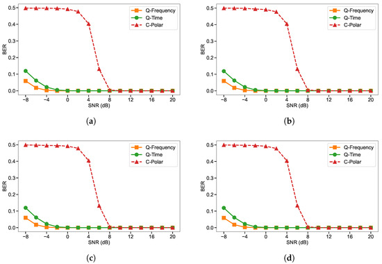
Figure 3.
BER comparison of the three-qubit quantum frequency-domain system (Q-Frequency), the three-qubit quantum time-domain system (Q-Time), and the polar-coded classical system (C-Polar), evaluated under identical bandwidth and channel conditions using JPEG compression: (a) Q25, (b) Q50, (c) Q75, and (d) Q100.
A similar performance trend is observed when evaluating image quality in terms of PSNR for JPEG images at QP values of 25, 50, 75, and 100, as shown in Figure 4. Across all compression levels, Q-Frequency consistently achieves the highest PSNR, with a clear performance gain over Q-Time. In many cases, this SNR gain reaches 3–4 dB at low-to-moderate SNR values, representing a substantial improvement in perceived image quality compared to Q-Time. This advantage reflects the effectiveness of quantum frequency-domain transmission in mitigating noise-induced distortions compared to the quantum time-domain approach. Q-Time follows as the second-best performer, whereas C-Polar yields the lowest PSNR, particularly at low SNR values. Across all QP values, the gap between Q-Frequency and Q-Time remains largely unchanged. However, the performance of the classical communication system lags behind, with an approximate 8 dB deficit in channel SNR compared to the Q-Time.
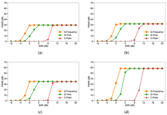
Figure 4.
PSNR comparison of the three-qubit quantum frequency-domain system (Q-Frequency), the three-qubit quantum time-domain system (Q-Time), and the polar-coded classical system (C-Polar), evaluated under identical bandwidth and channel conditions using JPEG compression: (a) Q25, (b) Q50, (c) Q75, and (d) Q100.
When SSIM is considered, the performance trend for JPEG images at QP values of 25, 50, 75, and 100, as shown in Figure 5, mirrors the PSNR results, with Q-Frequency consistently outperforming the other schemes. Across all compression levels, Q-Frequency achieves SSIM values that are significantly higher than Q-Time at low-to-moderate SNR, representing a notable improvement in the preservation of perceptual image quality. This advantage is especially evident at lower SNR values, where frequency-domain encoding helps maintain structural details more effectively than the time-domain approach. Q-Time consistently ranks second, while C-Polar produces the lowest SSIM, particularly under noisy conditions.
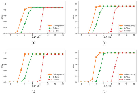
Figure 5.
SSIM comparison of the three-qubit quantum frequency-domain system (Q-Frequency), the three-qubit quantum time-domain system (Q-Time), and the polar-coded classical system (C-Polar), evaluated under identical bandwidth and channel conditions using JPEG compression: (a) Q25, (b) Q50, (c) Q75, and (d) Q100.
For the UQI, the results for JPEG images at QP values of 25, 50, 75, and 100, as shown in Figure 6, show the same consistent ranking as the other metrics, with Q-Frequency outperforming Q-Time and C-Polar across all SNR levels. The Q-Frequency outperforms Q-Time at low-to-moderate SNR values, reflecting its stronger ability to preserve both luminance and contrast information during transmission over noisy channels. This advantage is most prominent under lower SNR conditions, where frequency-domain encoding helps mitigate the effects of noise on structural and contrast fidelity.
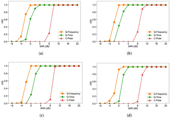
Figure 6.
UQI comparison of the three-qubit quantum frequency-domain system (Q-Frequency), the three-qubit quantum time-domain system (Q-Time), and the polar-coded classical system (C-Polar), evaluated under identical bandwidth and channel conditions using JPEG compression: (a) Q25, (b) Q50, (c) Q75, and (d) Q100.
The consistent superiority of Q-Frequency over Q-Time across all evaluated metrics arises from the enhanced robustness provided by its frequency-domain representation. In Q-Frequency, the quantum three-qubit channel-encoded bitstream is transformed into the frequency domain, where each qubit is represented as a superposition of multiple basis states with additional phase encoding. This combination not only distributes the energy of the signal across spectral components but also embeds additional phase information that improves resilience to both amplitude and phase distortions introduced by channel noise. The spectral redundancy and phase diversity allow for the partial recovery of degraded components during the inverse transform, reducing the impact of localized frequency losses.
In contrast, Q-Time transmits the quantum channel-encoded bitstream directly in the time domain, without the benefits of frequency-domain processing, which combines superposition and phase encoding. As a result, instantaneous noise fluctuations translate more directly into pixel-level errors, limiting the recovery potential. Although both schemes benefit from three-qubit QEC, the combination of frequency-domain mapping in the Q-Frequency scheme explains its consistently better BER, PSNR, SSIM, and UQI results, particularly at low-to-moderate SNR levels where noise effects are most pronounced.
5.2. Comparative Analysis of Quantum Frequency-Domain, Quantum Time-Domain, and Classical Schemes for HEIF Image Transmission
For HEIF images at QP values of 25, 50, 75, and 100, the BER results follow the same consistent performance ordering observed in the JPEG experiments, as shown in Figure 7. Across all compression levels, Q-Frequency delivers the lowest BER, followed by Q-Time, with C-Polar performing worst at low SNR. The performance advantage of Q-Frequency over Q-Time is evident across the entire SNR range, particularly at low-to-moderate SNR values where the spectral redundancy and phase diversity of the frequency-domain approach help mitigate noise-induced errors more effectively. The similarity in trends between HEIF and JPEG results suggests that the observed performance hierarchy is robust to changes in source image format, with Q-Frequency consistently providing the highest noise resilience regardless of compression level or image coding standard.
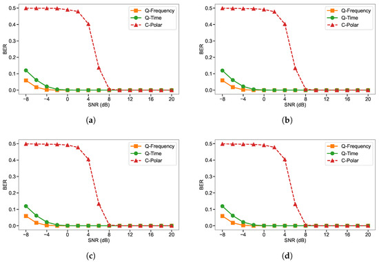
Figure 7.
BER comparison of the three-qubit quantum frequency-domain system (Q-Frequency), the three-qubit quantum time-domain system (Q-Time), and the polar-coded classical system (C-Polar), evaluated under identical bandwidth and channel conditions using HEIF compression: (a) Q25, (b) Q50, (c) Q75, and (d) Q100.
As shown in Figure 8, the evaluation of HEIF images in terms of PSNR at QP values of 25, 50, 75, and 100 reveals the same consistent performance hierarchy previously observed for JPEG images. Q-Frequency achieves the highest PSNR across all compression levels, with a clear gain over Q-Time. This improvement reflects the benefits of combining frequency-domain transmission, which incorporates superposition along with additional phase encoding, with QEC, thereby enhancing resistance to both amplitude and phase distortions. In addition, the advanced source coding efficiency of HEIF results in a higher maximum PSNR compared to JPEG. This improvement is primarily due to HEIF′s use of modern compression tools, such as more efficient intra-prediction, improved transform coding, and advanced entropy coding, which collectively reduce quantization errors and preserve more image detail at a given bitrate.
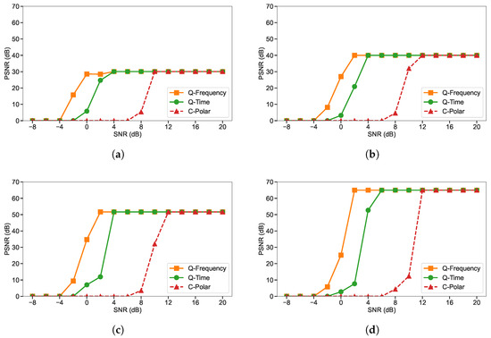
Figure 8.
PSNR comparison of the three-qubit quantum frequency-domain system (Q-Frequency), the three-qubit quantum time-domain system (Q-Time), and the polar-coded classical system (C-Polar), evaluated under identical bandwidth and channel conditions using HEIF compression: (a) Q25, (b) Q50, (c) Q75, and (d) Q100.
At QP values of 25, 50, 75, and 100, the SSIM results for HEIF images, as shown in Figure 9, follow the same performance hierarchy observed for JPEG images, with Q-Frequency consistently attaining the highest values and retaining a clear margin over Q-Time at low to moderate SNR levels. Similarly, the UQI results, as shown in Figure 10, mirror the trends from the JPEG experiments. Q-Frequency outperforms Q-Time with an approximate maximum channel SNR gain of 4 dB. Q-Time ranks second, while C-Polar records the lowest UQI, particularly in low-SNR scenarios.
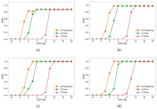
Figure 9.
SSIM comparison of the three-qubit quantum frequency-domain system (Q-Frequency), the three-qubit quantum time-domain system (Q-Time), and the polar-coded classical system (C-Polar), evaluated under identical bandwidth and channel conditions using HEIF compression : (a) Q25, (b) Q50, (c) Q75, and (d) Q100.
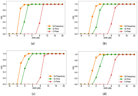
Figure 10.
UQI comparison of the three-qubit quantum frequency-domain system (Q-Frequency), the three-qubit quantum time-domain system (Q-Time), and the polar-coded classical system (C-Polar), evaluated under identical bandwidth and channel conditions using HEIF compression: (a) Q25, (b) Q50, (c) Q75, and (d) Q100.
5.3. Comprehensive Performance Analysis: Objective Metrics and Subjective Assessments
Based on the BER, PSNR, SSIM, and UQI results for both JPEG and HEIF images across QP values of 25, 50, 75, and 100, the performance of the proposed system is shown to be largely independent of the image format and compression level. In all tested scenarios, Q-frequency consistently outperforms Q-time and the classical C-Polar scheme. This superiority stems from the dual encoding mechanism of Q-Frequency, in which superposition is combined with phase encoding in the frequency domain. The incorporation of the QFT in our framework enhances robustness to localized errors by enabling efficient frequency-domain encoding. By transforming computational basis states into distributed frequency components, the QFT disperses the effect of localized bit-flip or phase-flip errors across the entire spectrum, reducing their concentration on any single qubit. This dispersion is particularly beneficial under independent error models such as depolarizing and dephasing noise, where error energy becomes less dominant after spreading into phase rotations across multiple amplitudes. While correlated noise channels limit the QFT′s ability to fully decorrelate multi-qubit disturbances, the frequency-domain representation still provides resilience through interference effects and redundancy inherent in phase encoding. The results show that Q-Frequency delivers next-level efficiency and performance compared to the time-domain method, achieving higher fidelity and structural preservation regardless of source format or QP setting. These findings confirm that the choice of transmission domain and quantum encoding strategy has a greater impact on overall system robustness than variations in image coding parameters. However, the Q-Time domain scheme already outperforms the classical communication system under equal bandwidth conditions, demonstrating the superiority of quantum communication over its classical counterpart.
As a representative example to illustrate the visual differences, Figure 11 presents sample decoded images obtained from the Q-Frequency and Q-Time schemes for JPEG inputs with QP 25 and QP 100 at an SNR of 2 dB. The reconstructed images from the Q-Frequency approach consistently demonstrate superior visual quality compared to those obtained from the time-domain method. These perceptual differences correspond to the measured trends in PSNR, SSIM and UQI, confirming that the higher objective scores of Q-Frequency are manifested in observable improvements in the quality of the reconstructed image.
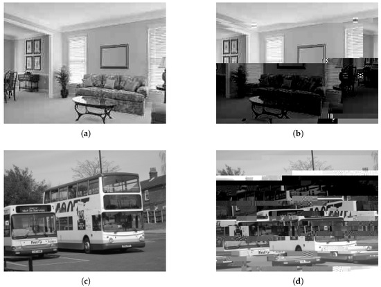
Figure 11.
Sample decoded images for JPEG inputs with QP values of 25 and 100, comparing the Q-Frequency and Q-Time transmission systems at an SNR of 2 dB: (a) Q-Frequency QP 25, (b) Q-Time QP 25, (c) Q-Frequency QP 100, and (d) Q-Time QP 100.
In addition, a subjective visual quality assessment is carried out following the double stimulus procedure [64], with 80 participants of varying age from 15 to 60 years. The evaluation considered JPEG image transmission at QP values of 25 and 100 for both frequency-domain and time-domain configurations as a representative example. For each SNR level, the images generated by the quantum systems are presented to the participants, who rated their visual quality using the mean opinion score (MOS) scale of 0 to 100, where 0 to 20 indicates ‘bad′, 21 to 40 ‘poor′, 41 to 60 ‘fair′, 61 to 80 ‘good′ and 81 to 100 ‘excellent′. The final MOS for each configuration are calculated as the average score across all participants. The results, shown in Figure 12 and Figure 13, closely follow the trends observed in objective quality metrics (PSNR, SSIM, UQI), confirming that the frequency domain approach not only achieves higher numerical scores, but also delivers perceptually superior image quality.
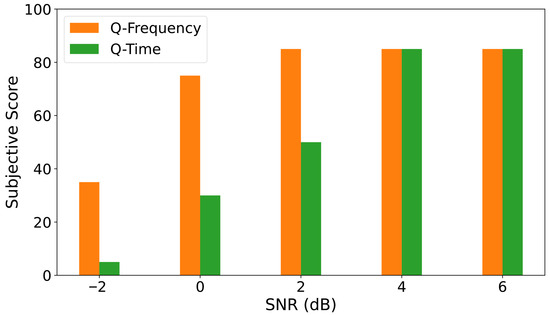
Figure 12.
Subjective quality assessment results for JPEG image transmission using frequency-domain (Q-Frequency) and time-domain systems (Q-Time) at QP 25.
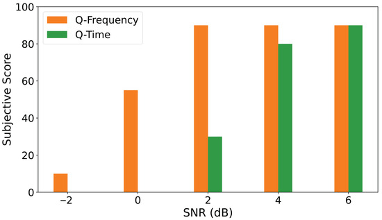
Figure 13.
Subjective quality assessment results for JPEG image transmission using frequency-domain (Q-Frequency) and time-domain systems (Q-Time) at QP 100.
5.4. Computational Cost and Scalability of the Proposed System
In terms of complexity, both Q-Frequency and Q-Time rely on a three-qubit QEC framework; however, Q-Frequency introduces an additional frequency-domain transformation stage through the QFT. This alters the complexity scaling behavior from in the time-domain case to for Q-Frequency, since the QFT requires gates with circuit depth n, compared to n gates and a depth of 1 for the time-domain approach. In the specific setting considered here with , Q-Frequency requires six gates and a depth of three, while the time-domain system needs only three gates with depth one.
Although this analysis highlights that the QFT circuit is inherently more demanding than its time-domain counterpart, the increase in overhead remains modest due to the deliberate choice of small encoding blocks. The use of three-qubit registers ensures that the quadratic scaling does not translate into prohibitive complexity, making the scheme well within the capabilities of near-term quantum devices. Furthermore, the controlled-rotation gates required for QFT are already supported by leading hardware platforms such as superconducting and photonic systems, and the shallow circuit depth minimizes vulnerability to decoherence, ensuring compatibility with NISQ constraints.
Beyond practical implementability, the inclusion of the frequency-domain stage provides a significant advantage. Unlike the time-domain approach, which conveys information only through qubit population states, Q-Frequency exploits both amplitude and phase degrees of freedom. This enhanced representation improves robustness against channel noise and contributes to better preservation of image fidelity, as reflected in metrics such as PSNR, SSIM, and UQI. Thus, while Q-Frequency introduces additional circuit resources compared to Q-Time, the trade-off is favorable: a moderate increase in gate count and circuit depth yields significant improvements in resilience and quality of reconstructed images.
Finally, the proposed framework represents the lowest-complexity frequency-domain transmission scheme with integrated error correction. This is achieved by combining two of the simplest available primitives, single-qubit superposition encoding and the three-qubit QEC code, while limiting the QFT/IQFT to lightweight transforms applied once per transmission cycle. In this way, the design balances theoretical rigor with practical feasibility, ensuring that the benefits of frequency-domain encoding can be realized without imposing prohibitive overhead.
The framework also remains scalable, as higher-order QEC codes with 5, 7, or 9 qubits can be supported without altering the asymptotic complexity, although the runtime and gate overhead increase proportionally with qubit count. Importantly, the modular design of the system allows the QFT/IQFT stage to operate independently of the specific QEC code employed, which means that the same encoder, channel, and decoder pipeline can be maintained as hardware resources grow. In practice, this ensures that improvements in quantum hardware or the adoption of more powerful codes, such as Steane or surface codes, can be seamlessly integrated into the framework without changing its fundamental structure. Furthermore, the QFT-based frequency-domain representation offers additional advantages in multi-user and multiplexed transmission scenarios, since orthogonalization across qubit streams can be naturally supported. Thus, while the present work focuses on a three-qubit baseline for NISQ feasibility, the design provides a clear pathway toward larger, more robust, and more versatile quantum communication systems.
5.5. Insights from Simulation: Strengths, Limitations, and Future Prospects
In this study, simulations are used as the primary method for evaluating the proposed quantum communication framework during its early development stages, when large-scale and fault-tolerant quantum hardware is not yet widely available. This simulation-based approach makes it possible to systematically explore the effects of channel conditions, noise models, compression levels, and qubit configurations in a controlled and repeatable environment. It also allows for stress-testing the system beyond the limitations of current experimental setups, revealing how it might perform in real-world deployments. By replicating a wide range of scenarios, including extreme noise levels and different source formats, simulations provide a comprehensive understanding of the strengths, limitations, and scalability of the system. Most importantly, this methodology offers a reliable means to demonstrate the potential of the proposed quantum communication system, showcasing its efficiency, robustness, and adaptability before committing to the costly and resource-intensive process of physical hardware implementation.
Furthermore, given its scalability to higher qubit counts and its manageable computational complexity for near-term quantum devices, the system holds strong potential for applications in domains where data integrity and visual fidelity are critical. These include high-quality multimedia transmission, high-definition remote sensing, space-based imaging, and long-distance quantum networking, where channel conditions are inherently noisy and bandwidth is limited. By demonstrating its effectiveness through detailed simulations, this study provides a foundation for future hardware implementations, highlighting the adaptability, efficiency, and suitability of the system for next-generation quantum communication infrastructures.
Moreover, the three-qubit code protects against a single bit-flip (or phase-flip) error by encoding one logical qubit into three physical qubits. If the single-qubit error probability is p, then the code successfully corrects any single error with the probability given in Equation (30).
where the first term corresponds to the case of no error, and the second term corresponds to the case of exactly one error, which can be corrected by majority voting. Failure occurs only when two or more errors occur simultaneously, with probability given in Equation (31).
While this level of protection is sufficient to demonstrate measurable gains and to outperform comparable classical schemes under diverse channel conditions, its scope remains restricted. In particular, the three-qubit model does not address multi-qubit errors or mixed-state noise effects such as depolarization, amplitude-damping, and phase-damping. The simulated performance highlights that incorporating frequency-domain processing enables high image quality even under these conditions, but also emphasizes the need for more advanced error-correction strategies to achieve robust and scalable quantum communication.
6. Conclusions and Future Works
This study proposes a novel quantum communication framework that integrates QFT with a three-qubit QEC code to enable high-quality image transmission over noisy channels. The proposed frequency-domain quantum scheme (Q-Frequency) is rigorously evaluated against an equivalent time-domain quantum scheme (Q-Time) and a classical polar-coded baseline (C-Polar) using JPEG and HEIF images at four QP values: 25, 50, 75, and 100. The results show that Q-Frequency is consistently found to outperform both Q-Time and C-Polar, with maximum channel SNR gains of up to approximately 4 dB over Q-Time and up to 10 dB over C-Polar. In addition, Q-Time is observed to achieve SNR gains of approximately 8 dB over the classical polar-coded system. These gains are maintained across all compression levels and image formats, indicating that the performance advantage is independent of source coding characteristics. This consistent improvement is attributed to the use of frequency-domain encoding, in which superposition is combined with phase encoding via the QFT and its inverse. This approach introduces both spectral redundancy and phase diversity, allowing amplitude and phase distortions to be mitigated more effectively than with time-domain superposition alone. Overall, the proposed Q-Frequency framework demonstrates strong potential for high-fidelity and resilient quantum image transmission in challenging scenarios such as high-quality multimedia delivery, space-based imaging, and distributed quantum sensing.
Future works will focus on extending the framework to video transmission, exploiting temporal correlation between frames to further improve bandwidth efficiency and robustness. Another direction will be the adoption of more advanced QEC codes to protect against multi-qubit and burst errors without incurring prohibitive complexity. The approach will also be integrated with quantum wavelet-based transmission, enabling multi-resolution encoding and adaptive quality adjustment to match channel capacity. Finally, real-hardware experiments on available quantum processors will be conducted to validate simulation results, refine QFT and inverse QFT implementations, and address hardware-specific noise characteristics, paving the way for practical deployment in next-generation quantum communication systems.
Author Contributions
Conceptualization, U.J.; methodology, U.J.; software, U.J. and T.F.; validation, U.J. and A.F.; formal analysis, A.F.; investigation, A.F.; resources, U.J.; data curation, U.J.; writing—original draft preparation, U.J.; writing—review and editing, T.F.; visualization, U.J.; supervision, A.F.; project administration, A.F. All authors have read and agreed to the published version of the manuscript.
Funding
This research received no external funding.
Data Availability Statement
The original data presented in the study are openly available in Microsoft COCO data set at https://cocodataset.org.
Conflicts of Interest
The authors declare no conflicts of interest.
Abbreviations
| BER | Bit Error Rate |
| HEIF | High-Efficiency Image Format |
| IQFT | Inverse Quantum Fourier Transform |
| JPEG | Joint Photographic Experts Group |
| LDPC | Low-Density Parity-Check |
| MIMO | Multi-Input Single-Output |
| MOS | Mean Opinion Score |
| NISQ | Noisy Intermediate Scale Quantum |
| PSNR | Peak Signal-to-Noise Ratio |
| QEC | Quantum Error Correction |
| QFT | Quantum Fourier Transform |
| QKD | Quantum Key Distribution |
| QP | Quantization Parameters |
| SNR | Signal-to-Noise Ratio |
| SSIM | Structural Similarity Index Measure |
| UQI | Universal Quality Index |
References
- Zulfiqar, F.; Raza, R.; Khan, M.O.; Arif, M.; Alvi, A.; Alam, T. Augmented Reality and its Applications in Education: A Systematic Survey. IEEE Access 2023, 11, 143250–143271. [Google Scholar] [CrossRef]
- Coelho, H.; Monteiro, P.; Gonçalves, G.; Melo, M.; Bessa, M. Immersive Creation of Virtual Reality Training Experiences. IEEE Access 2024, 12, 85773–85782. [Google Scholar] [CrossRef]
- Wallace, G. The JPEG still picture compression standard. IEEE Trans. Consum. Electron. 1992, 38, xviii–xxxiv. [Google Scholar] [CrossRef]
- Hannuksela, M.M.; Lainema, J.; Malamal Vadakital, V.K. The High Efficiency Image File Format Standard [Standards in a Nutshell]. IEEE Signal Process. Mag. 2015, 32, 150–156. [Google Scholar] [CrossRef]
- Gallager, R. Low-density parity-check codes. IRE Trans. Inf. Theory 1962, 8, 21–28. [Google Scholar] [CrossRef]
- Berrou, C.; Pyndiah, R.; Adde, P.; Douillard, C.; Le Bidan, R. An overview of turbo codes and their applications. In Proceedings of the European Conference on Wireless Technology, Paris, France, 3–4 October 2005; pp. 1–9. [Google Scholar] [CrossRef]
- Arikan, E. Systematic Polar Coding. IEEE Commun. Lett. 2011, 15, 860–862. [Google Scholar] [CrossRef]
- Shannon, C.; Weaver, W. The Mathematical Theory of Communication; University of Illinois Press: Champaign, IL, USA, 1949. [Google Scholar]
- Hasan, S.R.; Chowdhury, M.Z.; Sayem, M.; Jang, Y.M. Quantum Communication Systems: Vision, Protocols, Applications, and Challenges. IEEE Access 2023, 11, 15855–15877. [Google Scholar] [CrossRef]
- Shafique, M.A.; Munir, A.; Latif, I. Quantum Computing: Circuits, Algorithms, and Applications. IEEE Access 2024, 12, 22296–22314. [Google Scholar] [CrossRef]
- Thakur, V.S.; Kumar, A.; Das, J.; Dev, K.; Magarini, M. Quantum Error Correction Codes in Consumer Technology: Modeling and Analysis. IEEE Trans. Consum. Electron. 2024, 70, 7102–7111. [Google Scholar] [CrossRef]
- Wootters, W.K.; Zurek, W.H. A single quantum cannot be cloned. Nature 1982, 299, 802–803. [Google Scholar] [CrossRef]
- Shor, P.W. Scheme for reducing decoherence in quantum computer memory. Phys. Rev. A 1995, 52, R2493–R2496. [Google Scholar] [CrossRef] [PubMed]
- Steane, A.M. Simple quantum error-correcting codes. Phys. Rev. A 1996, 54, 4741–4751. [Google Scholar] [CrossRef]
- Knill, E.; Laflamme, R.; Martinez, R.; Negrevergne, C. Benchmarking Quantum Computers: The Five-Qubit Error Correcting Code. Phys. Rev. Lett. 2001, 86, 5811–5814. [Google Scholar] [CrossRef]
- Roffe, J. Quantum error correction: An introductory guide. Contemp. Phys. 2019, 60, 226–245. [Google Scholar] [CrossRef]
- Wang, D.S.; Fowler, A.G.; Hollenberg, L.C.L. Surface code quantum computing with error rates over 1%. Phys. Rev. A 2011, 83, 020302. [Google Scholar] [CrossRef]
- Mondal, A.; Parhi, K.K. Optimization of Quantum Circuits for Stabilizer Codes. IEEE Trans. Circuits Syst. I Regul. Pap. 2024, 71, 3647–3657. [Google Scholar] [CrossRef]
- Deb, S.; Pan, W. Quantum Image Compression: Fundamentals, Algorithms, and Advances. Computers 2024, 13, 185. [Google Scholar] [CrossRef]
- Jayasinghe, U.; Fernando, T.; Fernando, A. High-Fidelity Image Transmission in Quantum Communication with Frequency Domain Multi-Qubit Techniques. Algorithms 2025, 18, 501. [Google Scholar] [CrossRef]
- Horé, A.; Ziou, D. Is there a relationship between peak-signal-to-noise ratio and structural similarity index measure? IET Image Process. 2013, 7, 12–24. [Google Scholar] [CrossRef]
- Wang, Z.; Bovik, A. A universal image quality index. IEEE Signal Process. Lett. 2002, 9, 81–84. [Google Scholar] [CrossRef]
- Ballentine, L.E. Quantum Mechanics: A Modern Development, 2nd ed.; World Scientific Publishing Company: Singapore, 2014; p. 740. [Google Scholar]
- Sridhar, G.T.; P, A.; Tabassum, N. A Review on Quantum Communication and Computing. In Proceedings of the 2023 2nd International Conference on Applied Artificial Intelligence and Computing (ICAAIC), Salem, India, 4–6 May 2023; pp. 1592–1596. [Google Scholar] [CrossRef]
- Yasmineh, S. Foundations of Quantum Mechanics. Encyclopedia 2022, 2, 1082–1090. [Google Scholar] [CrossRef]
- Zou, N. Quantum Entanglement and Its Application in Quantum Communication. J. Phys. Conf. Ser. 2021, 1827, 012120. [Google Scholar] [CrossRef]
- Ralston, J. What Can We Learn from Entanglement and Quantum Tomography? Physics 2022, 4, 1371–1383. [Google Scholar] [CrossRef]
- Leong, W.Y.; Leong, Y.Z.; Leong, W.S. Quantum Consumer Technology: Advancements in Coherence, Error Correction, and Scalability. In Proceedings of the 2024 International Conference on Consumer Electronics-Taiwan (ICCE-Taiwan), Taichung, Taiwan, 9–11 July 2024; pp. 79–80. [Google Scholar] [CrossRef]
- Noirie, L. From Existing Quantum Key Distribution Systems Towards Future Quantum Networks. In Proceedings of the 2024 13th International Conference on Communications, Circuits and Systems (ICCCAS), Xiamen, China, 10–12 May 2024; pp. 339–344. [Google Scholar] [CrossRef]
- Langenfeld, S.; Welte, S.; Hartung, L.; Daiss, S.; Thomas, P.; Morin, O.; Distante, E.; Rempe, G. Quantum Teleportation between Remote Qubit Memories with Only a Single Photon as a Resource. Phys. Rev. Lett. 2021, 126, 130502. [Google Scholar] [CrossRef] [PubMed]
- Fu, Y.; Li, D.; Hua, X.; Jiang, Y.; Zhu, Y.; Zhou, J.; Yang, X.; Tan, Y. A Scheme for Quantum Teleportation and Remote Quantum State Preparation of IoT Multiple Devices. Sensors 2023, 23, 8475. [Google Scholar] [CrossRef]
- Peelam, M.S.; Sai, S.; Chamola, V. Explorative Implementation of Quantum Key Distribution Algorithms for Secure Consumer Electronics Networks. IEEE Trans. Consum. Electron. 2024, 70, 5576–5584. [Google Scholar] [CrossRef]
- Brazaola-Vicario, A.; Ruiz, A.; Lage, O.; Jacob, E.; Astorga, J. Quantum key distribution: A survey on current vulnerability trends and potential implementation risks. Opt. Contin. 2024, 3, 1438–1460. [Google Scholar] [CrossRef]
- Huang, D.; Chen, Z. Quantum Key Distribution Based on Multi-qubit Hadamard Matrices. In Proceedings of the 2008 The Fourth International Conference on Information Assurance and Security, Naples, Italy, 8–10 September 2008; pp. 333–337. [Google Scholar] [CrossRef]
- Harraz, S.; Cong, S.; Nieto, J.J. Protected Quantum Teleportation Through Noisy Channel by Weak Measurement and Environment-Assisted Measurement. IEEE Commun. Lett. 2022, 26, 528–531. [Google Scholar] [CrossRef]
- Mastriani, M. Multi-qubit teleportation and multi-bit superdense coding via cascade splitting. Opt. Quantum Electron. 2023, 55, 1026. [Google Scholar] [CrossRef]
- Jayasinghe, U.; Samarathunga, P.; Ganearachchi, Y.; Fernando, T.; Fernando, A. Quantum communications for image transmission over error-prone channels. Electron. Lett. 2024, 60, e13300. [Google Scholar] [CrossRef]
- Jayasinghe, U.; Samarathunga, P.; Ganearachchi, Y.; Fernando, T.; Fernando, A. Adaptive Coding-Based Quantum Communication System for Image Transmission. Electron. Lett. 2025, 61, e70299. [Google Scholar] [CrossRef]
- Jayasinghe, U.; Kushantha, N.; Fernando, T.; Fernando, A. A Robust Multi-Qubit Quantum Communication System for Image Transmission over Error Prone Channels. IEEE Trans. Consum. Electron. 2025, 1. [Google Scholar] [CrossRef]
- Jayasinghe, U.; Fernando, T.; Ganearachchi, Y.; Samarathunga, P.; Fernando, A. Quantum Communication Based Image Transmission With Transmit and Receive Diversity in MIMO Communication Systems. IEEE Trans. Consum. Electron. 2025, 71, 2500–2507. [Google Scholar] [CrossRef]
- Jayasinghe, U.; Samarathunga, P.; Fernando, T.; Fernando, A. Transmit and Receive Diversity in MIMO Quantum Communication for High-Fidelity Video Transmission. Algorithms 2025, 18, 436. [Google Scholar] [CrossRef]
- Gong, M.; Yuan, X.; Wang, S.; Wu, Y.; Zhao, Y.; Zha, C.; Li, S.; Zhang, Z.; Zhao, Q.; Liu, Y.; et al. Experimental exploration of five-qubit quantum error-correcting code with superconducting qubits. Natl. Sci. Rev. 2022, 9, nwab011. [Google Scholar] [CrossRef]
- Acharya, R.; Aleiner, I.; Allen, R.; Andersen, T.; Ansmann, M.; Arute, F.; Arya, K.; Asfaw, A.; Atalaya, J.; Babbush, R. Suppressing quantum errors by scaling a surface code logical qubit. Nature 2023, 614, 676–681. [Google Scholar] [CrossRef]
- Jayasinghe, U.; Pollwaththage, N.; Ganearachchi, Y.; Samarathunga, P.; Fernando, T.; Fernando, A. Quantum Communication based Image Transmission over Error-Prone Channels with Three-Qubit Stabilizer Code. In Proceedings of the 2025 IEEE International Conference on Consumer Electronics (ICCE), Las Vegas, NV, USA, 6–8 September 2025; pp. 1–6. [Google Scholar] [CrossRef]
- Colladay, K.R.; Mueller, E.J. Rewiring stabilizer codes. New J. Phys. 2018, 20, 083030. [Google Scholar] [CrossRef]
- Reed, M.; DiCarlo, L.; Nigg, S.; Sun, L.; Frunzio, L.; Girvin, S.; Schoelkopf, R. Realization of Three-Qubit Quantum Error Correction with Superconducting Circuits. Nature 2012, 482, 382–385. [Google Scholar] [CrossRef]
- Yang, C.P.; Gea-Banacloche, J. Three-qubit quantum error-correction scheme for collective decoherence. Phys. Rev. A 2001, 63, 022311. [Google Scholar] [CrossRef]
- Jayasinghe, U.; Samarathunga, P.; Fernando, T.; Ganearachchi, Y.; Fernando, A. Image Transmission Over Quantum Communication Systems With Three-Qubit Error Correction. Electron. Lett. 2025, 61, e70205. [Google Scholar] [CrossRef]
- Jayasinghe, U.; Samarathunga, P.; Pollwaththage, N.; Ganearachchi, Y.; Fernando, T.; Fernando, A. Quantum Communication for Video Transmission Over Error-Prone Channels. IEEE Trans. Consum. Electron. 2025, 71, 1148–1155. [Google Scholar] [CrossRef]
- Zhou, S.S.; Loke, T.; Izaac, J.A.; Wang, J.B. Quantum Fourier transform in computational basis. Quantum Inf. Process. 2017, 16, 82. [Google Scholar] [CrossRef]
- Bäumer, E.; Tripathi, V.; Seif, A.; Lidar, D.; Wang, D.S. Quantum Fourier Transform Using Dynamic Circuits. Phys. Rev. Lett. 2024, 133, 150602. [Google Scholar] [CrossRef]
- Chen, J.; Stoudenmire, E.; White, S.R. Quantum Fourier Transform Has Small Entanglement. PRX Quantum 2023, 4, 040318. [Google Scholar] [CrossRef]
- Mukhamedieva, D.T.; Sobirov, R.A.; Turg′unova, N.; Samijonov, B.N. Quantum Fourier Transform in Image Processing. In Information Technologies and Intelligent Decision Making Systems; Communications in Computer and Information Science; Springer: Berlin/Heidelberg, Germany, 2024; pp. 143–151. [Google Scholar] [CrossRef]
- Yan, X.Y.; Zhou, N.R.; Gong, L.H.; Wang, Y.Q.; Wen, X.J. High-dimensional quantum key distribution based on qudits transmission with quantum Fourier transform. Quantum Inf. Process. 2019, 18, 271. [Google Scholar] [CrossRef]
- Song, D.; He, C.; Cao, Z.; Chai, G. Quantum Teleportation of Multiple Qubits Based on Quantum Fourier Transform. IEEE Commun. Lett. 2018, 22, 2427–2430. [Google Scholar] [CrossRef]
- Mastriani, M. Quantum Fourier states and gates: Teleportation via rough entanglement. Opt. Quantum Electron. 2023, 55, 1111. [Google Scholar] [CrossRef]
- Cao, Z.; Zhang, C.; He, C.; Zhang, M. Quantum Teleportation Protocol of Arbitrary Quantum States by Using Quantum Fourier Transform. Int. J. Theor. Phys. 2020, 59, 3174–3183. [Google Scholar] [CrossRef]
- Nema, P.; Nene, M.J. Pauli Matrix based Quantum Communication Protocol. In Proceedings of the 2020 IEEE International Conference on Advent Trends in Multidisciplinary Research and Innovation (ICATMRI), Buldhana, India, 30 December 2020; pp. 1–6. [Google Scholar] [CrossRef]
- Tiwari, S.; Bharti, G.K.; Kumar Chhipa, M. Theoretical Investigation of Single-Qubit Hadamard Gate. In Proceedings of the 2025 IEEE International Conference on Interdisciplinary Approaches in Technology and Management for Social Innovation (IATMSI), Gwalior, India, 6–8 March 2025; Volume 3, pp. 1–5. [Google Scholar] [CrossRef]
- Tornberg, L.; Wallquist, M.; Johansson, G.; Shumeiko, V.S.; Wendin, G. Implementation of the three-qubit phase-flip error correction code with superconducting qubits. Phys. Rev. B 2008, 77, 214528. [Google Scholar] [CrossRef]
- Baek, C.; Otsuka, T.; Tarucha, S.; Choi, B.S. Density matrix simulation of quantum error correction codes for near-term quantum devices. Quantum Sci. Technol. 2020, 5, 015002. [Google Scholar] [CrossRef]
- Nielsen, M.A.; Chuang, I.L. Quantum Computation and Quantum Information: 10th Anniversary Edition; Cambridge University Press: Cambridge, UK, 2010. [Google Scholar]
- Lin, T.; Maire, M.; Belongie, S.; Hays, J.; Perona, P.; Ramanan, D.; Dollár, P.; Zitnick, C.L. Microsoft COCO: Common Objects in Context. In Computer Vision—ECCV 2014; Fleet, D., Pajdla, T., Schiele, B., Tuytelaars, T., Eds.; Lecture Notes in Computer Science; Springer: Cham, Switzerland, 2014; Volume 8693, pp. 740–755. [Google Scholar] [CrossRef]
- International Telecommunication Union (ITU). Methodologies for the Subjective Assessment of the Quality of Television Pictures; ITU-R Recommendation BT.500; International Telecommunication Union: Geneva, Switzerland, 2022. [Google Scholar]
Disclaimer/Publisher’s Note: The statements, opinions and data contained in all publications are solely those of the individual author(s) and contributor(s) and not of MDPI and/or the editor(s). MDPI and/or the editor(s) disclaim responsibility for any injury to people or property resulting from any ideas, methods, instructions or products referred to in the content. |
© 2025 by the authors. Licensee MDPI, Basel, Switzerland. This article is an open access article distributed under the terms and conditions of the Creative Commons Attribution (CC BY) license (https://creativecommons.org/licenses/by/4.0/).