Article

An Efficient and Accurate Adaptive Time-Stepping Method for the Landau–Lifshitz Equation

1
Department of Mathematics and Physics, Gangneung-Wonju National University, Gangneung 25457, Republic of Korea
2
Department of Mathematics, Korea University, Seoul 02841, Republic of Korea
3
MAMCS Group, FST Errachidia, Moulay Ismail University of Meknes, Boutalamine, P.O. Box 509, 52000 Errachidia, Morocco
*
Author to whom correspondence should be addressed.
Algorithms 2025, 18(1), 1; https://doi.org/10.3390/a18010001
Submission received: 5 December 2024 / Revised: 20 December 2024 / Accepted: 24 December 2024 / Published: 26 December 2024
(This article belongs to the Special Issue Numerical Optimization and Algorithms: 3rd Edition)

Abstract

:
This article presents an efficient and accurate adaptive time-stepping finite difference method (FDM) for solving the Landau–Lifshitz (LL) equation, which is an important mathematical model in understanding magnetic materials and processes. Our proposed algorithm strategically selects an adaptive time step, ensuring that the maximum displacement falls within a predefined tolerance threshold. Furthermore, this adaptive approach allows the utilization of larger time steps near equilibrium states and results in faster computations. For example, we introduce a numerical test where the adaptive time step decreases from 3.05 × 10 7 to 3.52 × 10 9 . If a uniform time step is applied, around a 100 times smaller time step must be applied at unnecessary cases. To demonstrate the high performance of our proposed algorithm, we conduct several characteristic benchmark tests. The computational results confirm that the proposed algorithm is efficient and accurate. Overall, our adaptive time-stepping FDM offers a promising solution for accurately and efficiently solving the LL equation and contributes to advancements in the understanding and analysis of magnetic phenomena.

1. Introduction

The Landau–Lifshitz (LL) equation, first proposed in 1935 by the distinguished physicists Lev Landau and Evgeny Lifshitz in their seminal work [1], stands as a cornerstone in the realm of theoretical physics, particularly in the study of ferromagnetism. This mathematical framework has evolved into a fundamental tool, serving as a bedrock for understanding and predicting the behavior of magnetic materials, and has found widespread applications, especially within the magnetic recording industry. The LL equation plays a pivotal role in elucidating the dynamic properties of ferromagnetic materials, which are characterized by the alignment of magnetic moments in parallel. Its significance lies in providing a theoretical foundation for describing the evolution of magnetization in response to external perturbations, such as magnetic fields or temperature changes. This predictive capability is invaluable for designing and optimizing magnetic recording technologies, where the precise control of magnetization dynamics is crucial for achieving high-performance data storage devices.
Over the years, advancements in our understanding of condensed matter physics and computational capabilities have led to refinements and extensions of the LL equation. Researchers have incorporated additional factors, such as quantum mechanical effects and spin transport phenomena, to enhance its accuracy and applicability to a broader range of magnetic materials. This ongoing refinement ensures that the LL equation remains a versatile and reliable tool in addressing contemporary challenges in materials science and technology. Beyond its immediate applications in the magnetic recording industry, the LL equation has contributed to the exploration of novel magnetic phenomena and exotic states of matter. Researchers continue to leverage its theoretical framework to investigate emergent magnetic behaviors in various systems, including spintronics and magnetic nanoparticles. The equation’s adaptability and predictive power make it a valuable asset in the quest for new materials with unique magnetic properties, holding promise for future technological innovations.
The LL equation under consideration in this paper is expressed in a particular mathematical form, and it is presented as follows:
m ( x , t ) t = m ( x , t ) × Δ m ( x , t ) + f ( x , t ) , x Ω , 0 < t T
In the context of this formulation, the magnetization vector field is represented as m ( x , t ) = ( u ( x , t ) , v ( x , t ) , w ( x , t ) ) , where x is a spatial variable and t denotes time. The domain, denoted by Ω and defined as Ω = ( L x , R x ) , encompasses the spatial extent of the system. On the boundary of the domain, denoted as Ω , we consider either the zero Neumann boundary or periodic boundary conditions, depending on the specific requirements of the analysis.
The classical LL equation stands as a sturdy theoretical foundation, offering valuable quantitative insights into the intricate dynamics of magnetization within ferromagnetic materials. While analytical solutions for the LL equation [2] are attainable under certain limiting conditions, the inherent non-linearity of the equation demands numerical treatments for a more expansive and realistic comprehension. Expanded models such as the LL–Gilbert–Slonczewski equation [3] also require numerical solutions. The adoption of numerical methods becomes imperative to delve into the nuanced and rich dynamics characterizing the evolution of magnetization. In practical scenarios, where the LL equation captures the complex interplay of magnetic moments in ferromagnets, relying solely on analytical solutions may prove insufficient due to the intricate non-linearities involved. Consequently, numerical methods emerge as indispensable tools, allowing researchers to explore the dynamic evolution of magnetization in a broader parameter space and under diverse conditions. The application of numerical treatments not only enhances the versatility of studying the LL equation but also enables a more comprehensive investigation into the various factors influencing magnetization dynamics. By leveraging numerical methods, researchers can simulate and analyze complex scenarios that may be challenging or impractical to address solely through analytical means. This approach becomes particularly crucial when dealing with real-world materials exhibiting diverse magnetic behaviors, where the robustness and adaptability of numerical methods play a pivotal role in uncovering the full spectrum of magnetization dynamics.
Before immersing ourselves in the intricacies of the adaptive time-stepping method tailored for the LL Equation (1), it is instructive to survey some noteworthy prior investigations in the field. Jeong and Kim, for instance, introduced a Crank–Nicolson scheme and an innovative, robust, accurate, and rapid numerical method as solutions for the LL equation [4,5]. Sharma et al. [6] adopted the adaptive time-step variational integrator to preserve momentum and energy. Moumni and Tilioua [7] contributed to the discourse by presenting a semi-implicit finite difference method (FDM) designed for the mathematical model that encapsulates the dynamics of magnetization, incorporating inertial effects into their framework. Li et al. proposed a Gauss–Seidel projection method with unconditional stability for the numerical solution of the LL equation, employing the Gauss–Seidel method [8]. Janneli [9] proposed an adaptive procedure with a step size selection function to solve time-fractional advection–diffusion–reaction models. Step sizes are adapted according to the behavior of the solution. Wang et al. devised a methodology combining a Gauss–Seidel method of an implicit fractional-step solver for the gyromagnetic term with the projection scheme to address the heat flow of harmonic maps [10]. Adaptive methods can be applied to other areas such as the adaptive signal for time-frequency domain to conduct quilted frames [11]. Meanwhile, Alouges et al. explored the numerical solution using the finite element method (FEM) in their works [12,13,14]. A Fourier spectral method was employed by Moumni et al. to approximate the solution of the LL equation, showcasing the versatility of different numerical approaches [15]. For a comprehensive exploration of numerical methods applicable to the LL equation, a plethora of references are available. Wang and Wang’s work [16], Yang’s stability analysis [17], Carstensen’s insights [18], Bastos et al.’s magnetic domain modeling [19], and Cai et al.’s exploration of error analysis [20] provide detailed insights into the diverse methodologies employed to tackle the challenges posed by the LL equation. Chen et al. [21] proposed a second-order semi-implicit method based on the backward difference method for the LL equation. They conducted a thorough analysis of their proposed scheme and presented the results of convergence tests. These references collectively offer a rich tapestry of numerical strategies, laying the groundwork for a deeper understanding and development of effective solution methodologies for the LL equation.
In real-world applications, finding solutions to boundary value problems involving partial differential equations often necessitates the application of numerical techniques. Among the predominant methodologies utilized are the FEM [22], finite volume method (FVM), FDM [23,24,25,26], and spectral method (SM) [27]. Krivovichev [26] proposed an optimized Runge–Kutta scheme with higher-order derivatives to solve parabolic and hyperbolic partial differential equations. Numerical simulations compared the Mead and Renaut methods with the proposed method by solving the linear advection equation, showing superior stability and applicability. Christou et al. [27] proposed an SM using the Christov functions to solve the problem formulated by the LL and magnetostatic equations. Numerical simulations showed good agreement between the exact and numerical solution. These numerical approaches typically employ a fixed step size, which may not be optimal across a diverse array of problems. Recent developments have introduced alternative techniques, particularly those based on adaptive time-stepping methods, offering distinct advantages over traditional approaches such as FEM, FVM, FDM, and SM. Adaptive time-stepping methods automatically adjust the size of temporal step according to the local characteristics of the problem, allowing for dynamic adaptation to the varying complexities inherent in the solution [28]. Cheng and Shen [29] proposed an adaptive time stepping method based on the energy decreasing scheme, which is an unconditionally energy stable method for the LL equation. As shown through the numerical results, the adaptive time-stepping method is computationally more efficient than a typical semi-implicit method.
Recently, He et al. [30] presented a family of high-order computation methods for the Landau–Lifshitz–Gilbert equation, using Gauss–Legendre quadrature to achieve arbitrary-order accuracy while preserving geometrical properties such as constant magnetization magnitude and Lyapunov structure, validated through theoretical analysis and numerical experiments. Cai et al. [20] analyzed a second-order accurate, linear computational method for the LL equation with large damping parameters, and they provided a rigorous error estimate and addressed the stability challenges of the non-linear projection step, which ensures efficiency by solving only a linear system with constant coefficients at each time step.
The primary purpose of this study is to propose an efficient and simple adaptive time-stepping FDM for solving the LL equation by strategically selecting time steps to maintain displacement within a tolerance, which enables larger steps near equilibrium for faster computations. Unlike traditional adaptive time-stepping methods, the proposed approach does not rely on an iterative process to determine the appropriate time step within a specified tolerance. Instead, the proposed method is a single-step method. Cheng and Shen [29] developed two classes of length-preserving methods for the LL equation using distinct Lagrange multiplier approaches, including efficient higher-order predictor-corrector methods and energy-dissipative schemes, validated through numerical experiments and comparisons with existing methods.
The structure of this paper is delineated as follows: Section 2 introduces the algorithm proposed in this study for the numerical solution. Computational experiments conducted with the proposed method are detailed in Section 3. The paper concludes with summarizing remarks in Section 4.

2. Numerical Method

2.1. Discretization

We shall discretize the given domain Ω = ( L x , R x ) as Ω h = { x i | x i = L x + ( i 0.5 ) h , i = 1 , , N x } , where h = ( R x L x ) / N x is a space step size and N x is the number of grid points; see Figure 1.
We simply denote a numerical solution as
m i n = m ( x i , t n ) = ( u i n , v i n , w i n ) = ( u ( x i , t n ) , v ( x i , t n ) , w ( x i , t n ) ) ,
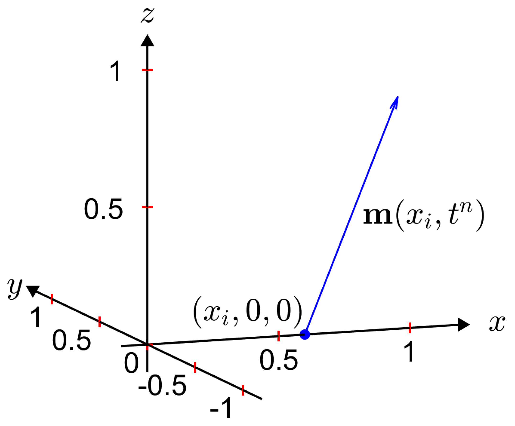
where t n = t n 1 + Δ t n , for  n 1 , Δ t n is the nonuniform time step size, and  t 0 = 0 . The visualization of m i n is shown in Figure 2.
Similarly, f i n = f ( x i , t n ) . The explicit Euler scheme is given as
m i n + 1 m i n Δ t n + 1 = m i n × Δ h m i n + f i n , 1 i N x   and   0 n N t .
where the discrete Laplacian is defined as Δ h m i n = ( m i + 1 n 2 m i n + m i 1 n ) / h 2 , and N t is the number of iterations. The periodic boundary condition ( m 0 n = m N x n and m N x + 1 n = m 1 n ) is applied for n 0 . That is,  
Δ h m 1 n = m 2 n 2 m 1 n + m 0 n h 2 = m 2 n 2 m 1 n + m N x n h 2 , Δ h m N x n = m N x + 1 n 2 m N x n + m N x 1 n h 2 = m 1 n 2 m N x n + m N x 1 n h 2 .
Define the discrete energy function [31] as follows:
E ( m n ) = h i = 1 N x m i n 2 = h i = 1 N x m i + 1 n m i n h 2 = 1 h i = 1 N x ( u i + 1 n u i n ) 2 + ( v i + 1 n v i n ) 2 + ( w i + 1 n w i n ) 2 .
In particular, the energy function is conserved when the forcing term f = 0 [23].

2.2. Adaptive Time-Stepping Algorithm

Now, we present the adaptive time-stepping method. We set a maximum displacement of the numerical solution within a single time step by a tolerance t o l . Multiplying both sides of Equation (16) by Δ t n + 1 , we obtain
m i n + 1 m i n = Δ t n + 1 m i n × Δ h m i n + f i n , 1 i N x .
A maximum norm is defined as follows:
m = max 1 i N x | m i | .
Then, from Equation (3), we require that the following condition be satisfied:
m n + 1 m n = Δ t n + 1 m n × Δ h m n + f n t o l .
In this study, we use the maximum norm instead of the l 2 -norm, which measures the average, because the maximum norm is more effective for assessing the largest individual component in a vector and ensures that no single variable dominates the vector’s magnitude. From Equation (5), we have the constraint of the time step sizes:
Δ t n + 1 t o l m n × Δ h m n + f n .
Then, we use
Δ t n + 1 = min t o l m n × Δ h m n + f n , Δ t max ,
where Δ t max is a given maximum time step size that guarantees stability. From Equation (3), we have the next time solution:
m i n + 1 = m i n + Δ t n + 1 m i n × Δ h m i n + f i n , 1 i N x .
However, generally, | m i n + 1 | 1 for some i. We normalize it as
m i n + 1 = m i n + 1 | m i n + 1 | , 1 i N x .
Repeat this process while t n + Δ t n + 1 T to calculate the numerical approach of m ( x , T ) . When determining adaptive time steps, t n + 1 can exceed the desired final time. In order to avoid such circumstance, if  t n + 1 = t n + Δ t n + 1 > T , then set Δ t n + 1 = T t n .
We present a detailed numerical algorithm for each step of the proposed method in Algorithm 1.
Algorithm 1: Adaptive scheme for the LL equation
INPUT  endpoints L x , R x ; number of grid points N x ; initial condition; final time T; tolerance tol ; maximum time step size Δ t max ; forcing term ( f u , f v , f w ) .
OUTPUT   approximation of m ( x , T ) = ( u ( x , T ) , v ( x , T ) , w ( x , T ) ) .
Step 1 Initialization
        Set h = ( R x L x ) / N x and t = 0
        For i = 1 , , N x do
         x i = L x + ( i 0.5 ) h
         u i 0 = u 0 ( x i ) ,     v i 0 = v 0 ( x i ) ,     w i 0 = w 0 ( x i )
Step 2 While ( t < T ), do Steps 3–7.
   Step 3 For i = 1 , , N x do
          Δ h u i n = ( u i + 1 n 2 u i n + u i 1 n ) / h 2
          Δ h v i n = ( v i + 1 n 2 v i n + v i 1 n ) / h 2
          Δ h w i n = ( w i + 1 n 2 w i n + w i 1 n ) / h 2 .
       Use periodic boundary condition
   Step 4 Set s u , i n = w i n Δ h v i n v i n Δ h w i n + f u , i n
         s v , i n = u i n Δ h w i n w i n Δ h u i n + f v , i n
         s w , i n = v i n Δ h u i n u i n Δ h v i n + f w , i n .
   Step 5 Set d i s = max 1 i N x | ( s u , i n , s v , i n , s w , i n ) | ;
         Δ t = min ( 0.99 t o l / d i s , Δ t max ) .
       If t + Δ t > T , then Δ t = T t .
   Step 6 Set    u i * = u i n + Δ t s u , i n
         v i * = v i n + Δ t s v , i n
         w i * = w i n + Δ t s w , i n .
   Step 7 Set    u i n + 1 = u i * / | ( u i * , v i * , w i * ) |
         v i n + 1 = v i * / | ( u i * , v i * , w i * ) |
         w i n + 1 = w i * / | ( u i * , v i * , w i * ) | .
        t = t + Δ t .
Step 8 OUTPUT u ( x , T ) , v ( x , T ) , w ( x , T )
   STOP.
Remark 1.
We use the maximum norm between m n + 1 and m n for the criterion for selecting an adaptive time step, which ensures that the maximum displacement falls within a predefined tolerance threshold. The rationale for using the maximum norm between m n + 1 and m n is to decrease the time step when the temporal evolution is rapid and to increase it when the evolution is slow.
Remark 2.
The proposed time adaptivity method is different from a well-known method such as the adaptive Runge–Kutta–Fehlberg (RKF) method, which is based on both higher- and lower-order numerical schemes [32]. The adaptive RKF method has been successfully applied for the Allen–Cahn equation [28]. The RKF method is a numerical technique with higher order than our proposed method. If we assume that the numerical solution changes rapidly, the local error generated by the adaptive time-stepping method based on the RKF method will be relatively smaller than that of our proposed method. However, when calculating the time step size adaptively, the adaptive time-stepping method based on the RKF method cannot calculate it at once because it does not know the time step size advance.
Although our proposed time adaptivity method has lower-order than the adaptive time-stepping method based on the RKF method, it is easy and simple to numerically implement, and it has the advantage of being computationally efficient, because it does not require recomputing numerical solutions when the updated solution does not satisfy a certain condition, as is done in [28]. Our proposed updating algorithm is a one-step method. In addition, our proposed method can continuously reduce the time step size as the numerical solution is updated, which is a drawback that can be compensated for by separately considering the conditions for determining the lower bound. In [33], an optimization of explicit Runge–Kutta schemes up to six-order accuracy was presented for ordinary differential equation. The authors proposed a method for selecting optimal free coefficients based on minimizing residual terms and ensuring interpolational properties.

3. Computational Experiments

We shall study the achievement of the proposed adaptive time-stepping method through several computational experiments. We begin with the comparison study between the numerical and analytic solution for the forcing term.

3.1. Without Forcing Term f 0

Now, we perform a convergence test when f 0 on a computational domain Ω = ( 0 , 1 ) and h = 1 / 100 . The analytic solution [4] of the equation can be defined as
u e ( x , t ) = sin ( α ) cos ( k x + t k 2 cos ( α ) ) , v e ( x , t ) = sin ( α ) sin ( k x + t k 2 cos ( α ) ) , w e ( x , t ) = cos ( α ) ,
where α = 0.25 π , k = 2 π . The boundary condition with periodic recurrence is considered as m 0 = m N x and m N x + 1 = m 1 . An initial condition is given as follows:
u ( x , 0 ) , v ( x , 0 ) , w ( x , 0 ) = ( sin ( α ) cos ( k x ) , sin ( α ) sin ( k x ) , cos ( α ) ) .
Then, we can observe that m ( x , t ) = ( u e ( x , t ) , v e ( x , t ) , w e ( x , t ) ) meets Equation (1), the initial condition, and the periodic boundary condition.
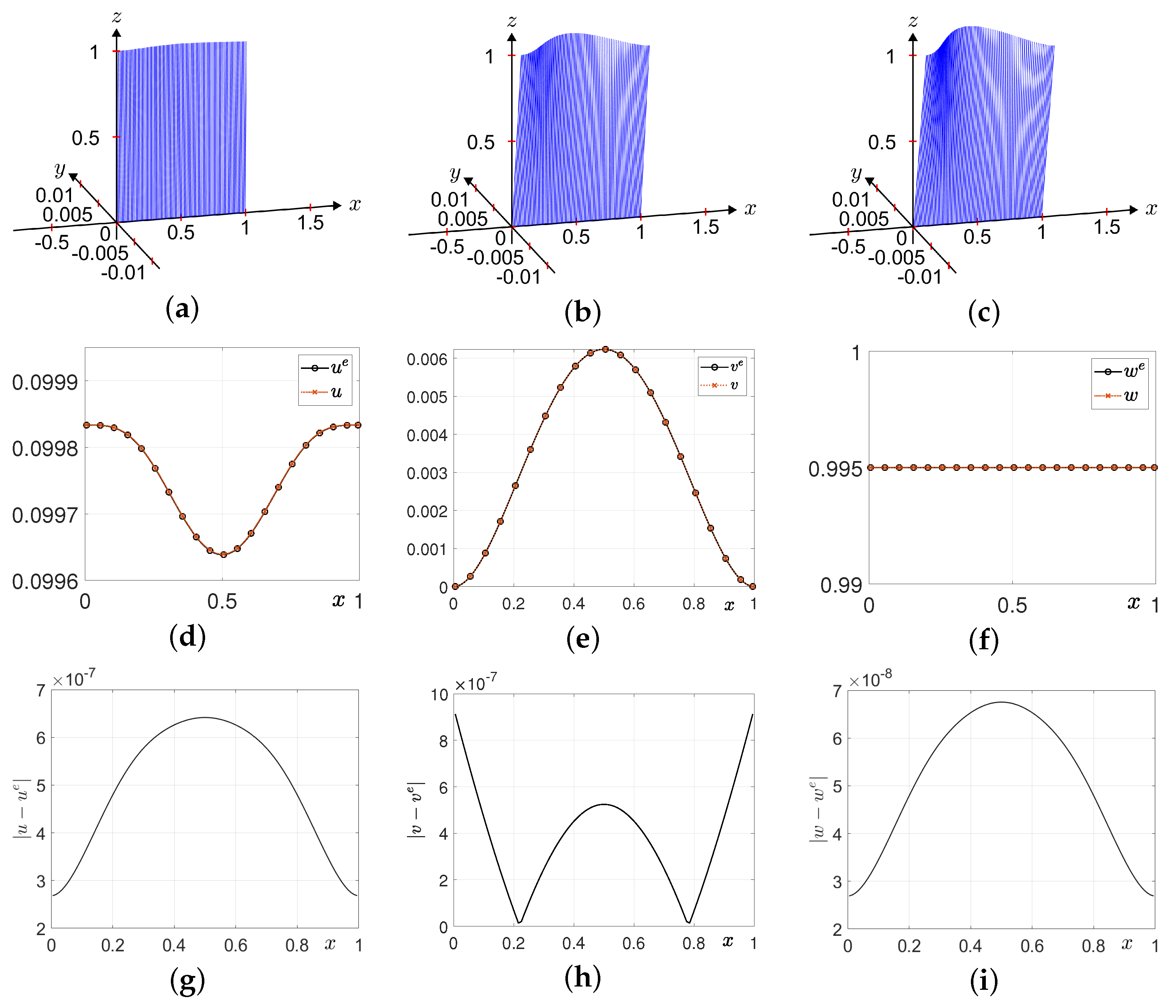
Figure 3a–c display the snapshots of the computational results of m ( x , t ) at t = 0.01 , 0.07 , and  0.1 , respectively. Figure 3d–f display the numerical solutions to u ( x , t ) , v ( x , t ) , and  w ( x , t ) with the matching exact solutions at t = 0.1 , respectively. The differences between the exact solution and the computational solutions u ( x , t ) , v ( x , t ) , and  w ( x , t ) , shown in Figure 3g–i, respectively, are evaluated at t = 0.1 . Here, we use tolerance t o l = 10 6 , α = 0.25 π and maximum time step size Δ t max = 0.5 h 2 . In case f = 0 , we verify that the energy is conserved. Figure 3j shows the discrete energy variation over time.

3.2. Periodic Forcing Term

We consider a one-dimensional LL equation on domain Ω = ( 0 , 1 ) , N x = 100 and h = 1 / 100 with a forcing term
m t = m × m x x + f ,
which has an exact solution [4]
m e ( x , t ) = u e ( x , t ) v e ( x , t ) w e ( x , t ) = cos ( x 2 ( 1 x ) 2 ) sin ( t ) sin ( x 2 ( 1 x ) 2 ) sin ( t ) cos ( t ) .
Therefore, a corresponding forcing term is adopted for the governing LL equation. For brevity, we used X = x 2 ( 1 x ) 2 .  
f = m t + m × m x x = cos ( X ) cos ( t ) + [ ( X ) 2 sin ( X ) X cos ( X ) ] sin ( t ) cos ( t ) sin ( X ) cos ( t ) + [ ( X ) 2 cos ( X ) + X sin ( X ) ] sin ( t ) cos ( t ) sin ( t ) + X sin 2 ( t ) .
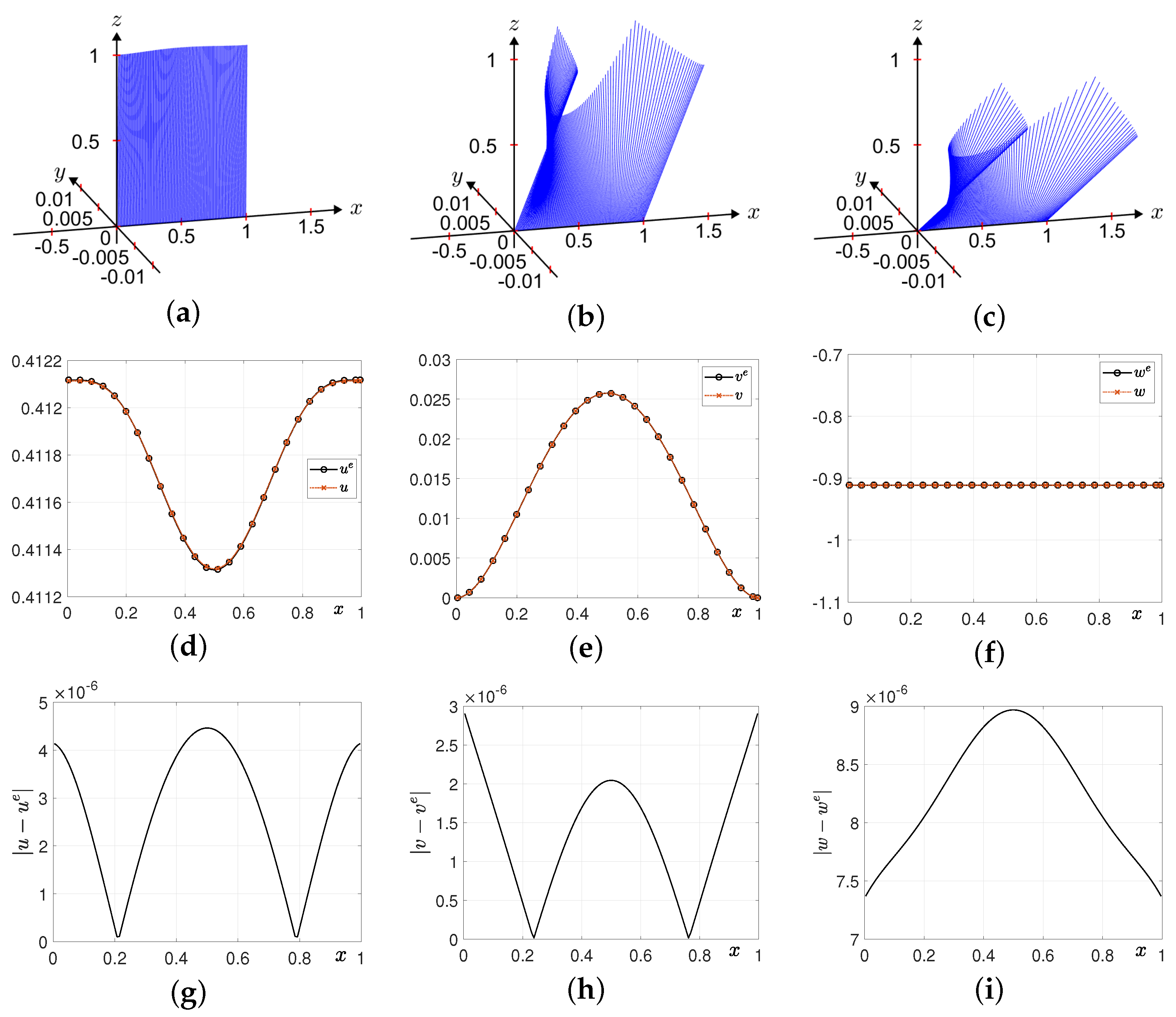
The computational domain is defined as explained in Section 2.1. For final time T = 0.1 , tolerance t o l = 10 7 and maximum time step size Δ t max = 0.5 h 2 are selected as appropriate parameter values. Figure 4a–c show the snapshots of the computational results of m ( x , t ) at t = 0.01 , 0.07 , and  0.1 , respectively. Figure 4d–f and g–i display the numerical solutions and differences of u ( x , t ) , v ( x , t ) , and  w ( x , t ) with the matching exact solutions at t = 0.1 , respectively. Computational results are represented by a circle, and analytic solutions are represented by solid lines. We can see that the results from the proposed method show good agreement with the exact solution. See Appendix A Table A1 for enumerated parameters.

3.3. Non-Periodic Forcing Term

In this section, we present a computational experiment that rapidly changes over time. The proposed time adaptive approach has its strength where the change of the solution is rapid and diverse during the numerical simulation. Therefore, we apply the following exact solution and corresponding forcing term in Equation (10):
m e ( x , t ) = u e ( x , t ) v e ( x , t ) w e ( x , t ) = cos ( x 2 ( 1 x ) 2 ) sin ( 100 t 2 ) sin ( x 2 ( 1 x ) 2 ) sin ( 100 t 2 ) cos ( 100 t 2 ) ,
f = m t + m × m x x
= 200 t cos ( X ) cos ( 100 t 2 ) + [ ( X ) 2 sin ( X ) X cos ( X ) ] sin ( 100 t 2 ) cos ( 100 t 2 ) 200 t sin ( X ) cos ( 100 t 2 ) + [ ( X ) 2 cos ( X ) + X sin ( X ) ] sin ( 100 t 2 ) cos ( 100 t 2 ) 200 t sin ( 100 t 2 ) + X sin 2 ( 100 t 2 ) .
To show the rapid change of the solution over time, Figure 5 illustrates the exact solution w e ( x , t ) = cos ( 100 t 2 ) . The forcing term introduced in this section is no longer periodic. Therefore, we use the homogeneous Neumann boundary condition instead of the periodic boundary condition. Therefore, m 0 = m 1 and m N x + 1 = m N x is applied. On the computational domain ( 0 , 1 ) with h = 1 / 128 , we apply tolerance 5 × 10 7 , maximum time step size Δ t max = 0.005 h 2 and find the numerical solution at final time T = 0.3 . Snapshots of the computational results at t = 0.01 , 0.07 and 0.1 are illustrated in Figure 6a–c, respectively. Figure 6d–i shows the numerical solutions and difference between the numerical solution and exact solution of u, v and w from left to right. For error comparison, we use the discrete maximum error defined as follows:
m m e = max | u u e | + | v v e | + | w w e | .
The execution time is 767.9768 s, and the maximum error is 1.5237 × 10 5 .
Figure 7 illustrates the temporal evolution of the adaptive time step until final time T. The time step decreases as evolution processes, and we can find the major advantage of our proposed model. If a constant time step is applied, the minimum value of Δ t in Figure 7 must be used, which is unnecessary in most of the evolution. For example, before time t = 0.05 , the required time step Δ t is around six times the size of the initial step size. The time step size applied at t = 0.3 is 3.52 × 10 9 , which is approximately 100 times smaller than the initial time step. Assume that a constant time step is applied, which is the minimum step size in Figure 7. Because the adaptive step size decreases exponentially, a smaller time step must be applied for the constant time step method, which will decrease the efficiency of the calculation. Therefore, the proposed adaptive time step not only shows a better performance than the constant time step method but also increases the efficiency as a bigger total time is applied.
Next, we present a comparison between the proposed adaptive time step method and the constant time step methods: the explicit method and the Crank–Nicolson method studied by Jeong and Kim [4]. Jeong and Kim proposed a finite difference method for the LL equation using the Crank–Nicolson method and multigrid method for handling nonlinearities.
Figure 8 shows the numerical results for the explicit method with constant time step Δ t = 1.3737 × 10 8 . Figure 8a–c show the temporal evolution of the numerical solutions at t = 0.01 , t = 0.07 , and  t = 0.1 , respectively. Figure 8d–f show the numerical and analytic solutions of u, v, and w at t = 0.3 . Figure 8g–i show the difference between the numerical and analytic solutions for u, v, and w. The execution time is 901.6647 s, and the maximum error is 1.57 × 10 5 .
Under the equal benchmark problem, we applied constant time step Δ t = 2 × 10 8 . Figure 9 shows numerical results for the Crank–Nicolson method with a constant time step. The first row of Figure 9 shows the temporal evolution of the numerical solutions at t = 0.01 , t = 0.07 , and  t = 0.1 . The second row of Figure 9 shows the numerical and analytic solutions of u, v, and w at t = 0.3 . The last row of Figure 9 shows the difference between the numerical and analytic solutions for u, v, and w. The execution time is 1123.6650 s, and the maximum error is 1.02 × 10 5 .
Through Figure 6, Figure 8 and Figure 9, we compared the results of the explicit adaptive time step method, the constant time step method, and the Crank–Nicolson method for a rapidly changing solution. From these results, the adaptive time step method proved to be better than the constant time step method in terms of both execution time and error. While the first-order adaptive time step method showed slightly larger errors compared to the second-order Crank–Nicolson method, it achieve a similar level of error with significantly less execution time. Furthermore, the proposed adaptive method has the advantage that the trial and error of finding a suitable time step is unnecessary. If a desired tolerance is given, the adaptive time step size is automatically given. However, when applying the Crank–Nicolson method, attempts for finding a suitable time step must be previously performed. Therefore, if we include this procedure in account, the proposed method has a superiority compared to the Crank–Nicolson method.
In concluding this section, we shall provide the maximum error as a function of the tolerance in order to illustrate the behavior of the controller for many levels of accuracy. We used the exact solution and forcing term introduced in this section on the computational domain ( 0 , 1 ) with h = 1 / 128 at final time T = 0.1 . Under maximum step size Δ t max = 0.5 h 2 , maximum errors at tolerance t o l = 10 7 , 1.2 × 10 6 , 2.3 × 10 6 , 2.3 × 10 6 , 3.4 × 10 6 , 4.5 × 10 6 , 5.6 × 10 6 , 6.7 × 10 6 , 7.8 × 10 6 , 8.9 × 10 6 , 10 5 are illustrated in Figure 10. We can see that after the first data, the maximum error linearly grows with the tolerance.

3.4. Damping Forcing Term

Next, we consider a one-dimensional LL equation on domain Ω = ( 0 , 2 π ) with a damping forcing term. The exact solution and corresponding forcing term are given as follows:
m e ( x , t ) = u e ( x , t ) v e ( x , t ) w e ( x , t ) = sec h ( α t ) cos ( x ) sec h ( α t ) sin ( x ) tan h ( α t ) , f ( x , t ) = m t e ( x , t ) + m e ( x , t ) × m x x e ( x , t ) = ( v e ( x , t ) α u e ( x , t ) ) w e ( x , t ) ( u e ( x , t ) α v e ( x , t ) ) w e ( x , t ) α [ 1 ( w e ( x , t ) ) 2 ] .
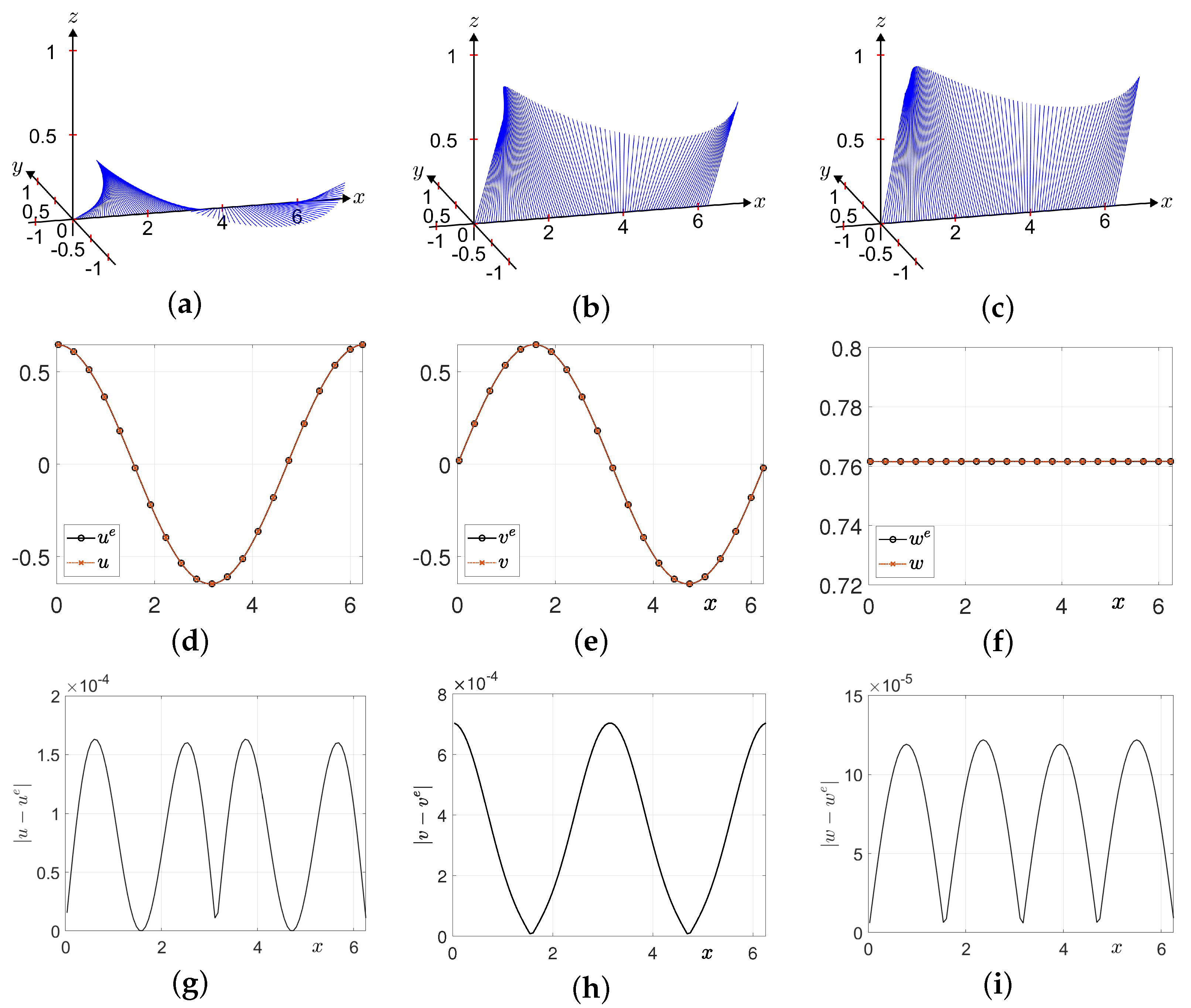
Figure 11a–c show the snapshots of the computational results of m ( x , t ) at t = 0.0001 , 0.0007 , and  0.001 , respectively. Figure 11d–f display the numerical approximations of u ( x , t ) , v ( x , t ) , and  w ( x , t ) with the corresponding exact solutions at t = 0.01 , respectively. Figure 11g–i illustrate the difference of u ( x , t ) , v ( x , t ) , and  w ( x , t ) with the matching exact solutions at t = 0.01 , respectively. Here, we use N x = 100 , h = 2 π / N x , α = 1000 , t o l = 10 5 , and  Δ t max = 0.5 h 2 .
Lastly, we simulate the case where the forcing term is constant, f = ( 0 , 0 , 1 ) T with the same computational domain as the last numerical simulation. Tolerance 10 7 is applied. The constant forcing term represents the constant one directional external magnetic field that is applied to the dynamics of magnetization. The initial condition is given as m ( x , 0 ) = ( cos ( x ) / 2 , sin ( x ) / 2 , 1 / 2 ) T . Figure 12a–c show the snapshots of the computational results of m ( x , t ) at t = 0.001 , 0.007 , and  0.01 , respectively. Figure 12d–f display the numerical approximations of u ( x , t ) , v ( x , t ) , and  w ( x , t ) with the corresponding exact solutions at t = 0.01 , respectively. We can see the numerical results are stable and therefore capable of simulating this application.

4. Conclusions

The article introduced a new adaptive time-stepping FDM for solving the LL equation, which is crucial for investigating magnetic materials and processes. The method strategically selects time steps to keep displacement within a tolerance and allows larger steps near equilibrium states for faster computations. Benchmark tests demonstrated the algorithm’s efficiency and accuracy and showed its potential for advancing magnetic phenomena analysis. We expect that the proposed time-stepping adaptive method can be applied to various equations which can be numerically approximated. Reaction–diffusion equations such as the Allen–Cahn equation can make good use of the proposed method because the displacement of the numerical solution is determined by the time step size. Furthermore, the evolution of the numerical solution varies during the numerical simulation, which indicates that the adaptive time step can be an efficient solution.
In this paper, we considered a one-dimensional LL equation. Extending the proposed method to multi-dimensional problems presents challenges for explicit methods in terms of stability, which is a limitation of this study. Oscillations have already been reported in one-dimensional problems. We expect that adopting an implicit method combined with the adaptive time-stepping method could provide a solution for the multi-dimensional LL problem. In future work, we will present an efficient adaptive time-stepping method for the LL Equation (1) in two- and three-dimensional spaces. As a preliminary model, we consider the two-dimensional case as follows. In two-dimensional space, Equation (1) on Ω = ( L x , R x ) × ( L y , R y ) is defined as
m ( x , y , t ) t = m ( x , y , t ) × Δ m ( x , y , t ) + f ( x , y , t ) , ( x , y ) Ω , 0 < t T .
Let N x and N y be positive integers. The discrete computational domain is defined as Ω h = { ( x i = L x + ( i 0.5 ) h , y j = L y + ( j 0.5 ) h ) | i = 1 , 2 , , N x , j = 1 , 2 , , N y } , where the spatial step size h = ( R x L x ) / N x = ( R y L y ) / N y . We discretize Equation (15) as
m i j n + 1 m i j n Δ t n + 1 = m i j n × m i + 1 , j n + m i 1 , j n + m i , j + 1 n + m i , j 1 n 4 m i j n h 2 + f i j n .
We consider the case without the forcing term, where f 0 . An exact solution of Equation (15) is given by [4]
u e ( x , y , t ) = sin π 24 cos 2 π ( x + y ) + 8 π t cos π 24 , v e ( x , y , t ) = sin π 24 sin 2 π ( x + y ) + 8 π t cos π 24 , w e ( x , y , t ) = cos π 24 .
The initial condition on the Ω = ( 0 , 1 ) × ( 0 , 1 ) is given by
u ( x , y , 0 ) , v ( x , y , 0 ) , w ( x , y , 0 ) = sin π 24 cos ( 2 π ( x + y ) ) , sin π 24 sin ( 2 π ( x + y ) ) , cos π 24 .
We used the parameters N x = N y = 32 , t o l = 10 6 , Δ t m a x = 0.2 h 2 , and the final time T = 0.1 . For visualization of the numerical solution at time t = 0.1 , we used the scaled numerical solution 0.25 m i j for i = 1 , 3 , 5 , , 31 , j = 1 , 3 , 5 , , 31 . Figure 13 shows the scaled numerical solutions at t = 0 and t = 0.1 using the adaptive time-stepping method.
Future work will focus on extending the proposed adaptive method to another class of partial differential equations with a similar structure, particularly those involving fast and slow evolutions such as the Allen–Cahn equation [34], the Black–Scholes equation [35], and the Susceptible–Infected–Recovered (SIR) epidemic model [36].

Author Contributions

Conceptualization, J.K. and H.K.; methodology, J.K., H.K. and S.K. (Soobin Kwak); software, H.K., S.K. (Soobin Kwak), M.M., S.K. (Seungyoon Kang) and S.H.; validation, M.M., S.K. (Soobin Kwak) and S.H.; formal analysis, H.K. and J.K.; investigation, S.K. (Seungyoon Kang) and M.M.; resources, S.K. (Seungyoon Kang) and S.H.; data curation, S.K. (Seungyoon Kang) and S.H.; writing—original draft, H.K., S.K. (Soobin Kwak), M.M., S.K. (Seungyoon Kang), S.H. and J.K.; writing—review and editing, H.K., S.K. (Soobin Kwak), S.H., S.K. (Seungyoon Kang) and J.K.; visualization, S.K. (Soobin Kwak) and S.H.; supervision, H.K. and J.K.; project administration, J.K.; funding acquisition, H.K. and J.K. All authors have read and agreed to the published version of the manuscript.

Funding

The first author (Hyundong Kim) was supported by the Basic Science Research Program through the National Research Foundation of Korea (NRF) funded by the Ministry of Education (2021R1A6A1A03044326). The corresponding author (J.S. Kim) received support from the Brain Korea 21 (BK 21) FOUR program funded by the Ministry of Education.

Data Availability Statement

The raw data supporting the conclusions of this article will be made available by the authors on request.

Acknowledgments

The authors thank the reviewers for their constructive and helpful comments on the revision of this article.

Conflicts of Interest

The authors declare no conflicts of interest.

Appendix A

The following MATLAB code produces the results shown in Figure 3, and the parameters are enumerated in Table A1. The code can also be downloaded from https://mathematicians.korea.ac.kr/cfdkim/open-source-codes/ (accessed on 23 December 2024). Compared to other programs in the market, MATLAB is highly beneficial in a way that it serves as a unified platform that can provide powerful numerical computation through coding and a comprehensive set of tools for data visualization. Because both functionalities are available, the user can interactively check and modify variables in the workspace and memory and visualize it instantaneously. Moreover, MATLAB boasts an extensive functionality through extensional toolboxes and built-in functions that can boost the work speed of the user.
In this paper, the LL equation in a small scale is simulated through MATLAB. We expect that the proposed method can be expanded to larger-scale problems that handle practical engineering applications with the help of additional computational methods such as parallel computing.
Table A1. Parameters used for the 1D LL equation.
ParametersDescription
Nxnumber of grid points on the x-axis
Lxminimum value on the x-axis
Rxmaximum value on the x-axis
hspace step size
Tfinal time
maxdtmaximum time step size
toltolerance
clear;
Nx=100; Lx=0; Rx=1; h=(Rx-Lx)/Nx; x=linspace(Lx+0.5*h,Rx-0.5*h,Nx);
XX=(x.^2).*((1-x).^2); dXX=2*x-6*x.^2+4*x.^3; ddXX=2-12*x+12*x.^2;
ue=@(t) sin(t).*cos(XX);
ve=@(t) sin(t).*sin(XX);
we=@(t) cos(t).*ones(1,Nx);
T=1.e-1; maxdt=0.5*h^2; t=0; u=ue(0); v=ve(0); w=we(0); tol=1.e-7;
while t<T
  Lapu(1)=(u(2)-2*u(1)+u(Nx))/h^2;
  Lapv(1)=(v(2)-2*v(1)+v(Nx))/h^2;
  Lapw(1)=(w(2)-2*w(1)+w(Nx))/h^2;
  for  i=2:Nx-1
    Lapu(i)=(u(i+1)-2*u(i)+u(i-1))/h^2;
    Lapv(i)=(v(i+1)-2*v(i)+v(i-1))/h^2;
    Lapw(i)=(w(i+1)-2*w(i)+w(i-1))/h^2;
  end
  Lapu(Nx)=(u(1)-2*u(Nx)+u(Nx-1))/h^2;
  Lapv(Nx)=(v(1)-2*v(Nx)+v(Nx-1))/h^2;
  Lapw(Nx)=(w(1)-2*w(Nx)+w(Nx-1))/h^2;
  fu=cos(XX).*cos(t)+(dXX.^2.*sin(XX)-ddXX.*cos(XX))*sin(t)*cos(t);
  fv=sin(XX).*cos(t)-(dXX.^2.*cos(XX)+ddXX.*sin(XX))*sin(t)*cos(t);
  fw=-sin(t)+ddXX*sin(t).^2;
  su=v.*Lapw-w.*Lapv-fu;
  sv=w.*Lapu-u.*Lapw-fv;
  sw=u.*Lapv-v.*Lapu-fw;
  en=max(sqrt(su.^2+sv.^2+sw.^2));
  dt=0.99*tol/en; dt=min(dt,maxdt);
  if (t+dt>T)
    dt=T-t;
  end
  t=t+dt;
  nu=u-dt*su; nv=v-dt*sv; nw=w-dt*sw;
  u=nu; v=nv; w=nw;
  A=[u’ v’ w’];
  for i=1:Nx
    B(i)=norm(A(i,:));
  end
  u=u./B; v=v./B; w=w./B;
end
        

References

  1. Landau, L.; Lifshitz, E. On the theory of the dispersion of magnetic permeability in ferromagnetic bodies. Phys. Z. Sowjetunion 1935, 8, 101–114. [Google Scholar]
  2. Bertotti, G.; Mayergoyz, I.D.; Serpico, C. Analytical solutions of Landau–Lifshitz equation for precessional dynamics. Physica B 2004, 343, 325–330. [Google Scholar] [CrossRef]
  3. García-Ñustes, M.A.; Humire, F.R.; Leon, A.O. Self-organization in the one-dimensional Landau–Lifshitz–Gilbert–Slonczewski equation with non-uniform anisotropy fields. Commun. Nonlinear Sci. Numer. Simul. 2021, 96, 105674. [Google Scholar] [CrossRef]
  4. Jeong, D.; Kim, J. A Crank–Nicolson scheme for the Landau–Lifshitz equation without damping. J. Comput. Appl. Math. 2010, 234, 613–623. [Google Scholar] [CrossRef]
  5. Jeong, D.; Kim, J. An accurate and robust numerical method for micromagnetics simulations. Curr. Appl. Phys. 2014, 14, 476–483. [Google Scholar] [CrossRef]
  6. Sharma, H.; Borggaard, J.; Patil, M.; Woolsey, C. Performance assessment of energy-preserving, adaptive time-step variational integrators. Commun. Nonlinear Sci. Numer. Simul. 2022, 114, 106646. [Google Scholar] [CrossRef]
  7. Moumni, M.; Tilioua, M. A finite-difference scheme for a model of magnetization dynamics with inertial effects. J. Eng. Math. 2016, 100, 95–106. [Google Scholar] [CrossRef]
  8. Li, P.; Xie, C.; Du, R.; Chen, J.; Wang, X.P. Two improved Gauss-Seidel projection methods for Landau–Lifshitz–Gilbert equation. J. Comput. Phys. 2020, 401, 109046. [Google Scholar] [CrossRef]
  9. Jannelli, A. Adaptive numerical solutions of time-fractional advection–diffusion–reaction equations. Commun. Nonlinear Sci. Numer. Simul. 2022, 105, 106073. [Google Scholar] [CrossRef]
  10. Wang, X.P.; García-Cervera, C.J.; Weinan, E. A Gauss–Seidel projection method for micromagnetics simulations. J. Comput. Phys. 2001, 171, 357–372. [Google Scholar] [CrossRef]
  11. Dörfler, M. Quilted Gabor frames—A new concept for adaptive time-frequency representation. Adv. Appl. Math. 2011, 47, 668–687. [Google Scholar] [CrossRef]
  12. Alouges, F. A new finite element scheme for Landau–Lifshitz equations. Discrete Contin. Dyn. Syst. Ser. S 2008, 1, 187–196. [Google Scholar]
  13. Alouges, F.; Jaisson, P. Convergence of a finite element discretization for the Landau–Lifshitz equations in micromagnetism. Math. Models Methods Appl. Sci. 2006, 16, 299–316. [Google Scholar] [CrossRef]
  14. Mohammed, M.; Mouhcine, T. A finite element approximation of a current-induced magnetization dynamics model. J. Math. Model. 2022, 10, 53–69. [Google Scholar]
  15. Moumni, M.; Douiri, S.M.; Kim, J.S. Fourier-spectral method for the Landau–Lifshitz–Gilbert equation in micromagnetism. Results Appl. Math. 2023, 19, 100380. [Google Scholar] [CrossRef]
  16. Weinan, E.; Wang, X.P. Numerical methods for the Landau–Lifshitz equation. SIAM J. Numer. Anal. 2001, 39, 1647–1665. [Google Scholar]
  17. Yang, W.; Wang, D.; Yang, L. A stable numerical method for space fractional Landau–Lifshitz equations. Appl. Math. Lett. 2016, 61, 149–155. [Google Scholar] [CrossRef]
  18. Cimrák, I. A survey on the numerics and computations for the Landau–Lifshitz equation of micromagnetism. Arch. Comput. Methods Eng. 2007, 15, 1–37. [Google Scholar] [CrossRef]
  19. Bastos, J.P.A.; Sadowski, N. Magnetic Materials and 3D Finite Element Modeling; CRC Press: Boca Raton, FL, USA, 2017. [Google Scholar]
  20. Cai, Y.; Chen, J.; Wang, C.; Xie, C. Error analysis of a linear numerical scheme for the Landau–Lifshitz equation with large damping parameters. Math. Methods Appl. Sci. 2023, 46, 18952–18974. [Google Scholar] [CrossRef]
  21. Chen, J.; Wang, C.; Xie, C. Convergence analysis of a second-order semi-implicit projection method for Landa–Lifshitz equation. Appl. Numer. Math. 2021, 168, 55–74. [Google Scholar] [CrossRef]
  22. Yang, Y.B.; Jiang, Y.L. Unconditional optimal error estimates of linearized second-order BDF Galerkin FEMs for the Landau–Lifshitz equation. Appl. Numer. Math. 2021, 159, 21–45. [Google Scholar] [CrossRef]
  23. Fuwa, A.; Ishiwata, T.; Tsutsumi, M. Finite difference scheme for the Landau–Lifshitz equation. Jpn. J. Ind. Appl. Math. 2012, 29, 83–110. [Google Scholar] [CrossRef]
  24. Magaletti, F.; Gallo, M.; Perez, S.P.; Carrillo, J.A.; Kalliadasis, S. A positivity-preserving scheme for fluctuating hydrodynamics. J. Comput. Phys. 2022, 463, 111248. [Google Scholar] [CrossRef]
  25. Daribayev, B.; Mukhanbet, A.; Azatbekuly, N.; Imankulov, T. A quantum approach for exploring the numerical results of the heat equation. Algorithms 2024, 17, 327. [Google Scholar] [CrossRef]
  26. Krivovichev, G.V. Stability optimization of explicit Runge–Kutta methods with higher-order derivatives. Algorithms 2024, 17, 535. [Google Scholar] [CrossRef]
  27. Christou, M.A.; Papanicolaou, N.C.; Sophocleous, C. An efficient and highly accurate spectral method for modeling the propagation of solitary magnetic spin waves in thin films. Comput. Appl. Math. 2020, 39, 205. [Google Scholar] [CrossRef]
  28. Lee, C.; Park, J.; Kwak, S.; Kim, S.; Choi, Y.; Ham, S.; Kim, J. An adaptive time-stepping algorithm for the Allen–Cahn equation. J. Funct. Spaces 2022, 2022, 2731593. [Google Scholar] [CrossRef]
  29. Cheng, Q.; Shen, J. Length preserving numerical schemes for Landau–Lifshitz equation based on Lagrange multiplier approaches. SIAM J. Sci. Comput. 2023, 45, A530–A553. [Google Scholar] [CrossRef]
  30. He, J.; Yang, L.; Zhan, J. Temporal High-Order Accurate Numerical Scheme for the Landau–Lifshitz–Gilbert Equation. Mathematics 2024, 12, 1179. [Google Scholar] [CrossRef]
  31. De Laire, A. Recent results for the Landau–Lifshitz equation. SeMA J. 2022, 79, 253–295. [Google Scholar] [CrossRef]
  32. Atkinson, K.; Han, W.; Stewart, D.E. Numerical Solution of Ordinary Differential Equations, 2nd ed.; John Wiley & Sons: Hoboken, NJ, USA, 2009. [Google Scholar]
  33. Alshina, E.A.; Zaks, E.M.; Kalitkin, N.N. Optimal first-to sixth-order accurate Runge-Kutta schemes. Comput. Math. Math. Phys. 2008, 48, 395–405. [Google Scholar] [CrossRef]
  34. Ham, S.; Kim, J. Stability analysis for a maximum principle preserving explicit scheme of the Allen–Cahn equation. Math. Comput. Simul. 2023, 207, 453–465. [Google Scholar] [CrossRef]
  35. Lee, C.; Kwak, S.; Hwang, Y.; Kim, J. Accurate and efficient finite difference method for the Black–Scholes model with no far-field boundary conditions. Comput. Econ. 2023, 61, 1207–1224. [Google Scholar] [CrossRef]
  36. Dieguez, G.; Batistela, C.; Piqueira, J.R.C. Controlling COVID-19 spreading: A three-level algorithm. Mathematics 2023, 11, 3766. [Google Scholar] [CrossRef]
Figure 1. Cell centered computational domain grid.
Algorithms 18 00001 g001
Figure 2. Schematic illustration of m ( x i , t n ) .
Algorithms 18 00001 g002
Figure 3. Numerical solutions at (a) t = 0.01 , (b) t = 0.07 , and (c) t = 0.1 . Numerical and analytic solutions of (d) u ( x , t ) , (e) v ( x , t ) , and (f) w ( x , t ) at t = 0.1 . The differences between the exact solution and the computational solutions (g) u ( x , t ) , (h) v ( x , t ) , and (i) w ( x , t ) at t = 0.1 . (j) The time evolution of discrete energy.
Algorithms 18 00001 g003
Figure 4. Numerical solution at (a) t = 0.01 , (b) t = 0.07 , and (c) t = 0.1 . Numerical and analytic solutions of (d) u, (e) v, and (f) w at t = 0.1 . The differences between the exact solution and the numerical solutions (g) u, (h) v, and (i) w at t = 0.1 .
Algorithms 18 00001 g004
Figure 5. Exact solution w e ( x , t ) = cos ( 100 t 2 ) in Equation (13).
Algorithms 18 00001 g005
Figure 6. Numerical solutions for the proposed adaptive method at (a) t = 0.01 , (b) t = 0.07 , and (c) t = 0.1 . Numerical and analytic solutions of (d) u, (e) v, and (f) w at t = 0.3 . The differences between the exact solution and the numerical solutions (g) u, (h) v, and (i) w at t = 0.3 .
Algorithms 18 00001 g006
Figure 7. Desired adaptive time step Δ t for each time. Adaptive time steps enhance the efficiency of the method.
Algorithms 18 00001 g007
Figure 8. Numerical solutions for the explicit method with constant time step Δ t = 1.3737 × 10 8 at (a) t = 0.01 , (b) t = 0.07 , and (c) t = 0.1 . Numerical and analytic solutions of (d) u, (e) v, and (f) w at t = 0.3 . The differences between the exact solution and the numerical solutions (g) u, (h) v, and (i) w at t = 0.3 .
Algorithms 18 00001 g008
Figure 9. Numerical solutions for the Crank–Nicolson method with constant time step Δ t = 2 × 10 8 at (a) t = 0.01 , (b) t = 0.07 , and (c) t = 0.1 . Numerical and analytic solutions of (d) u, (e) v, and (f) w at t = 0.3 . The differences between the exact solution and the numerical solutions (g) u, (h) v, and (i) w at t = 0.3 .
Algorithms 18 00001 g009
Figure 10. Maximum errors as a function of the tolerance. Tolerance values range from 10 7 to 10 5 .
Algorithms 18 00001 g010
Figure 11. Simulation of damping forcing term. Numerical solution at (a) t = 0.0001 , (b) t = 0.0007 , and (c) t = 0.001 . Numerical and analytic solutions of (d) u, (e) v, and (f) w at t = 0.001 . The differences between the exact solution and the numerical solutions (g) u, (h) v, and (i) w at t = 0.001 .
Algorithms 18 00001 g011
Figure 12. Simulation of constant forcing term. Numerical solution at (a) t = 0.001 , (b) t = 0.007 , and (c) t = 0.01 . Numerical solutions of (d) u, (e) v, and (f) w at t = 0.01 .
Algorithms 18 00001 g012
Figure 13. Numerical solution at (a) t = 0 and (b) t = 0.1 using the adaptive time-stepping method.
Algorithms 18 00001 g013
Disclaimer/Publisher’s Note: The statements, opinions and data contained in all publications are solely those of the individual author(s) and contributor(s) and not of MDPI and/or the editor(s). MDPI and/or the editor(s) disclaim responsibility for any injury to people or property resulting from any ideas, methods, instructions or products referred to in the content.