Abstract
An important element of modern telecommunications is wireless radio networks, which enable mobile subscribers to access wireless networks. The cell area is divided into independent sectors served by directional antennas. As the number of mobile network subscribers served by a single base station increases, the problem of interference related to the operation of the radio link increases. To minimize the disadvantages of omnidirectional antennas, base stations use antennas with directional radiation characteristics. This solution allows you to optimize the operating conditions of the mobile network in terms of reducing the impact of interference, better managing the frequency spectrum and improving the energy efficiency of the system. The work presents an adaptive antenna algorithm used in mobile telephony. The principle of operation of adaptive systems, the properties of their elements and the configurations in which they are used in practice are described. On this basis, an algorithm for controlling the radiation characteristics of adaptive antennas is presented. The control is carried out using a microprocessor system. The simulation model is described. An algorithm was developed based on the Mathcad mathematical program, and the simulation results of this algorithm, i.e., changes in radiation characteristics as a result of changing the mobile position of subscribers, were presented in the form of selected radiation characteristics charts.
1. Introduction
An important element of modern telecommunications are wireless radio networks, which enable mobile subscribers to access the fixed telecommunications network and other wireless networks.
As the number of mobile subscribers served by a single base station increases, the problem of interference related to the operation of the radio link increases. The use of base station antennas with an omnidirectional radiation pattern is not advisable, both from compatibility and energy points of view. When transmitting an antenna with this shape of radiation pattern, an omnidirectional electromagnetic field is generated, which—with the exception of the direction to selected mobile subscribers—is a disturbing field for other stations. At the same time, increasing the number of subscribers does not allow for increasing the frequency spacing of neighboring base stations due to the limited range of the frequency band allocated to a given operator.
In order to minimize the above disadvantages of omnidirectional antennas, antennas with variable directional radiation patterns, adaptive antennas, were used in base stations [1]. These antennas allow their radiation characteristics to be controlled in such a way as to provide mobile subscribers in a given sector with a connection with specified quality parameters, while limiting interference with other base stations.
This solution allows you to optimize the operating conditions of the mobile network in terms of reducing the impact of interference, the better management of the frequency spectrum and improving the energy efficiency of the system.
An adaptive antenna is an antenna that controls its characteristics by controlling the power supply while the antenna is operating [2]. Adaptive antennas are typically constructed from arrays of antennas, with continuous aperture antennas being less common because the characteristics of the antenna array are easily controlled by adjusting the amplitude and phase of the signal from each element before the signals are summed.
Adaptive antennas are useful in radar technology and communication systems where the fight against jamming and interference is an important issue [3]. These antennas change their characteristics automatically in response to the signal environment. This process occurs in such a way as to optimize the signal-to-noise and interference ratio at the output of the array. This makes them particularly useful in protecting radar and communication systems from interference when the direction of the interference is not known in advance. In communication systems, they are also useful in situations where the angle of arrival of the useful signal is not known. Adaptive antennas can work with any shapes of array elements, polarizations, and arrangement of elements. This property is a great advantage when the antenna system must be designed to operate on irregularly shaped surfaces, such as aircraft.
The first news about adaptive antennas appeared around 1950. In 1956, Altman and Sichak proposed the use of a phase-coupled loop to combine signals from different receiving antennas in a collecting system. These arrays were extensively and intensively researched and developed in the 1960s. As a result of research into the problem of eliminating interference, steering antenna beams and tracking moving radio stations, the first solution for adaptive interference elimination began to be developed, dating back to the late 1950s. This concept consisted of zeroing the antenna’s radiation pattern for the directions of space where interference was detected (null steering). The first published results of this research appeared in Applebaum’s work in 1976.
2. Adaptive Antennas in Radio Communications
Mobile radiocommunication is a dynamically developing field of radio communications. Its main task is to ensure communication between mobile subscribers and enable access to the fixed telecommunications network. The area covered by the wireless network is divided into appropriately small sub-areas called cells, within which mobile subscribers move. Each cell is equipped with a base station responsible for collecting and updating user data and intermediating the user’s connection with a selected subscriber of the same network, another network, or a fixed-line network [4]. Dividing the area into cells allows you to reduce the power of transmitters and allows for multiple use of the same frequency range.
The following assumptions apply to the radiocommunication system–mobile telephony, in which the analyzed adaptive antenna control algorithm can be implemented:
- The system works on two frequency ranges [5,6];
- Upstream channels (from mobile station to base station);
- Down channels (from base station to mobile station).
This is a two-way transmission carried out in the frequency domain; depending on the operating frequency, a different bandwidth is used. With the development of mobile radio communication systems and the increasing density of users of these systems, the issue of radio interference generated by base stations and mobile stations becomes more important [7,8]. In the antenna aspect, this refers to the shape of the radiation pattern of the base station antenna. When considering base stations with classic antennas with omnidirectional radiation characteristics or sector characteristics, the harmful impact of co-channel and adjacent-channel interference generated by the assumed evenly distributed electromagnetic field from the base station antennas and the fields generated by mobile stations should be taken into account (Figure 1).
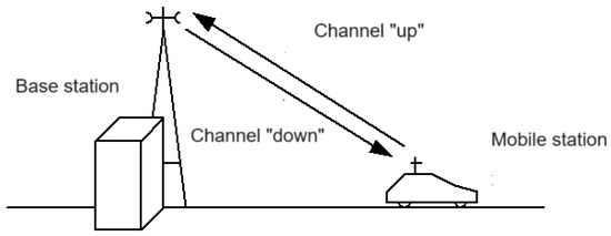
Figure 1.
Communication diagram between the base station and the mobile station.
One of the effective ways to reduce the level of the interference field is to use antennas with directional radiation characteristics in base stations, in particular adaptive antennas with a moving main beam that follows the mobile station in real time. In a similar period, work was carried out independently by Widrow, which was based on the use of the Least Mean Square Algorithm (LMS) to eliminate strong radio interference generated by sources located in close proximity to the received useful stations [9]. The original concept of controlling the zeroing band of the receiving antenna was replaced by a solution of forming a multi-beam radiation pattern of the base station antenna, in which each of the created characteristic lobes is responsible for maintaining communication and tracking a selected mobile station or group of mobile stations (Figure 2) (beam forming) [10,11].
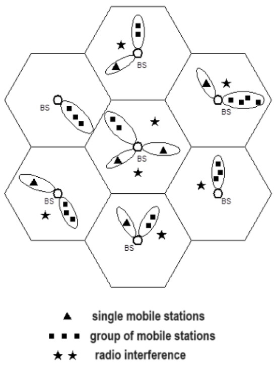
Figure 2.
Land mobile radiocommunication network using base stations with adaptive antennas.
Currently, and in the future, a more effective solution is to combine the method of zeroing the antenna pattern, which eliminates interference, with the simultaneous use of the same antenna as a system with multi-beam radiation characteristics.
Mobile stations located in the area served by a given sector antenna are assigned to a given antenna. This takes place when the area covered by one sector antenna is transferred to another sector. In the new sector, the mobile station receives an identifier that determines its location in the mobile network [12]. When a mobile station requests service, it sends a service request signal on a specific, fixed frequency. The base station checks whether it has free resources to service this mobile station. If so, it allocates a time slot called a physical channel on the appropriate frequency.
A similar situation occurs when the base station receives a request from the exchange to establish a connection to the mobile station. From now on, the mobile station will be operated by an algorithm controlling the radiation pattern of the sector antenna. If there are no resources to service a connection, the connection is lost or there is a wait for the connection to become available, depending on the method used to handle such connection requests.
When the mobile station ends the connection, the physical channel (time slot) it occupies is released and the slot is excluded from the adaptation process [13]. The algorithm for handling calls and ending calls is shown in Figure 3.
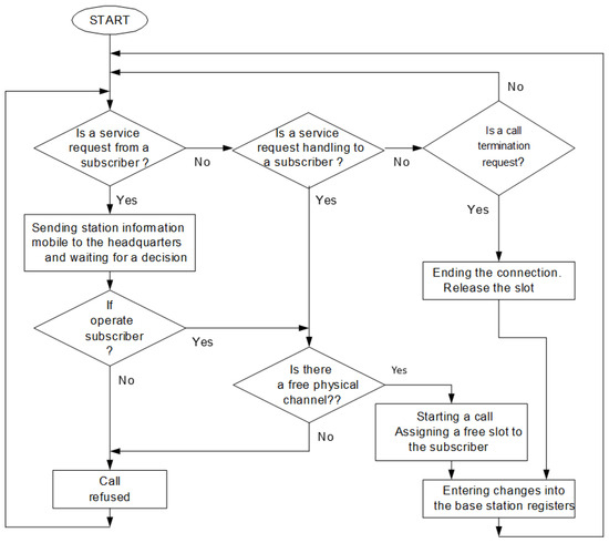
Figure 3.
Algorithm for handling calls and disconnections.
The adaptive algorithm presented [14] in this work is based on the assumption that in subsequent time slots, the adaptive processor determines the parameters of the signal received by the antenna in a given time slot from a given mobile station and modifies the shape of the radiation characteristics of the adaptive array in such a way to adapt this characteristic to the new situation [15]. This is because while the base station serves other subscribers, the mobile station in question may change its position or the power radiated from the transmitter, or an additional signal may occur that will disturb the emission of the mobile station in question or the sector antenna. The power radiated towards the mobile station is also adjusted so that it ensures correct transmission in the radio link, but at the same time introduces the least possible interference to other base stations.
We see that the radiation pattern of the sector antenna changes dynamically in relation to the observed changes in the surroundings of a given base station.
The radiation characteristics of the adaptive antenna are the result of determining optimal characteristics for each mobile station separately. Its form is the sum of the component characteristics for mobile stations. In this way, a radiation pattern is formed that takes into account the location of all currently supported mobile stations as well as the directions of interference that affect the adaptive antenna. Minimizing the radiation characteristics in the direction of the interference source allows the use of lower radiation powers to and from the mobile station while maintaining the assumed connection quality (the ratio of the power of the useful signal to the power of the interfering signals). This introduces less interference to other base and mobile stations and reduces the power of interfering signals and noise occurring in the direction of the operated mobile station.
Data transmission between the mobile station and the base station in a given i-th slot and simultaneously from the base station to the mobile station in the slot (i + 3) is carried out in parallel with the process of the adaptation of the radiation pattern by separate sets of the radio receiver and signal processor.
Although adaptive antenna systems use antennas of various types and configurations, they can be classified into three basic classes:
- Phase patterns;
- Multibeam antennas;
- And their combination.
Each configuration has several ports in which xn signals appear in response to signals from sources located in the antenna illumination field [16]. Therefore, the main problem in implementing the adaptation process is in determining the directions of arrival of signals [17].
A universal way to estimate the signal arrival angle is to use the covariance matrix. The problem comes down to estimating the angle of incidence of signals coming from the directions Θ1, Θ2…Θk based on the received signals x1, x2 xm (Figure 4).
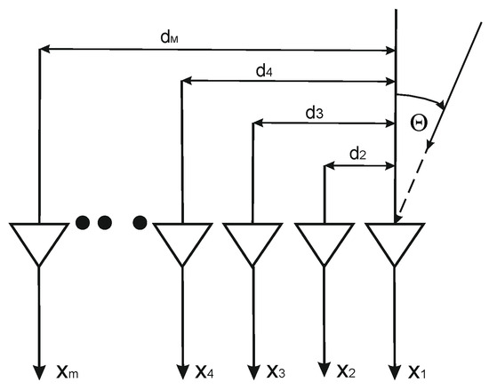
Figure 4.
The m-element antenna array.
The directivity characteristic of a given system can be written as [18]:
where:
—radiation characteristics of a single element of the antenna array (we assume that these elements have the same characteristics);
—complex weight of the adaptive system;
Ax—signal amplitude;
k—propagation vector;
d—distance between array elements;
—phase shift between array elements.
Several useful signals may fall on the antenna system from different directions θ1, …, θK and interfering signals from the directions φ1, …, φL. The signal received by each element will be the sum of all signals, both desired and interfering, reaching the antenna array and thermal noise.
Using the calculated covariance matrix sn, weights are determined for each port of the antenna array. These weights represent a vector of the form [19]:
In general, these are complex quantities, and they affect both the change in the amplitude and phase of each element of the antenna array.
3. Adaptive Algorithm
The adaptive antenna system is based on controlling the radiation characteristics of individual active elements so that the value of the characteristic of the entire antenna is at maximum in the direction of arrival of the useful signal, while in the directions of arrival of interfering signals, the value of the radiation pattern is minimal (theoretically it should be zero, but this is unattainable in practice); however, the nomenclature uses the term zero characteristic in the direction of interference. To achieve this, there are the so-called algorithms for controlling the characteristics of the adaptive array. Most control algorithm solutions can be grouped into four categories (Figure 5).
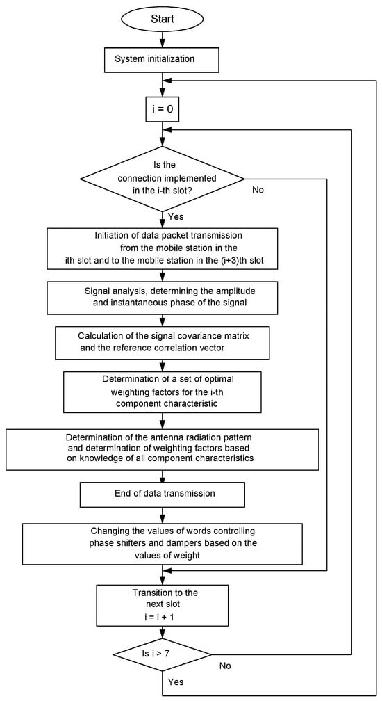
Figure 5.
Adaptive algorithm for the radiation pattern of a sector antenna.
The first one requires a receiver on each of the active elements of the array. In this approach, a correlation matrix of signals received on individual active elements is formed to obtain optimal weights that ensure the maximum useful signal to interference and noise ratio (SINR). There are many solutions of this type, but they all rely on knowing the signals received on individual elements. Using such a number of receivers is expensive and requires constant calibration [20,21].
The second category is a system that relies on knowing the source of the disturbance and on the characteristics of the attenuators and phase shifters being precisely predictable. Having this information, the system mathematically calculates the weights to create a zero characteristic in the direction of the disturbance. However, this method is impractical because the source of the interference is usually unknown.
The third category involves randomly determining possible settings for the weights of array elements. This approach is very time-consuming and therefore impractical in real-time systems.
Finally, the fourth approach is based on the principle of implementing a mathematical weight optimization algorithm in order to obtain the minimum total power at the output of the adaptive antenna. In this method, a gradient vector is most often formed by selecting the weight values to obtain the minimum total power at the output [22].
4. Model and Experimental Tests of an Adaptive Microstrip Antenna Array
The adaptive algorithm is implemented in the adaptive antenna. The designed antenna is an adaptive antenna. Its task is to radiate such characteristics as to provide all serviced subscribers from a given sector with appropriate connection quality. The antenna sector is 120°, so the characteristics should be deflected by almost 60° to the right and left from the direction marking the center of the sector to ensure coverage of the entire sector. The antenna’s radiation pattern will have to be variable so as to cover all subscribers served at a given time. The adaptive antenna must have the following features:
- Small changes in antenna parameters across the entire frequency band;
- Wide (sufficient to cover the sector) beam scanning range;
- Ability to change the shape and direction of the main beam;
- Asymmetrical characteristics in the façade, tilted towards the ground by 6–100
- Low level of side lobes;
- Good ratio of forward radiation to backward radiation of a single radiating element;
- WFS level < 2;
- Directional gain of 10–15 dB;
- Antenna consisting of eight identical elements;
- The statistical parameters of the useful signal are known;
- The direction of arrival of the useful signal changes over time;
- This direction is determined based on the phase difference of signals received in neighboring component antennas (in the model, the phase difference is determined based on the assumed signal arrival angle);
- Interfering signals occur in the given directions, and their location does not change in time;
- The powers of useful and disturbing signals are constant and unchanging in time;
- It is possible to carry out simulation tests for various values of the assumed parameters (number of useful and interfering signals, their powers and locations, and the movement they perform, number of antenna components, etc.)
The algorithm of the adaptation process is usually based on one of three classic methods. Two of them use the concepts of controlling weighing systems with feedback [23]. The first one requires information about the actual and potential location of the sources of the desired signals. It is often called the power-inversion algorithm or Applebaum–Howell’s algorithm. The second method of determining weights, using feedback control, is called Widrow’s algorithm. In order to maximize the signal-to-noise ratio for signals received from a single desired signal source, the characteristics of the desired signal are required here. The third method, which does not use feedback, SMI sample-matrix-inversion, is based on an algorithm that is a completely computational process, using signals received from N ports of the adaptive antenna and the angular position of the desired signal source. Thanks to this information, interfering signals are suppressed at the output. The SMI algorithm does not use feedback to correct implementation inaccuracies (Figure 6).
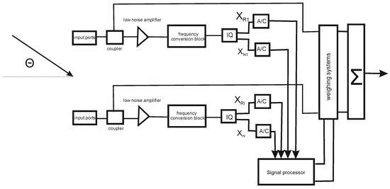
Figure 6.
Adaptive antenna system.
The system is composed of several components, the most important of which are:
- Antenna array;
- Microwave coupler systems;
- Frequency conversion block (there are solutions without frequency conversion);
- IQ metabolism systems;
- A/D converters;
- A signal processor based on an implemented algorithm for determining complex weights;
- Weighing systems.
The digital signal processing path consists of:
- A/D converters;
- One or two signal processors;
- Digital weighing systems.
The selection of parameters of each component affects the accuracy and speed of the adaptation process, which results in obtaining the desired directivity characteristics or determining the directions of incoming signals.
The adaptive algorithm uses information developed solely on the basis of:
- Output signal so (weigh-dither algorithm);
- sn input signals. (inversion-matrix algorithm);
- Signals so and sn algorithm (Applebaum–Howell’s and Widrow).
The key problem of ensuring the proper operation of the adaptive antenna is the algorithm for generating wm weights. This algorithm can be implemented in software or hardware. The algorithms used can be divided into two groups:
- With feedback;
- No coupling.
The basic feature of systems using uncoupled algorithms is the generation of wn scales only on the basis of input data and control of weighing systems with a small but finite error. The operation of such a system is not corrected by output signals, as is the case in systems with feedback.
All algorithms are based on two basic elements:
- Inverted covariance matrix of received signals sn;
- On the control vector.
The signal at the input of each element of the antenna array is a composite of thermal noise, signals of interfering sources and the desired signal in the antenna illumination zone FOV (field of view).
In a simplified form, we can write it as the following equation:
The goal of each algorithm is to generate weights that will result in the maximum reduction in the influence of interfering signals and the domination of the output signal by the desired signal. The basic operations of the algorithm are presented in Figure 7. The designed algorithm model is a mathematical model that graphically reflects the operation of the adaptive antenna array process in the base station of the mobile telephony system. It ensures the adaptation of the radiation characteristics of the antenna array to the changing situation in the sector covered by the antenna. The model was created based on formulas and expressions describing the LMS adaptive algorithm [24].
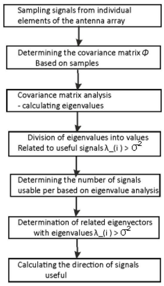
Figure 7.
Basic operations of the adaptive algorithm.
The useful signal used in the model is described by the following relationship:
where:
i-th useful signal received in the n-th array element;
amplitude of the i-th useful signal;
difference between the phases of the i-th signal received in two consecutive antenna components.
The phase shift is determined based on the given angle of arrival of the signal using the following relationship:
where:
is the angle of incidence of the i-th useful signal.
Interfering signals are described similarly.
The useful signal vector can be represented as:
and the interference signal vector as:
For the case of many useful and interfering signals, the signal vectors are as follows:
The covariance matrix of the useful and interfering signals is obtained from the following relationship:
Total covariance matrix:
where:
is the n by n noise covariance matrix.
where:
is the noise power.
The reference signal is described by the following relationship:
where:
is the amplitude of the reference signal;
is the amplitude of the reference signal with a random value.
Reference correlation vector:
The vector of weight coefficients is determined from the following relationship:
In order to obtain a graph of the antenna’s radiation power characteristics as a function of the scanning angle, we use the following relationship:
where:
x is the scanning angle ;
power radiated in the x direction;
an auxiliary vector specifying the signal parameters in the x direction.
where
is the phase shift between subsequent elements due to the value of angle x.
Using the Mathcad mathematical program, the possibility of directing the main antenna beam in the direction of the desired signal was examined [25]. Selected radiation characteristics of the eight-element antenna array, Figure 8, for signals coming from different directions are presented below (Figure 9, Figure 10, Figure 11, Figure 12, Figure 13).
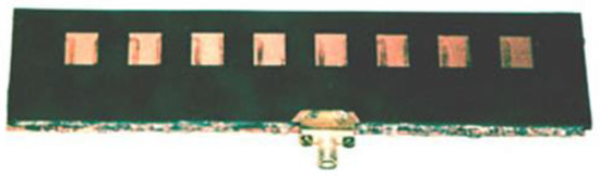
Figure 8.
Eight-element antenna array on a dielectric substrate: physical implementation.
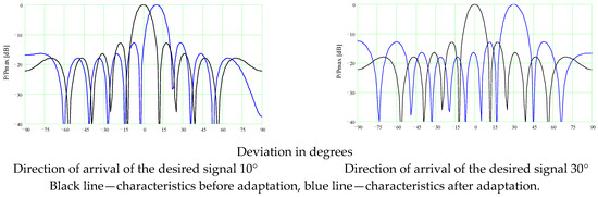
Figure 9.
Radiation characteristics of an 8-element array.
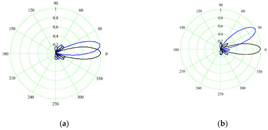
Figure 10.
Normalized directivity characteristics of an 8-element array before and after adaptation in polar coordinates. (a) The signal falls at an angle of 10. (b) The signal falls at an angle of 30°.
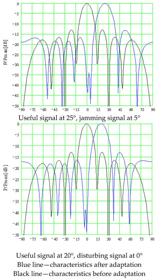
Figure 11.
Radiation characteristics of an 8-element array.
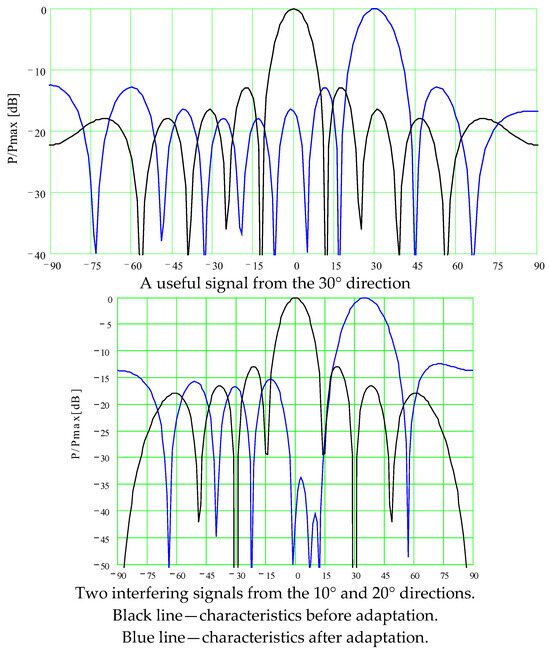
Figure 12.
Radiation characteristics of an 8-element array, black line.
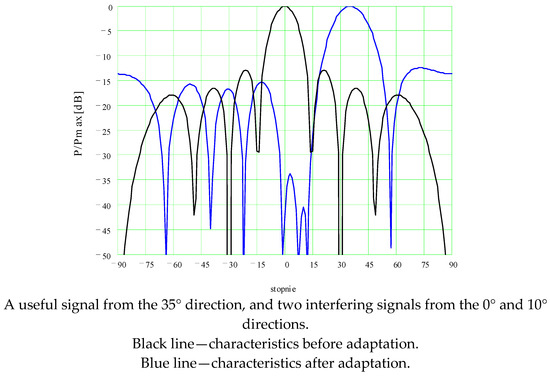
Figure 13.
Radiation characteristics of an 8-element array.
5. Conclusions
The use of adaptive antennas in mobile telephony systems allows the avoidance of the imperfections of using antennas with omnidirectional radiation characteristics in base stations. In modern mobile telephony systems in areas with high traffic density, base stations are used, consisting of a large number of adaptive sector antennas with a small sector angle (e.g., 12 antennas, each with a radiation sector of 30°). This results in more effective management of the allocated frequency range, which allows for the servicing a larger number of mobile subscribers at the same time. Moreover, the radiation characteristics of such sector antennas are more accurate and are characterized by low power emission values in undesirable directions.
The algorithm used is only a proposal that can be implemented in mobile telephony systems. It allows the problem of adapting the radiation pattern of an adaptive array to be solved based on the knowledge of the signals reaching the antenna. It is not required to know the angle of arrival of the useful signal, only its statistical parameters. For this reason, it is suitable for use in mobile telephony systems. In these systems, the exact location of the mobile station is not known, but it is known what the signal parameters are and in which time slot the signal will be transmitted.
This algorithm is also useful because it minimizes the radiation characteristics of the array in the direction of the disturbance. This phenomenon is particularly useful in very densely populated areas, where the distances between individual base stations are very small, which increases mutual interference between them. Moreover, in such areas there are usually several different networks operating, which may interfere with each other.
The proposed simulation model allows for a graphical illustration of the adaptation process of the adaptive antenna’s radiation pattern. It includes the presentation of changes in radiation characteristics as a result of changes in the location of mobile subscribers for a given number of subscribers served, as well as the directions and amounts of interference occurring. This model can be very easily configured for various assumptions, such as the number of active elements in the array, the number and locations of mobile stations and interference signals, the movement of mobile stations and interference signals, and their powers. Therefore, it can be considered universal for the issues of adaptive algorithms.
Funding
This research was funded by Military University of Technology, grant number [24 450].
Data Availability Statement
The data that support the findings of this study are available from the 363 corresponding authors upon reasonable request.
Conflicts of Interest
The authors declare no conflict of interest.
References
- Hubregt, J. Visser Array and Phased Array Antenna Basics; John Wiley & Sons, Ltd.: Hoboken, NJ, USA, 2005. [Google Scholar]
- Ekstrom, H.; Furuskar, A.; Karlsson, J.; Meyer, M.; Parkvall, S.; Torsner, J.; Wahlqvist, M. Technical Solutions for the 3G Long-Term Evolution. IEEE Commun. Mag. 2006, 44, 38–45. [Google Scholar] [CrossRef]
- Dahlman, E.; Ekstrom, H.; Furuskar, A.; Jading, Y.; Karlsson, J.; Lundevall, M.; Parkvall, S. The 3G Long-Term Evolution—Radio Interface Concepts and Performance Evaluation. IEEE Veh. Technol. 2006, 1, 137–141. [Google Scholar]
- Al-Afandi, J.; Horváth, A. Adaptive Gene Level Mutation. Algorithms 2021, 14, 16. [Google Scholar] [CrossRef]
- Series, M. Recommendation ITU-R M.2083-0: IMT Vision—Framework and Overall Objectives of the Future Development of IMT for 2020 and Beyond; International Telecommunication Union (ITU): Geneva, Switzerland, 2015. [Google Scholar]
- Gupta, A.; Jha, R.K. A survey of 5G network: Architecture and emerging technologies. IEEE Access 2015, 3, 1206–1232. [Google Scholar] [CrossRef]
- Kelner, J.M.; Ziółkowski, C. Impact of multi-beam antenna system on interference level in subscriber channel. Int. J. Electron. Telecommun. 2020, 66, 17–23. [Google Scholar]
- Valiente, G. Adjacency: Maps and Efficient Graph Algorithms. Algorithms 2022, 15, 67. [Google Scholar] [CrossRef]
- Oziewicz, M. The Application of MUSIC Algorithm to Time Delay Estimation in OFDM Wireless Channels. IEEE Trans. Broadcast. 2005, 51, 249–255. [Google Scholar] [CrossRef]
- Suchodolski, D. Linear antenna array with electrically shaped beam. Master’s Thesis, Faculty of Electronics and Information Technology, Institute of Radioelectronics, Warsaw University of Technology, Warszawa, Poland, 2003. [Google Scholar]
- Hawro, P.; Kwater, T.; Pękala, R.; Twaróg, B. Soft Sensor with Adaptive Algorithm for Filter Gain Correction in the Online Monitoring System of a Polluted River. Appl. Sci. 2019, 9, 1883. [Google Scholar] [CrossRef]
- Panwar, N.; Sharma, S.; Singh, A.K. A survey on 5G: The next generation of mobile communication. Phys. Commun. 2016, 18, 64–84. [Google Scholar] [CrossRef]
- Shu, T.; Xia, M.; Chen, J.; De Silva, C. An energy efficient adaptive sampling algorithm in a sensor network for automated water quality monitoring. Sensors 2017, 17, 2551. [Google Scholar] [CrossRef] [PubMed]
- Bubnicki, Z. Control Theory and Algorithms; PWN: Warszawa, Poland, 2005. [Google Scholar]
- Chai, T.; Draxler, R.R. Root mean square error (RMSE) or mean absolute error (MAE)?—Arguments against avoiding RMSE. Geosci. Model Dev. 2014, 7, 1247–1250. [Google Scholar] [CrossRef]
- Wnuk, M. Multilayer dielectrically periodic antenna structure in a cascade view. Appl. Sci. 2022, 12, 4185. [Google Scholar] [CrossRef]
- Sauter, M. From GSM to LTE-Advanced Pro and 5G: An Introduction to Mobile Networks and Mobile Broadband, 3rd ed.; Wiley: Hoboken, NJ, USA, 2017. [Google Scholar]
- Baek, M.S.; Kook, H.J.; Kim, M.J.; You, Y.H.; Song, H.K. Multi-Antenna Scheme for High Capacity Transmission in the Digital Audio Broadcasting. IEEE Trans. Broadcast. 2005, 51, 551–559. [Google Scholar] [CrossRef]
- Hawro, P.; Kwater, T.; Strzęciwilk, D. The monitoring system based on lookup algorithm for objects described by ordinary differential equations. ITM Web Conf. 2018, 21, 6. [Google Scholar] [CrossRef]
- Cormen, T.H.; Leiserson, C.E.; Rivest, R.L.; Clifford, S. Introduction to Algorithms; Wydawnictwo Naukowe PWN: Warszawa, Poland, 2018. [Google Scholar]
- Arora, S.; Barak, B. Computational Complexity: A Modern Approach; Cambridge University Press: Cambridge, UK, 2007. [Google Scholar]
- Ito, K.; Xiong, K. Gaussian filters for nonlinear filtering problems. IEEE Trans. Automat. Contr. 2000, 45, 910–927. [Google Scholar] [CrossRef]
- Bezanson, J.; Edelman, A.; Karpinski, S.; Shah, V.B. Julia: A fresh approach to numerical computing. SIAM Rev. 2017, 59, 65–98. [Google Scholar] [CrossRef]
- Ruhela, I.D.S.; Jat, I.R.N. Comparative Study of Complexity of Algorithms For Ordinary Differential Equations. Int. J. Adv. Res. Comput. Sci. Technol. 2014, 329, 329–334. [Google Scholar]
- Atallah, M.J.; Blanton, M. “Algorithms and Theory of Computation Handbook”: General Concepts and Techniques; Chapman & Hall/CRC: Boca Raton, FL, USA, 2010; ISBN 978-1-58488-822-2. [Google Scholar]
Disclaimer/Publisher’s Note: The statements, opinions and data contained in all publications are solely those of the individual author(s) and contributor(s) and not of MDPI and/or the editor(s). MDPI and/or the editor(s) disclaim responsibility for any injury to people or property resulting from any ideas, methods, instructions or products referred to in the content. |
© 2024 by the author. Licensee MDPI, Basel, Switzerland. This article is an open access article distributed under the terms and conditions of the Creative Commons Attribution (CC BY) license (https://creativecommons.org/licenses/by/4.0/).