1. Introduction
In the development of variants, prototypes, or small batches, the manufacturing processes and material groups that will be used later are usually already specified at the beginning of the product design process, as certain processes have proven to be optimal from experience and the know-how for them is available in-house [
1]. Especially in complex process chains consisting of multiple manufacturing and heat treatment steps, initial effort from planning to a robust process is high [
2], thus aiming for the conformity of new products with existing manufacturing processes. To achieve this, feedback of manufacturing knowledge into product development is necessary [
3,
4,
5]. Thereby, for the designers, the solution space for the component design during the development process is affected and substantially limited. The restrictions are determined to a large extent by the available manufacturing technologies as well as resources with their specific abilities [
6].
The necessity of multi-stage manufacturing processes has opened up a large solution space that must be explored during the design evaluation of the manufacturing conformity of a component. The challenge consists in the formalization of the manufacturing knowledge and the targeted solution space exploration for the components to be designed in order to allow for conclusions in the context of design for manufacturing on feasible product designs [
7]. This requires a holistic view of the subsequent process chains and the manufacturing sequences necessary to produce a component [
8]. In this way, not only process-specific but also cross-process manufacturing constraints resulting from the interaction of individual processes can be taken into account in the development [
9]. In order to implement a targeted solution space exploration, this article presents a constraint-based modeling strategy using the example of a multi-stage tailored forming process chain for manufacturing a multimaterial shaft in order to formalize manufacturing knowledge, such as the design of the manufacturing stages, cross-process manufacturing constraints or applicable manufacturing resources for product design and to make it available for product and process design decisions in the context of design for manufacturing. In this context, constraint-based process chain modeling is coupled with a case-based reasoning algorithm to represent complex process interactions. In addition, a conflict solver is implemented, which derives measures for the solution of violated manufacturing constraints.
2. Background
2.1. Tailored Forming
Tailored forming is a novel technology for the production of hybrid high-performance components. In contrast to other manufacturing technologies for solid multi-material components, a forming process takes place with previously joined semi-finished products so that two different materials are formed simultaneously. This has the advantage that, on the one hand, load-adapted material topologies can be achieved locally and, on the other hand, the joining zone can be influenced both geometrically and thermally during the forming process, resulting in a longer service life of the components [
10]. With the use of tailored forming, the number of necessary manufacturing steps usually increases, which also increases the complexity of the corresponding process chain [
11]. Complex process chains, such as that of tailored forming technology, are characterized by the fact that process uncertainties also increase in conjunction with the many interdependencies of the processes involved [
12,
13]. Therefore, the greatest possible conformity of product designs with later manufacturing restrictions of the process chain is particularly desirable [
14]. From a design perspective, multi-material design opens up great potential for new concepts in lightweight design [
15]. However, the handling of manufacturing-induced design constraints becomes more complicated due to the increased interdependence within the tailored forming process chain. The process-oriented design of the joining zone in particular takes a central role in the design of tailored forming components [
16]. The current challenge lies in the tailored forming process chain itself, which is being fundamentally researched for the first time in the Collaboration Research Center (CRC) 1153 for the manufacture of solid multi-material components. Therefore, cross-process manufacturing knowledge is in part only implicit. The development of tools for forming is especially complex and cost-intensive [
17]. Therefore, in addition to empirical investigations, research is increasingly using validated simulation models to develop knowledge about the tailored forming process chain. This knowledge is fed back into product development in the form of knowledge-based methods and tools to support the manufacturing-oriented design of tailored forming components and to make the complex technology applicable for design engineers [
18].
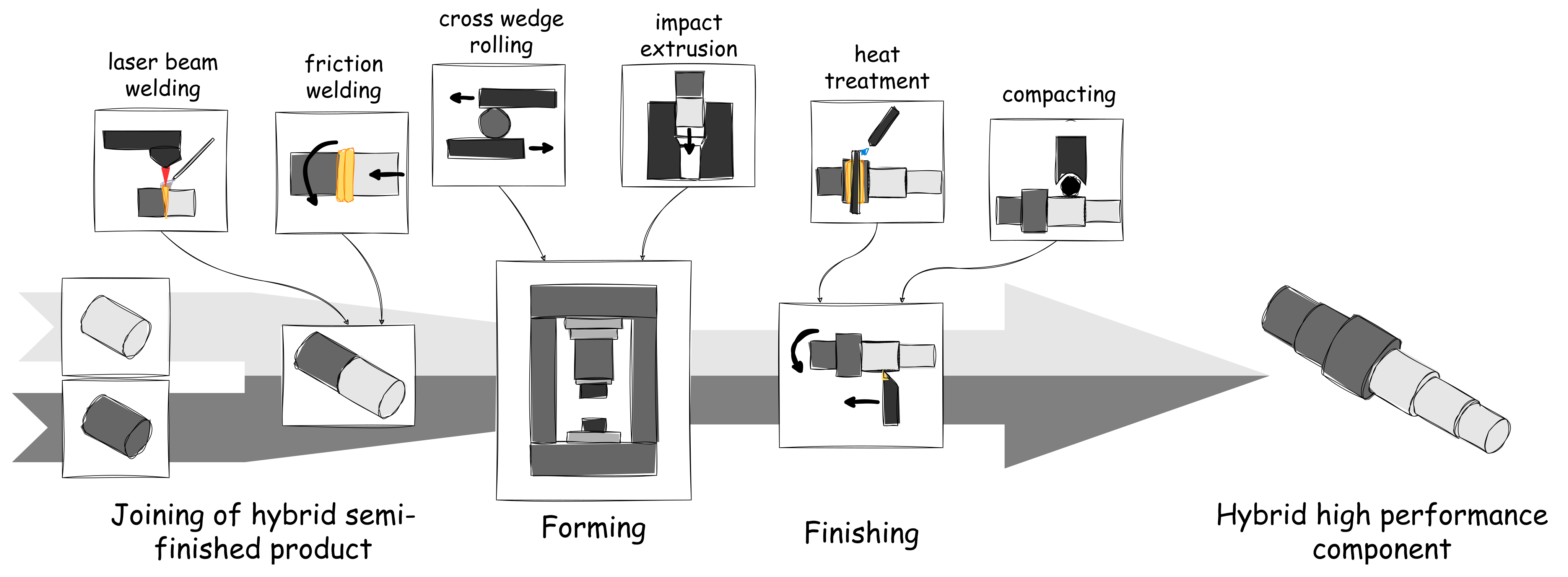
The tailored forming process chains investigated in CRC 1153 consist of three process areas [
16,
19]:
First, two monomaterial semi-finished products made of different materials are joined together;
This is followed by forming the hybrid semi-finished product. This produces structural changes that have a positive effect on the strength and service life of the components;
Finally, the shape and the edge zone and surface properties for the component are set by machining.
Within this process chain framework, various manufacturing processes are available for the production of a multimaterial shaft (see
Figure 1).
2.2. Including Manufacturing Knowledge in Product Design
In addition to, e.g., functional requirements, manufacturing processes determine the shape of a product and its components. Therefore, it is advantageous to consider this early in the design process [
21]. From a methodological point of view, design guidelines for various manufacturing techniques have been discussed for decades. These are available, e.g., as generalized collections of allowed and disallowed design snippets for a large set of single manufacturing processes, such as sloped surfaces that have never been drilled on or material accumulation in the casting [
22]. However, the exploration and limitation of the solution space for the product to be designed is dependent of the designer’s experience in instantiating these snippets on the current design task [
23]. Additionally, these snippets do not necessarily contain information about feasible geometric parameters as, e.g., traveling distances and achievable tolerances are machine specific data. Although individual development processes, such as axiomatic design [
24,
25,
26], integrate the process domain into their methodological framework, the developer is usually still forced to gather relevant information and negotiate the design in reviews with the manufacturing department [
8,
27]. Furthermore, especially in variant design, the question arises as to what changes are necessary to the existing production equipment in order to manufacture the new variant and, ideally, to minimize the effects of a new design on machining parameter changes and new CNC programs [
28].
In addition to methodological support, knowledge-based assistance systems can take into account concrete manufacturing resources and specific constraints, such as the above mentioned traveling distance of a NC axis [
29]. Because today’s computer-aided engineering environments offer plenty of capabilities to work with parametric designs and knowledge modeling, both analysis, i.e., checking a design for violations of manufacturing constraints, and synthesis, i.e., completing a design according to manufacturing constraints, are possible [
30,
31]. However, the manufacturing knowledge to be implemented must be made explicit and machine-readable [
23]. In general, there are many approaches to formalizing individual manufacturing processes and manufacturing process chains in the literature. Beside modeling single constraints, e.g., as value limits for dimensions in a CAD model, holistic approaches often use semantic information models, which are mainly based on the concept created by Martin [
32], which understands manufacturing as the sum of product, process, and resource. The process describes the sequences and procedures required to manufacture a specific product shape. The process thus describes the transformations of an operant during production. The product describes the component to be manufactured along a process chain. Since this is subject to different shape changes from process to process, an adaptive modeling is necessary here. The resources describe the production aids, tools, and machines that are used during production and thus determine the production capabilities and restrictions.
Within the manufacturing domain, many knowledge-based approaches can be used to formalize entire process chains explicitly and in a machine-readable manner. In doing so, they are able to derive inferences with respect to a process and process chain specification [
33,
34,
35,
36,
37]. However, these approaches are generally not suitable for design synthesis, where there is no feedback of analysis results into product design. Approaches from product development can map this feedback by investigating product designs using formalized manufacturing knowledge. Thereby, these models are able to show manufacturing conflicts and support their resolution by hints or direct product model adaptation [
38,
39,
40,
41]. In doing so, they usually focus on specific manufacturing processes and their sequences of operations and again cannot consider holistic process chains and different manufacturing processes. A formalism is missing regarding how entire manufacturing process chains can also be used for design synthesis. This leads to the research question: How can the process chain-oriented design evaluation of multi-stage manufactured tailored forming components be supported by knowledge-based assistance systems?
3. Challenges and Concept
In order to develop a knowledge-based assistance system for process chain-oriented design evaluation of multi-stage manufactured tailored forming components, two aspects need to be considered. On the one hand, the interrelationships within a multi-stage tailored forming process chain that lead to a specific component shape must be captured and formalized in the assistance system. On the other hand, a restriction check is required which, based on the formalized process chain relationships, compares the fulfillment of requirements of all involved manufacturing steps with the specification of a tailored forming component design and derives the possible needs for the action to achieve process chain conformity.
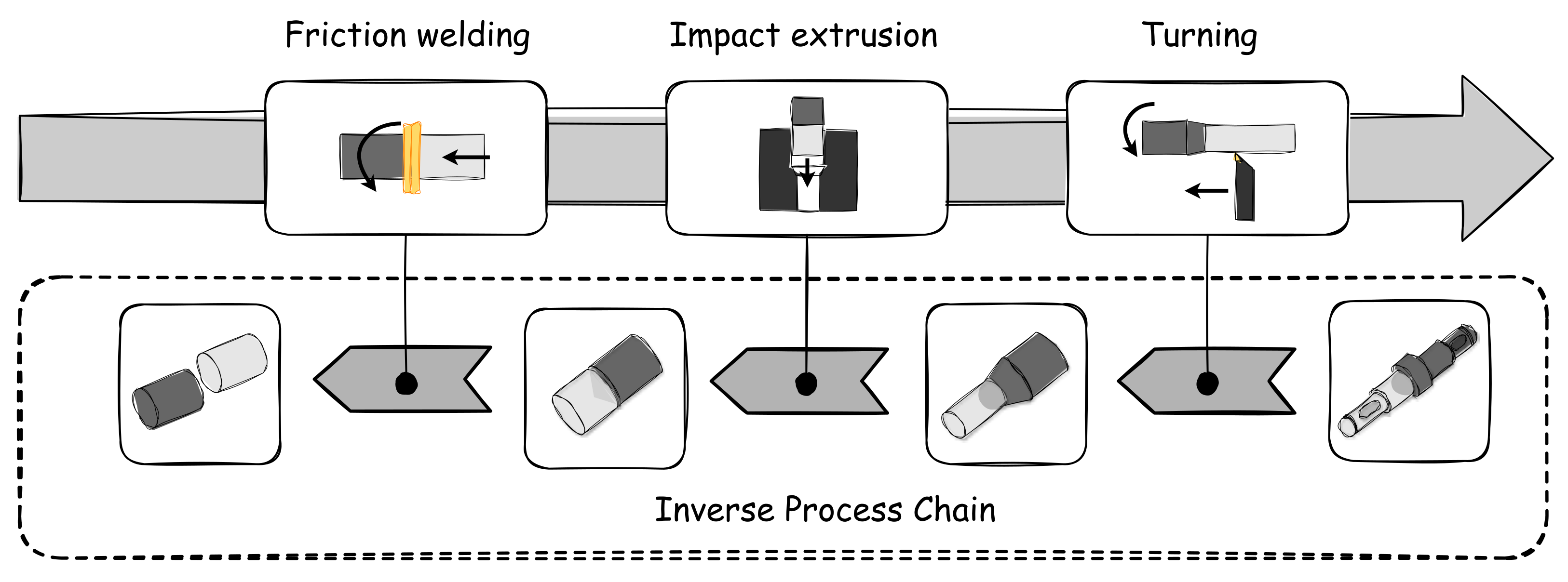
For this purpose, this paper proposes a manufacturing stage model which, starting from a predefined manufacturing process chain and a component design, derives the geometry models of the manufacturing stages required for production and simultaneously performs a restriction check. The idea of an inverse process chain representation is pursued (see
Figure 2), whereby the process chain is viewed against the actual process direction.
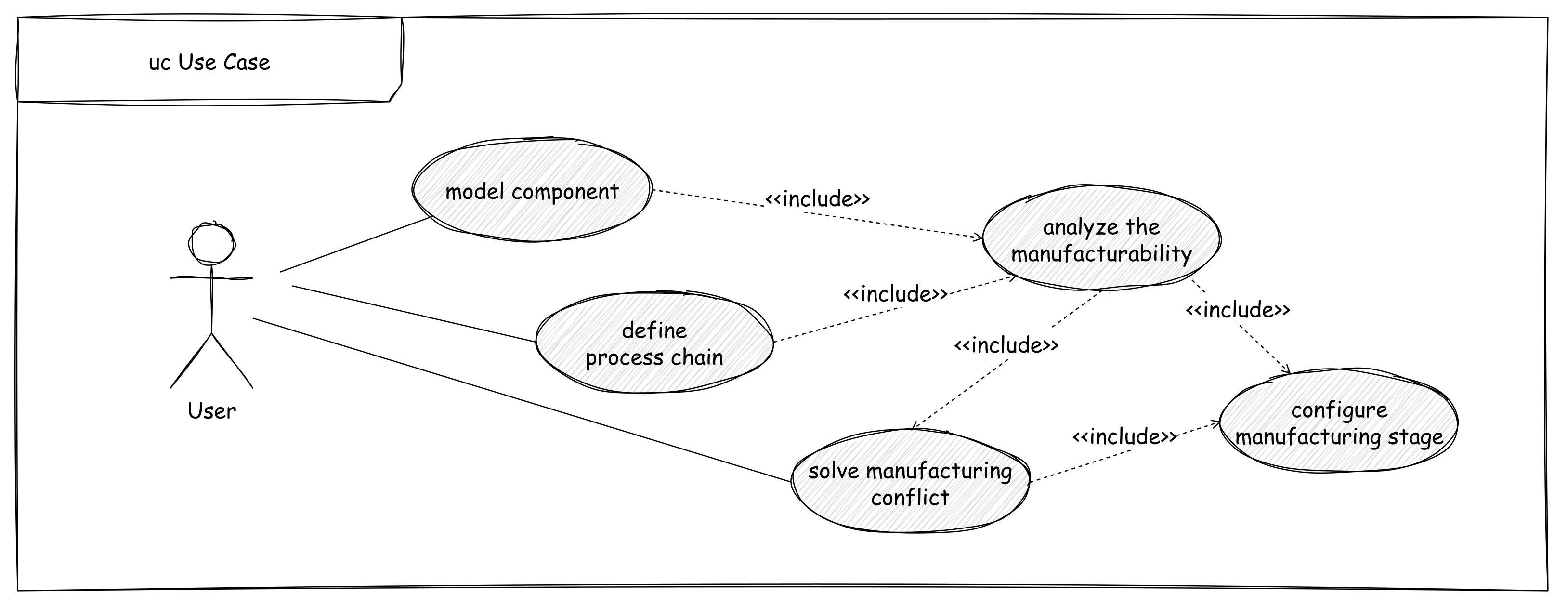
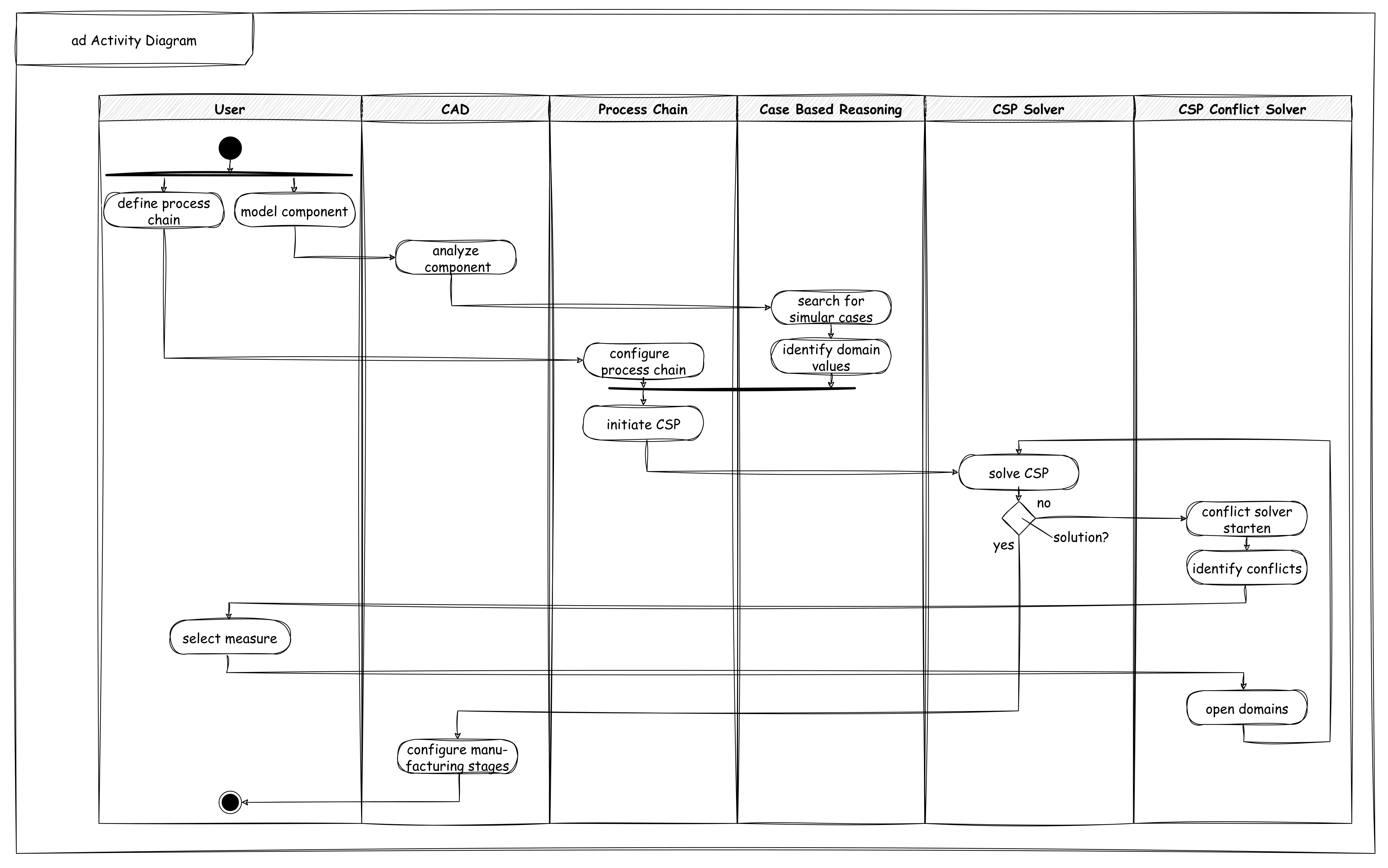
The activities required for this are shown in
Figure 3. At the beginning, the user models a component and also defines a process chain with which the component is to be manufactured. The user then checks whether the component can be manufactured by the specified process chain. If this is the case, the necessary manufacturing steps can be configured. If the component cannot be manufactured, suitable measures are suggested automatically for emerging conflicts.
The scientific goal is to support the intensive information exchange between product development and manufacturing planning by considering process chain knowledge in the component development via a knowledge-based approach, leading to a manufacturable component design. By using the holistic view of the latter process chain, the so-called process-cross manufacturing restrictions can also flow into the design department, which results from the interactions of all involved processes [
11].
The challenge in formalizing process chain knowledge is the abstraction of the process steps, since the tailored forming process chain is composed of different manufacturing processes. This requires the identification of a common abstraction level so that all processes can be represented in one model. This is compounded by the data situation and the level of knowledge of tailored forming technology, the scope of which is currently still comparatively small. Therefore, the manufacturing knowledge is partly only implicitly available and the access from real test and simulation data is limited. To address these challenges, Herrmann et al. [
42] present a concept in which process knowledge is formalized in a model-based way via numerical process simulations. Thereby, the reasoning mechanism is implemented iteratively via several analysis-synthesis operations, which enables inverse process modeling and the derivation of manufacturing stages. However, this modeling of the manufacturing stage model has drawbacks. On the one hand, the modeling strategy requires a high implementation effort and results in a complex model structure. On the other hand, the iterative use of numerical simulations requires a large computing time. Furthermore, the existing approaches of the manufacturing stage model lack the aspects of how to detect possible manufacturing conflicts and how to derive measures to achieve manufacturability.
In this article, the process chain is understood as a configurable design object, where sequencing (routing the component through the process chain) and parameterization (assigning process parameters) result in a process chain variant for the desired component. If both are modeled within discrete domains, the process chain can be represented as a configuration problem, which can be implemented via a Constraint Satisfaction Problem (CSP). A CSP is a task in which a finite set of variables is represented by finite domains (allowed range of values). In addition, a finite set of constraints is formulated, which limits the value assignment of the variables between each other. Suitable constraint solvers can also investigate whether a variable assignment that satisfies all constraints exists [
43,
44,
45]. The CSP has the advantage that a test geometry can be applied to the constraint net in order to check the producibility of a variant. Furthermore, a portfolio of capabilities for a given process chain variant can be output and made available to the designer. Starting from the design geometry of a tailored forming component, a valid configuration is searched for all process-involved manufacturing stages, taking into account manufacturing constraints. If at least a solution is found, the design geometry is suitable for the process chain and complies with all manufacturing constraints. The CSP as a modeling tool promises high performance, automatability, and extensibility due to its underlying configuration mechanism [
46].
4. Constraint-Based Process Modeling and Reasoning
This section shows the modeling of process chains by coupling a domain concept with a constraint network. Based on this constraint-based knowledge modeling, a reasoning mechanism is presented that can evaluate the manufacturability of a component and configure the necessary manufacturing steps. The modeled contents are individual and depend on the considered component and its process chain. Nevertheless, the modeling process can be methodically supported by central steps. A basic orientation for this methodology offers a recommendation after Stokes for the development of knowledge-based technical applications with the emphasis in the phases of the MOKA life cycle: capture, formalize, and package [
47]. In the following, this procedural model is summarized in the three steps of Knowledge Survey, Knowledge Modeling, and Knowledge Processing.
The formalization of a process chain begins with knowledge acquisition. This requires the acquisition of all input, intermediate and output products involved in the process chain, process-specific manufacturing capabilities (in the CRC, especially the material combinations) and restrictions, as well as available manufacturing resources. How this information and knowledge is obtained again depends on the use case and the existing information sources. In general, interviews with experts and the analysis of manufacturing databases, such as resource planning systems, as well as machine data sheets, offer an efficient method to gather this knowledge. Within the application example, expert interviews were conducted and information was extracted from a CRC 1153 internal research data and knowledge management system. The knowledge management system is used to coordinate the exchange of information and knowledge across processes within the CRC. In the process, relevant information about processes and resources is semantically annotated and made available collaboratively.
A process chain is created by stringing together several individual processes. Each process has input and output products that represent the links within the process chain. In manufacturing, these products are the individual production stages. Thus, a process chain represents a graph. This basic idea is taken up at this point by modeling the geometric transformations of the manufacturing stages by a single process as edges in the form of constraints and descriptive shape parameters of the manufacturing stages as well as transformation-influencing process parameters as nodes by variables with a specific domain. At this point, an abstraction and thus a lower resolution of the manufacturing processes is deliberately accepted in order to achieve a common level of abstraction within the process chain. If an abstraction is not possible for certain processes, it is also possible to use external surrogate models (see
Section 5). Here a modular structure is followed, which groups all variables, domains, and constraints, which are assigned to a single manufacturing process, within the process containers. These process containers thus represent an abstraction of the capabilities of the respective process, e.g., resource-related manufacturing restrictions, achievable process windows, and available tools. In addition to the processes, the manufacturing stages are also important artifacts for describing a process chain, since they are the interfaces between the process containers. To formalize these interfaces, the manufacturing stages are explicitly annotated with specific geometry domains based on the variables. This geometric description can later be translated into three-dimensional CAD models via a link to a design system. The manufacturing resources significantly constrain the process capability and thus the feasible transformation of the manufacturing stages. The resources can also be formalized via characteristics. Limiting process parameters, such as a maximum weld-through thickness or formable diameters, are annotated via variables with a specific domain and linked to the geometry parameters of the manufacturing stages via constraints. These domains are defined by the available machinery and tooling. This modeling concept thus allows for the integration of the three artifacts—product, process, and resource—within a CSP.
To enable the subsequent reasoning process (see
Section 6), the modeling of the constraint network within the process containers follows a fixed scheme. When modeling constraints, CSP distinguishes between hard and soft constraints. Hard constraints represent the geometric transformations and physical or process-related restrictions that must not be violated. Thus, hard constraints define fixed limits for the manufacturable solution space for a precast geometry as the set of all possible manufacturing stage configurations. The soft constraints represent target requirements with which this solution space can be additionally restricted, starting from the available manufacturing resources. To model a process, the shaping characteristics of two successive manufacturing stages are linked via explicit binary hard constraints or higher order hard constraints. In this process, the shape change of the manufacturing stages can be modeled. The CSP must be designed in such a way that the consideration of all hard constraints results in at least one valid solution. In order to investigate the manufacturing suitability of the manufacturing stages, additional geometry-restricting manufacturing constraints are formalized within the process containers as binary soft constraints related to the manufacturing stages to be restricted. The soft constraints consist of a product-related (left side of the constraint) and a resource-related (right side of the constraint) side. At this point, resource-related manufacturing capabilities are integrated with available manufacturing resources. In addition to the soft constraints, potential costs for the purchased production resource are also stored, which arise in the case of a new procurement or adaptation. This later allows for a cost-oriented specification of manufacturing resources to achieve the manufacturability of a component.
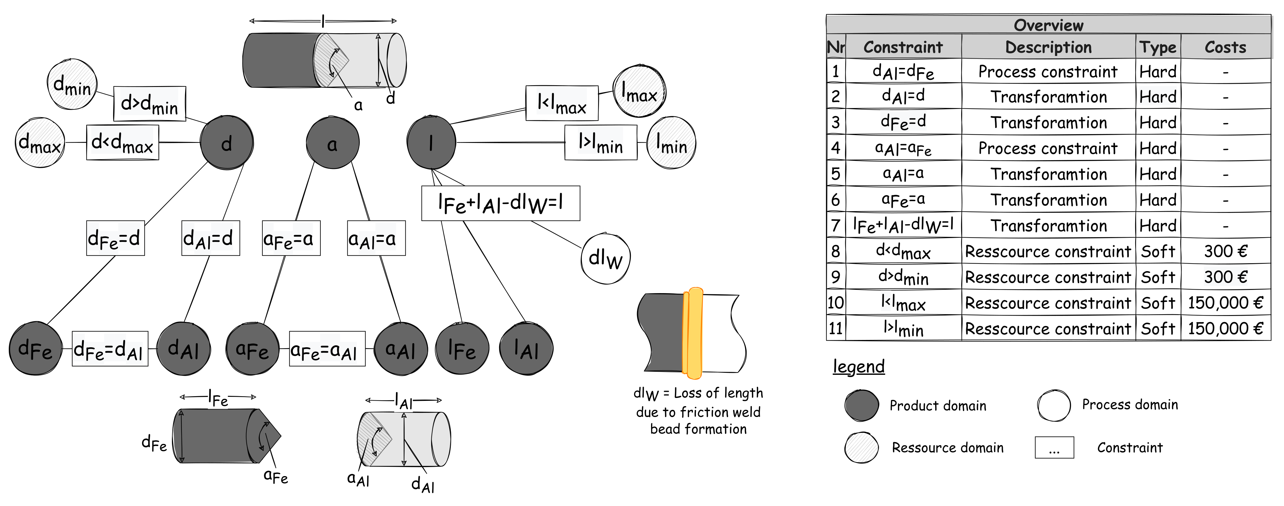
Figure 4 shows the modeling for the process container of a friction welding process to produce a multi-material semi-finished product.
The modeling of the CSP can be done by three steps:
Parameterization of the manufacturing stages as well as manufacturing resources and creation of product and resource domains as variables;
Formulation of the geometric transformations of the manufacturing stages as well as process-related constraints as hard constraints;
Inclusion of resource-related geometry constraints as soft constraints and deposit of costs for the respective manufacturing resource.
The difficulty in modeling the constraints is the interacting behavior of the constraints to each other. Therefore, it is important to understand and consider the interactions between the constraints.
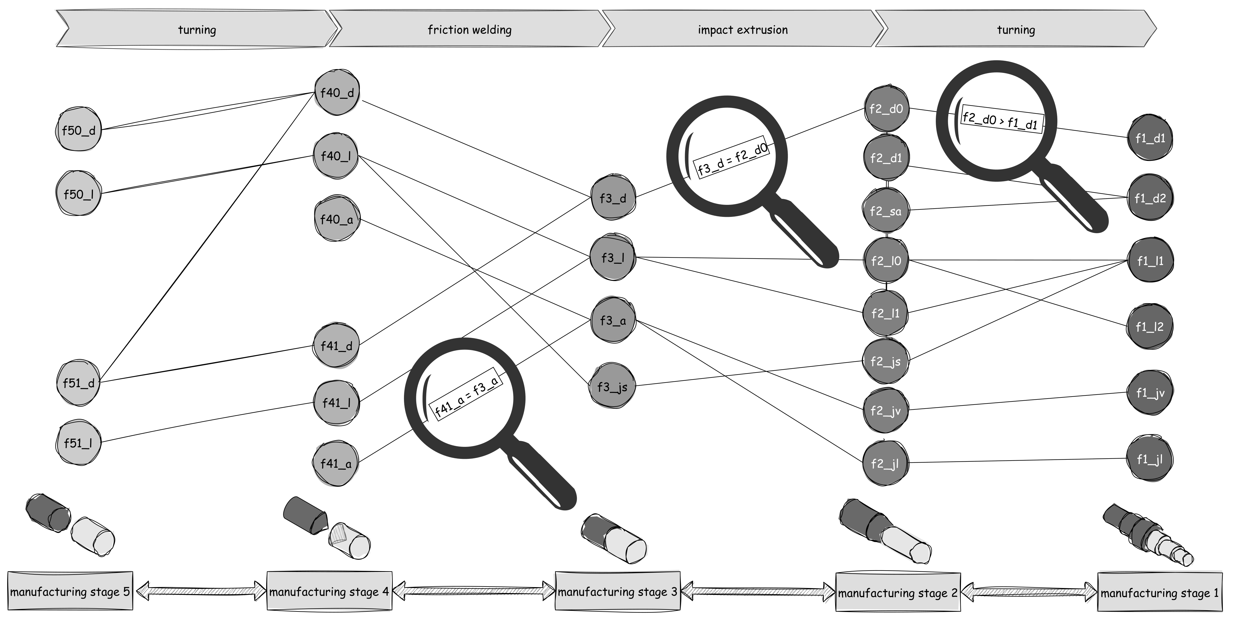
By linking the process containers to each other via the manufacturing steps, an entire process chain can be explicitly modeled. With reference to the application example, a serially joined tailored forming shaft is manufactured through four process steps:
At the beginning, two monomaterial semi-finished products made of different materials are machined by turning to obtain a pointed joining zone;
This creates a larger friction surface in the subsequent friction welding process and thus strengthens the bond;
Subsequently, the hybrid semi-finished product is thermo-mechanically formed into a preform by an extrusion process;
Finally, the formed blank is machined to the final contour to adjust edge zone as well as surface properties for the part [
16,
19].
The concatenation of these four process containers into a process chain within a constraint network is shown in
Figure 5.
Once the constraint network with all involved processes is modeled, CSP-specific consistency techniques and search algorithms can be used as an inference engine to search for a valid parameter combination for all manufacturing stages. Backtracking-based search algorithms are suitable for solution search. If at least one solution is found, the investigated component does not violate any manufacturing restrictions and can be manufactured with the existing process elements and resources. In return, it is also possible to derive measures by a conflict solver if no valid solution can be found (see
Section 6).
5. Modeling Complex Manufacturing by Using Case Based Reasoning
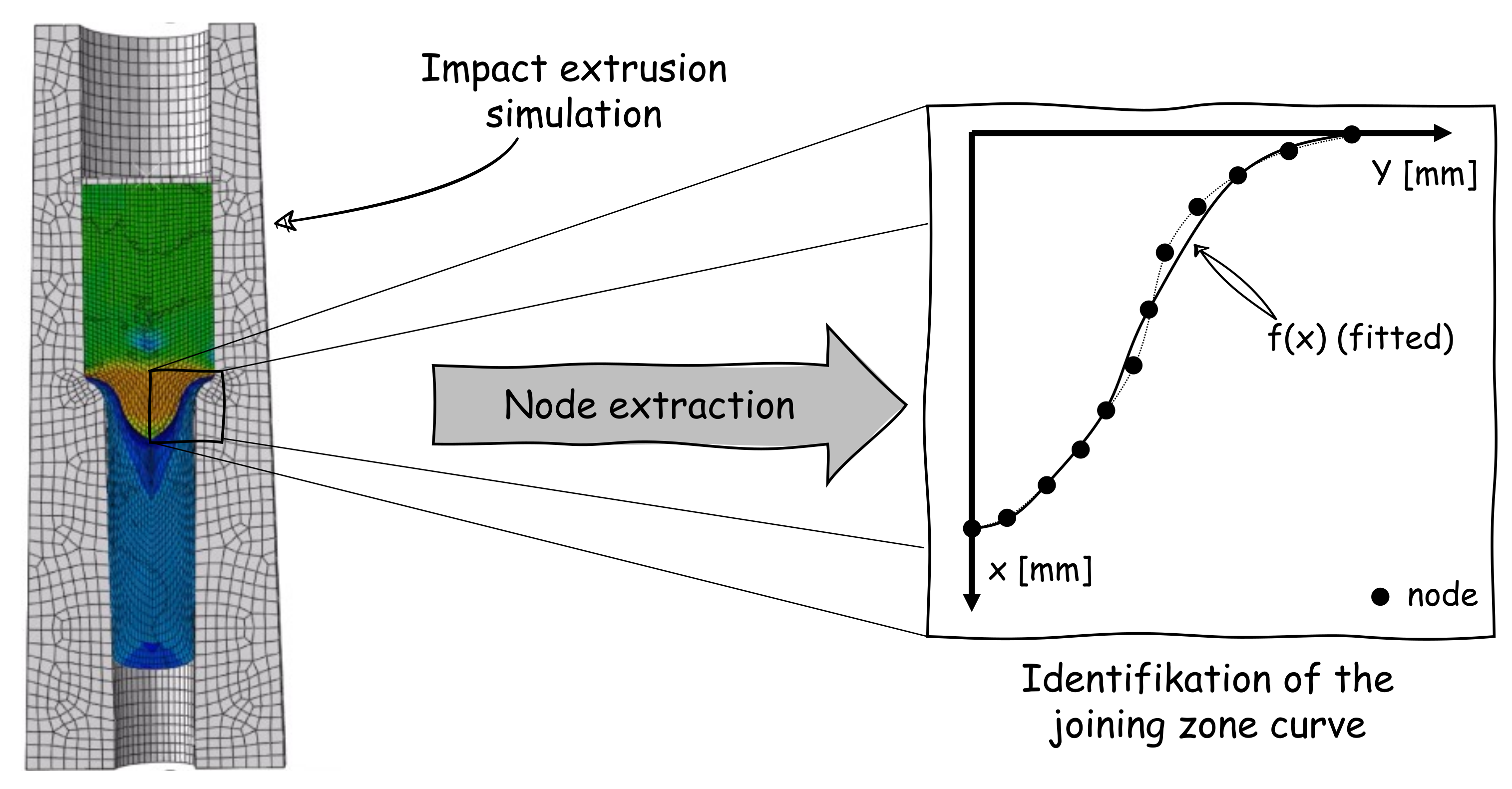
Manufacturing processes, such as a forming process, sometimes exhibit complex manufacturing interactions that cannot be formalized directly by analytic relationships in CSP via constraints. In this case, external surrogate models (e.g., finite element models) must be used to model the process interactions. Since the use of process simulations is usually associated with a high computational time, the following section presents the structure of a case-based inference logic using the example of the joining zone expression of an extruded tailored forming shaft. This inference logic allows external surrogate models to be incorporated into the CSP in order to restrict the domains for individual variables in the CSP to process-conformant value assignments in advance. The joining zone in the case of a multimaterial component is the area where the different materials of the component are joined together. In the case of the extruded tailored-forming shaft with serial material arrangement, the inner part of the joining zone is made of steel and the outer part of aluminum (see
Figure 6). The geometry of the joining zone of a tailored forming shaft is significantly influenced by the impact extrusion process. The main factors influencing this are the geometry of the previously joined surface
(e.g., flat or pointed), the degree of forming
, the shoulder angle of the extrusion die
, and the process parameters
(e.g., temperature or back pressure) [
48]. In order to obtain the knowledge about the forming behavior of the joining zone, parameter studies are carried out in advance with the aid of a finite element simulation of the impact extrusion. The main influencing factors are varied by means of a full-factorial experimental design and the expression of the joining zone is analyzed after the impact extrusion simulation. In order to formalize the results of the parameter study and make them available by computer, the geometry of the joining zone must be described mathematically. For this purpose, Siquera et al. [
49] derived a 2D functional profile f(x), which gives the surface of the joining zone by a complete rotation and covers a wide range of expression shapes.
This function is given by three physical parameters: Length
L, Radius
R, and Volume
V. Here, the starting point is at
, where R is the radius of the shaft at the given interface, and the end point is at
, where
L is the length of the joining zone. The volume
V corresponds to the volume enclosed in the joining zone (see
Figure 6, right).
With this mathematical modeling, the simulated joining zones can now be described by the parameter length
L, radius
R, and volume
V. These parameters can be identified by curve fitting, in which a curve is placed through the finite element nodes of the resulting joining zone. The Python library SciPy was used for this (see
Figure 6).
Figure 6.
Joining zone curve fitting from a finite element simulation of a impact extrusion process.
Figure 6.
Joining zone curve fitting from a finite element simulation of a impact extrusion process.
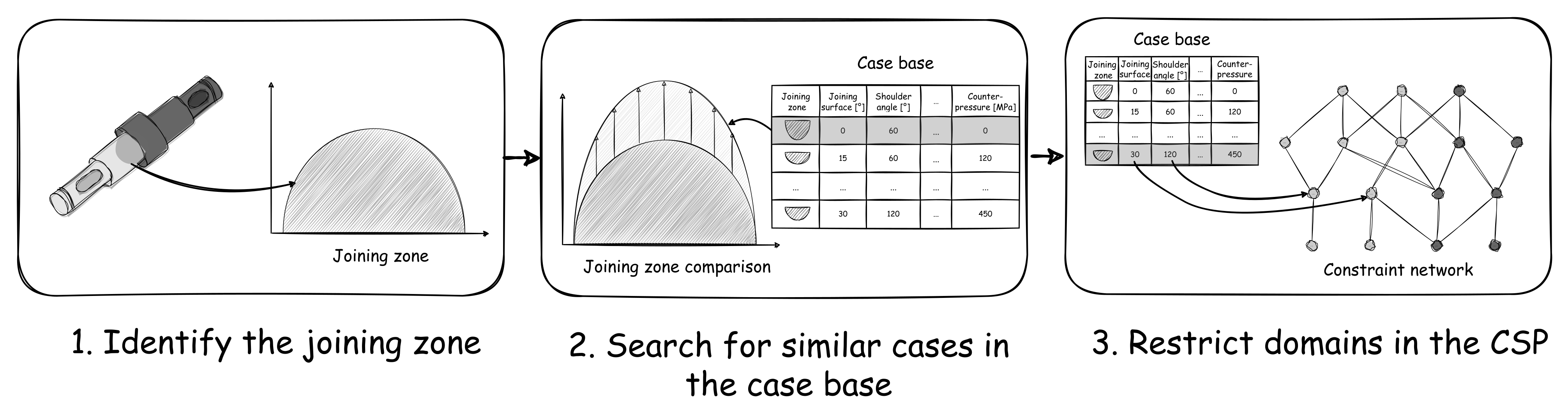
These parameters are then merged with the input variable that led to this joining zone expression in a tabular case base. The case-based reasoning logic works in three steps (see
Figure 7):
At the beginning, the joining zones are read out from the component to be examined. Since this is already modeled parametrically in the CAD model via the function (
1), the parameter length
L, radius
R, and volume
V can be read directly from the parameter set.
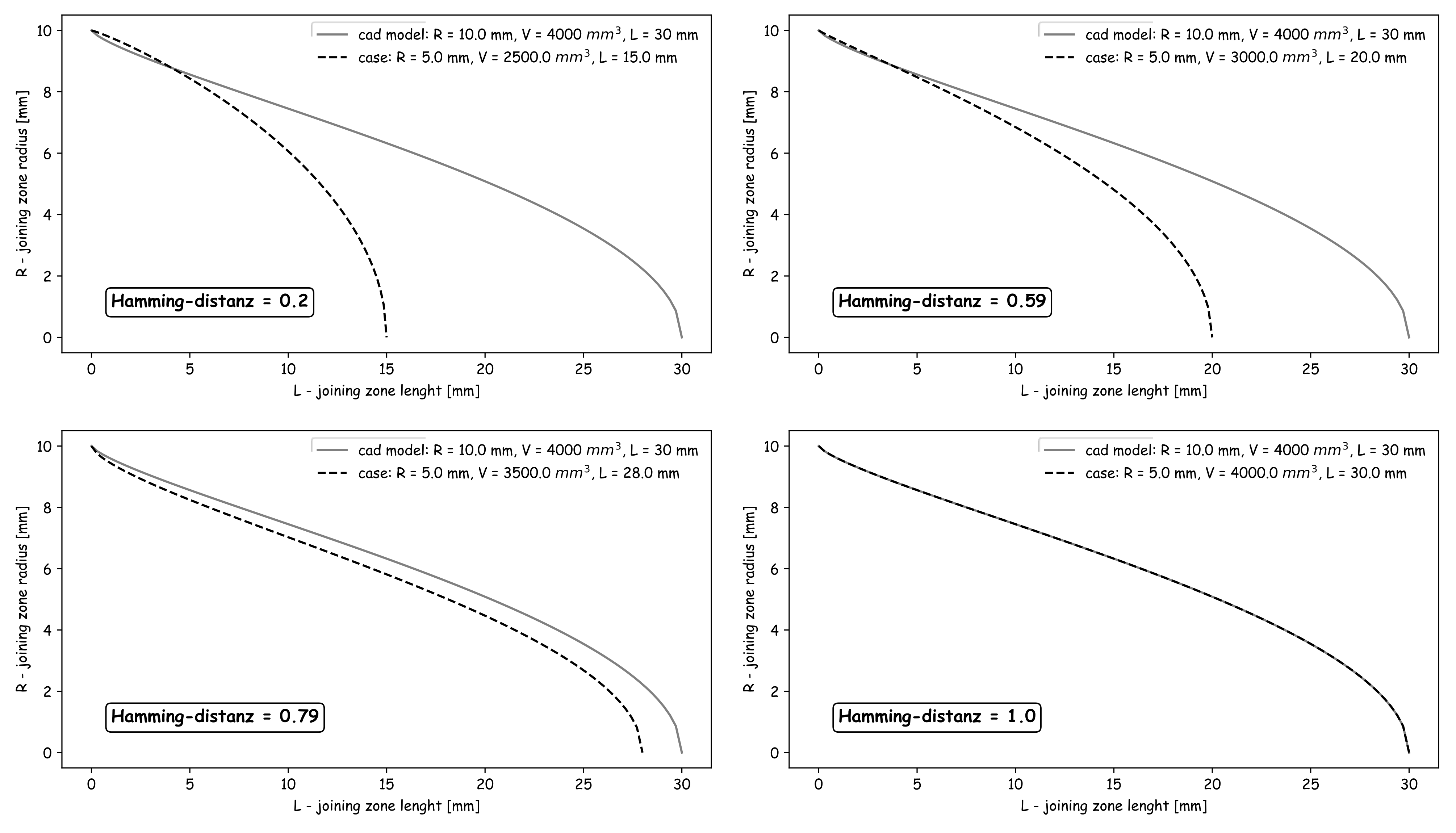
This parameter set is compared with the joining zones from the case base to identify similarcases (see
Figure 8). For this purpose, the joining zone profiles of the investigated component and the simulated case are discretized by 100 points. Here, the definition range is
, where
and
are the respective joining zone lengths of the studied component and the simulated case. To determine the similarity between the two discretized profiles, the Hamming distance is calculated according to Equation (
2) [
50]:
where
is the similarity measure,
and
are the point coordinates of the discretized profiles in y-direction,
is a weighting value, and
N is the number of points considered. In the present work, a non-weighted approach is used at this point, where all values of
are equated and removed from the formula. This procedure is repeated through a loop for all entries in the case base.
Finally, the case with the highest similarity value
is selected and transferred to the impact extrusion process container. Within the impact extrusion process container, the geometry of the previously joined surface
, the forming degree
, and the shoulder angle of the impact extrusion die
, among others, are formulated as variables. These variables could now be identified by case-based reasoning and must be provided to the constraint network. There are two ways to do this. On the one hand, additional soft constraints can be formulated, which require an equality condition between the identified parameters and the variables created in the process container. This has the advantage that the soft constraint is taken into account in a possible conflict search (see
Section 6). On the other hand, the identified parameters can be inserted directly into the domains of the variables. Thus, there is an advantage in terms of computation time, since the possible solution combinations are restricted in advance. However, these variables cannot then be considered in the conflict search. In this paper, the second option was used. With this three-part approach, it is now possible to consider the knowledge from a case base within a CSP.
Figure 7.
Approach for case-based reasoning.
Figure 7.
Approach for case-based reasoning.
Figure 8.
Comparison of different joining zone curves.
Figure 8.
Comparison of different joining zone curves.
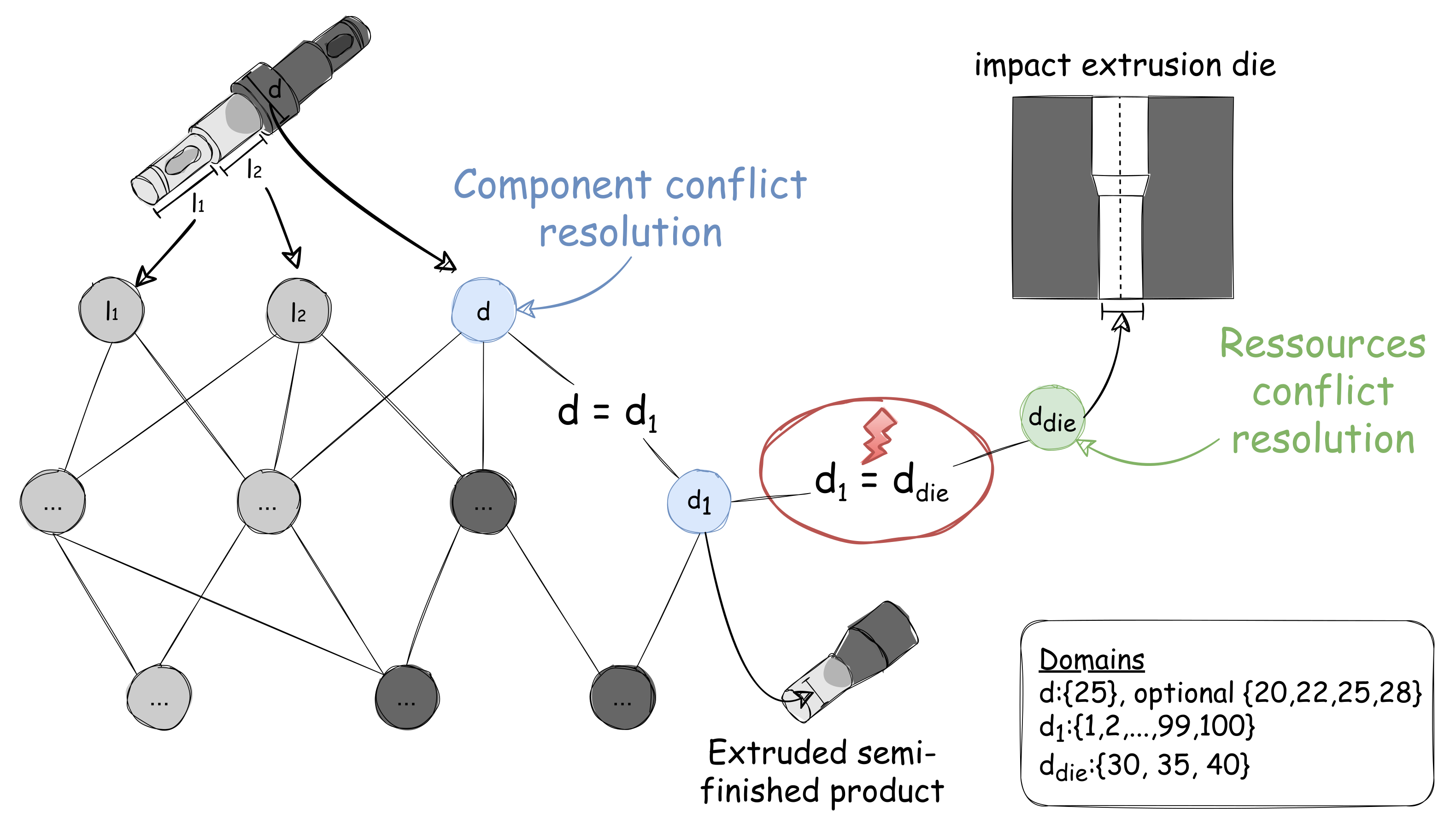
6. Handling of Manufacturing Conflicts
Up to now, it has been assumed that the constraint network can be resolved and a satisfactory parameter combination can be found for all production stages. If this is not the case, measures have to be taken to achieve a process chain conformity of the investigated component. Based on the requirement that the constraint network must have a solution considering all hard constraints, it can be concluded that at least one soft constraint is violated during the solution search and one of the manufacturing resources does not allow for manufacturability. To get to the root of the problem, the first step is to identify the violated soft constraints and, equivalently, the associated manufacturing resources through a relaxation process. During the solution process, one or more soft constraints are suppressed and it is examined whether a solution can be found by suppressing them. If a valid solution is found after the suppression, it can be implicitly concluded that the suppressed soft constraints or the manufacturing resources formalized behind them restrict the solution space in such a way that a manufacturability of the examined finished part geometry is not given. The necessary relaxation logic is implemented in a separate object class. The constraint relaxation class identifies all soft constraints and creates a list of all combinations of soft constraints to be suppressed. For each of these combinations, a separate solution process is started by the CSP solver to examine which combination of suppressed soft constraints are violated in the solution process. Since the solution processes of the combinations run independently, the computation time is reduced by running the solver processes in parallel (multi-threading). The solution finding is done by the CSP solver class. If a solution can be found, the violated soft constraints are identified. Conflict resolution makes use of the bidirectionality of constraint nets. This enables undirected reasoning. For the CSP this means that it does not matter which variables are resolved. In addition, the structure of the soft constraints follows a fixed scheme as the left side of the (un)equation always contains a component-related variable and the right side only contains a resource-related variable. As a result, there are now two ways to trigger a conflict. On the one hand, the component can be adjusted with respect to the production resource or the production resource is adjusted with respect to the component. Whether an adjustment is carried out on the part side or on the resource side is currently decided by the user. In the future, however, the aim is to make this decision automatically by calculating and analyzing possible solutions in advance and evaluating them by means of a cost- or effort-oriented weighting. In the following, using the example of a violated soft constraint, which requires equality between the formed diameter of an extruded semi-finished product and a deposited extrusion die, the process of a component- and resource-side conflict resolution is presented, in which the degrees of freedom in the CSP are increased and thus the solution space for unresolvable manufacturing constraints is enlarged (see
Figure 9).
6.1. Component-Based Conflict Resolution
Due to the serial arrangement of the process containers, the input parameters are known from the component under investigation. First, the user is given the option to declare the geometric input parameters as fixed or variable values. The latter can optionally be assigned limits or a set of discrete values (e.g., standardized diameters for bearing seats) as a defined variation space. Subsequently, if no solution of the CSP is found for the original input parameters that satisfies all the manufacturing constraints of the process chain, the specified variation spaces of the input parameters are first included by the CSP. If a solution still cannot be found by this extension of the solution space, in the second step, starting from the violated soft constraint, a path search is used to infer the causative input parameters. If these are marked as a variable, the number of nodes over which the connection exists (connection degree) and which neighborhood relationships exist in the part geometry model are recorded in addition to the connection. A rule-based reaction mechanism is implemented in order to be able to automatically explore further, and not previously defined, variation spaces in the component design. This prioritizes the input parameters according to their degree of connection in an ascending order, taking into account the neighborhood relationships in the geometry model, defining the subsequent parameter variation in each case by replacing the discrete input parameter with an opened value domain. With this opened domain, the solution process is restarted via the CSP solver. If this value range extension leads to a solution of the CSP, a corresponding model adaptation of the precast geometry is suggested to the user, which can be adopted in an automated way by a direct connection to the CAD model of the component. If the extension does not lead to a solution, the next adjustment is made from the reaction pool. Finally, the user must manually check the conformity of the modified precast geometry with regard to all requirements (especially functional safety).
In the example, the procedure looks as follows. By relaxing the constraints, a violated soft constraint with the equation could be identified and thus also the component-side variable . This represents the formed diameter of the extruded semi-finished product. Now the input parameters that influence the variable the most are searched for, i.e., which have a low degree of connection. In this case, this is the input variable d, which represents the diameter of a bearing seat on the part and is connected to by the upstream hard constraint . This variable was initially set by the user to d = 25 mm and does not yield a solution to the CSP. However, at the same time, an optional variation space of was assigned to the variable. The variable d is now added to the reaction pool. Since this is the only measure in the reaction pool, the reaction mechanism starts to replace the initial domain of with the variation space of and starts the solution search. However, no solution is found here either, since the matrix requires a diameter of . At this point, the domain of d is further opened to . With this domain open, the solution process is restarted and the CSP solver will configure the variable to d = 30 mm, d = 35 mm, or d = 40 mm. With the user’s approval after a functional safety check, the reaction pool passes the adjustments directly to the CAD model, which is provided to the user in an adjusted form. The example was used to present the procedure for component-based conflict resolution based on a violated soft constraint. It should be noted at this point that this procedure also works for several or combined violated soft constraints by including them in the reaction pool. This results in several options for resolving the conflict, which must then be evaluated by the user or a suitable heuristic.
6.2. Resource-Based Conflict Resolution
Resource-based conflict resolution follows a similar scheme as component-side conflict resolution. Here, the reaction pool consists of all violated soft constraints and violated soft constraint combinations. Since each soft constraint is also assigned potential costs for the production resource in question, which arise when a new resource is procured or adapted, the soft constraint combinations can be evaluated on the basis of their costs and the most cost-effective one can be selected. The reaction mechanism reads out the associated resource-related variables for these soft constraint combinations, opens their domains and, via a further solution process, determines the domains that enable the production of the component under investigation. This means that the related manufacturing resources are separated from their variables and the respective feature of the manufacturing resource can now be reconfigured by the CSP solver.
This procedure is again illustrated by the example. The user again requests a bearing seat diameter of d = 25 mm. Here, the soft constraint is violated again, since only the three die diameters are available. Since only one soft constraint is violated, the cost consideration is omitted at this point and the reaction mechanism opens the domain of the resource-based die diameter with . With this domain open, the solution process is restarted and the CSP solver will configure the die diameter to = 25 mm. This adjustment of the soft constraint results in the need of a new or adjusted manufacturing resource to produce the investigated part. Through a CAD link, the new impact extrusion die can then be exported as a CAD model through a previously created parametric geometry template and made available to downstream manufacturing planning for process specification.
7. System Architecture and Implementation
The system architecture and implementation of a knowledge-based system are crucial to create a robust and reliable assistance system. In this context, Python is one of the preferred programming languages because it is used by many developers, it allows for the integration of a large number of external libraries, and it has an interface to commercial CAD systems. Therefore, the entire system is computer-implemented in Python. To describe the system architecture and implementation,
Figure 10 lists the activities for implementing the manufacturing stage model in a flowchart. Here, the user starts by manually building a CAD model for the tailored-forming part under investigation. At the same time, the user defines the manufacturing process chain with the part shape and specifies which process steps form the process chain in which order. The user interacts via a web-based interface hosted on a Flask server [
51], which enables a user-friendly deployment within the development process.
Based on this, a CAD module examines the geometry model of the tailored-forming component under investigation and reads out the relevant geometry parameters as well as the joining zone design. For this purpose, the CAD system Autodesk Inventor is used, since this system has an extensive interface that can be controlled with Python. Alternatively, other CAD systems can be used that have a similar interface. The joining zone information is then provided to a case-based reasoning module. This module searches for similar designed joining zones within an empirical or simulated case base and identifies feasible value assignments for some domains. With this and the previously defined process chain, the process chain configuration problem is built as a CSP within a process chain module. For this, the necessary variables with their domains as well as the constraints are created in the CSP and the domains are set according to the results from the case-based reasoning. The initiated CSP is then solved with a CSP solver module. This module considers different algorithms for constraint propagation and solution search. If a solution is found that satisfies all constraints, the identified value assignments are returned to the CAD module. By linking to the CAD system Inventor, the configured manufacturing steps can be modeled and made available to the user as a download via the Flask interface. If no solution is found by the CSP Solver module, the CSP Conflict Solver is activated. It identifies the conflicting constraints and resolves these conflicts by opening the domains of the involved variables either on the resource or on the component side. This expands the solution space and CSP Solver module starts solving the CSP again. The decision of whether to solve on the component or resource side is made by the user. The domains can also be opened step-by-step to avoid high computation time in case the domains are too large. This process for conflict resolution can be performed several times to identify alternative solutions. After the program flow was introduced with
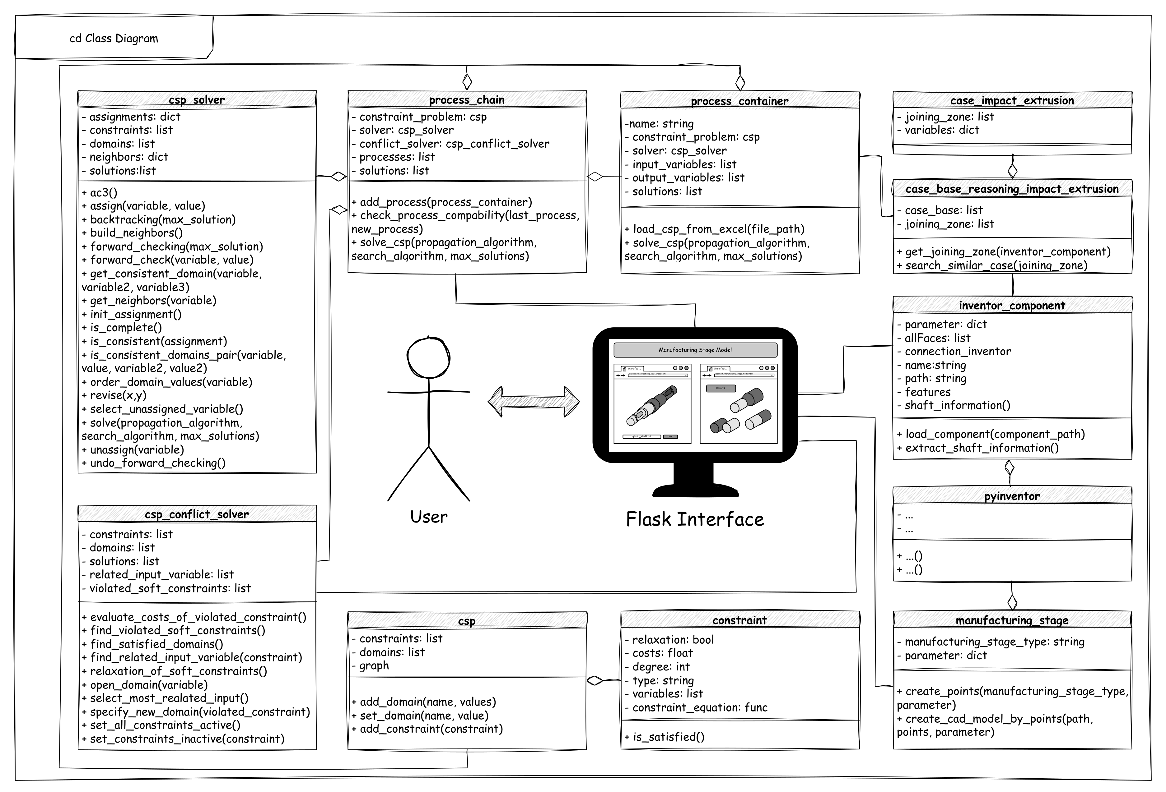
Figure 10, the implementation of the five modules is discussed. An object-oriented approach is pursued, since this makes a high modularity possible by independent program units, as well as the reuse of classes and functions as well as the inheritance of classes and thus the maintainability and expandability of the program facilitates. The conversion of the modules into responsible classes can be taken from the class diagram in
Figure 11. These are introduced in the following after the modules.
7.1. CAD Module
The CAD module consists of three classes. The first is a class that connects to Autodesk Inventor and has access to the open CAD documents within it. At this point we refer to the external library published on Github
pyinventor [
52] and the functionality is extended so that, among other things, the model parameters can be read in a structured way and the execution of model-internal iLogic rules from Python is possible. Based on this Inventor interface, the class
inventor_component follows. This can be used to open and examine component models. In order to be able to anticipate different approaches to model construction (e.g., dimensioning the half instead of the diameter in the 2D sketch), not only model parameters but also the Boundary-Representation (B-Rep) model are read out and related to each other. For rotationally symmetrical components, this means that length and diameter are determined paragraph by paragraph. In addition, the shape of the joining zone is determined and stored in the form of parameters according to Equation (
1). The class thus enables a structured representation of relevant component information, which in turn are the input parameters for the CSP.
manufacturing_stage is the last class in the CAD module. It contains design knowledge about the manufacturing stages and can generate CAD models for all manufacturing stages based on the configured parameters. Since the considered manufacturing stages are exclusively rotationally symmetric geometries, they can be represented in two dimensions by points connected to each other. These points can be positioned via parameters. To model the parts, the
manufacturing_stage creates a sketch within a new and empty Inventor part document and loads the points into the sketch. Then, the points are automatically connected to each other to form a closed profile and expanded to a three-dimensional body by a rotational extrusion. In the process, the manufacturing stages are initially created as a monomaterial component. This is dissolved by adding the joining zone, which depends on the manufacturing stage and different joining zone functions, e.g., a cone or Equation (
2). With these the joining zones can be modeled by discrete points and a connecting spline within a sketch. This sketch is then extruded to a surface. By means of a separation function, the created surface can be used as a tool to create the two bodies of a multimaterial component with a defined joining zone. Finally, a material assignment to the two individual bodies follows. Alternatively, manufacturing stages can also be created by previously created parametric geometry templates.
7.2. Process Chain Module
Within the Process Chain module, the process chain is formulated as a configuration problem by a CSPs. The class csp provides the basic possibility to model a CSP. For this purpose, this class has the following attributes: Domains, which contain the possible values for each variable as a dictionary, and a Constraints list, which contains all constraints as objects of a constraint class. A constraint object has, among other things, the attributes, variables involved, the constraint equation as a function, the degree of the constraint (e.g., unary, binary, higher order), the type of constraint (“hard” or “soft”), and the cost of suppressing the constraint when relaxing soft constraints. The function
is_satisfied() can be used within the constraint to check whether the constraint is satisfied given a value assignment. In addition, the csp class also has methods such as
add_domain() to add a new domain,
add_domain() to change a domain, and
add_constraint() to add a new constraint. The
add_constraint() method checks if all variables in a constraint are also present in the CSP, creates the constraint function, determines the degree of the constraint, and adds the constraint to the constraints list. Using the
create_graph function also create graph object to the constraint net, which contains the variables and constraints of the CSP as nodes and edges. For this purpose the library NetworkX [
53] is used. With the class csp general CSPs can now be formulated. Based on this, the process chain can be modeled by the classes
process_container and
process_chain.
The
process_container class represents a single process within the process chain and contains the
name,
csp,
input_variables, and
output_variables attributes. The variable csp is an instance of the csp class that contains the CSP formulation for this process. Furthermore, the variables
input_variables and
output_variables describe the names of the input and output variables of the process, respectively. The
load_csp_from_excel function transfers a user-friendly formulation of the variables and constraints of a process in Excel into a csp object. The
process_chain class describes the process chain as a whole and contains the processes and csp attributes, among others. The processes is a list of process containers containing the processes of the chain. The csp attribute is an instance of the csp class that contains the CSP formulation for the entire process chain. In addition, the
process_chain class contains two methods:
check_process_compability and
add_process. The
add_process method adds a new process to the process chain and transfers the domains and constraints of the process to the process chain. The
check_process_compability method also checks whether two successive processes are compatible with each other by comparing the
output_variables of an upstream process with the
input_variables of a downstream process. Besides, both the
process_container and
process_chain class have the
solve_CSP method, in which an object of
csp_solver class is created to solve the CSP. Due to the fact that the process containers can be solved independently of each other, it is later also possible to implement a distributed CSPs to get a better computational performance for complex problems [
54]. This structure of the process chains by process containers makes the dynamic configuration of Tailored Forming process chains possible, in which the static process chain default is dissolved by the user by a process chain with suitable heuristics on the basis of which the examined construction unit is derived and automated. In addition, different process chain variants can also be examined and evaluated against each other.
7.3. Case-Based Reasoning Module
For the implementation of case-based reasoning, this module has two classes together:
case_bases_reasoning_impact_extrusion and
case_impact_extrusion. The class
case_bases_reasoning_impact_extrusion formalizes individual cases of simulated impact extrusion processes via the attributes
joining_zone, which describes the simulated joining zone, and
variables, which includes the parameters that led to this joining zone. These cases are then combined into a case base class. Based on this, the class can read a joining zone from a
inventor_component using the
get_joining_zone() method and find similar simulated joining zones using the
search_simular_case() method. In doing so, the method iterates over each entry in the case base and calculates the Hamming distance (Equation (
2)). Then, the case with the highest Hamming distance (the highest match) is selected and its variable assignment from input variables is passed to the process container
impact_extrusion as a domain constraint.
7.4. CSP Solver Module
The CSP solver is modeled using the
csp_solver class, where different algorithms for constraint propagation and solution search can be implemented. By establishing a connection to the CSP object, it is possible to solve the formalized CSP using the implemented algorithms. A combined solution strategy is used, which first constrains the domains by applying constraint propagation to ensure edge consistency. Here, the AC-3 algorithm is used to check the consistency of the binary constraints [
43,
44,
45]. However, higher order constraints are not considered in this strategy. Since no unary constraints are provided by the presented constraint modeling strategy (see
Section 4), an examination of node consistency was not performed. After the domains have been constrained, a concrete solution search is performed using a backtracking algorithm that is implemented recursively. Alternatively, a forward checking algorithm is available for the solution search, which has a higher performance. With this implementation of the CSP solver it is also possible to realize parallel solution processes by creating multiple solver objects.
7.5. CSP Conflict Solver Module
The Conflict Solver is used to resolve arising conflicts during the solving of the CSP either on the resource or on the component side and is implemented as a separate class. Within these classes, several methods are available. The
find_violated_soft_constraints method is used to identify constraints that cause a conflict in the constraint network. For this purpose, all combinations of soft constraints are started as a solution process in which the selected soft constraint combination is not considered in the solution search. Individual
csp_solver objects are created in each case for the solution search. Since these solving processes of the combinations run independently, the computation time is reduced by running the solving processes in parallel (multi-threading). If a solution is found when a combination is suppressed, the combination triggers a conflict. These combinations are then stored in a list. Once the conflicts have been identified, the user is asked whether they should be resolved on the resource side or on the component side. In the case of component-side resolution, all input variables that are directly related to the conflicting constraints are searched for first. For this purpose, a path search with the Dijkstra algorithm is performed within the CSP graph. The Dijkstra algorithm is available within the implemented library
NetworkX [
53]. If an optional domain is assigned to the identified input variables, it is taken over. If this is not the case, the domain is directly expanded to a quasi-continuous range of integer numbers.
For the resource-side resolution, the resource-related variables are identified within the conflicting constraints. Since the constraints follow a fixed scheme, these are found on the right-hand side of the equation. Subsequently, the opening of these variables also follows a quasi-continuous range of integer numbers. The resulting configuration problem thus also includes the specification of the required manufacturing resources of the CSP modified by the component-sided or resource-sided solution. Again a solution process is started via a csp_solver object. The resulting solutions then represent possible alternative solutions that enable the production of the examined component. If several alternative solutions are to occur, these can be evaluated finally over the resulting costs. For this purpose, the costs are added to each solution by adding the costs of the constraints that were previously suppressed in the process.
All classes are merged into a separate
main script, which coordinates the processes according to
Figure 10 of the manufacturing stage model. This also involves the integration of the Graphical User Interface in Flask. Overall, this system architecture provides a useful implementation for solving CSP problems as it is modular and easy to use through the use of classes and methods and can be adaptively applied to other problems as well.
8. Discussion
The presented assistance system was validated on a tailored forming process chain for manufacturing a multimaterial shaft. The simplification was made that macroscopic and microscopic material effects during manufacturing, such as microstructural changes or stress states, were largely neglected and, for example, only represented in the external surrogate model of extrusion by material temperatures and equivalent stresses. Furthermore, manufacturing uncertainties due to tolerances have not yet been taken into account. However, this is planned as a future extension. Currently, the presented approach is applied to two alternative manufacturing process chains for the production of multi-material shafts.
Regarding the modeling and exploration strategy, the presented approach offers both advantages and disadvantages. The formalization of the process chain by a CSP requires the abstraction of manufacturing processes into finite domains. Increasing the degrees of freedom by expanding the domains is possible, but it has an exponential impact on computer capacity and runtime as the possible solution space is increased. In order to increase the resolution of manufacturing processes in the future by quasi-continuous domains, a specific solver is currently being developed, which removes invalid domain values via boundary value determination by constraint propagation in advance and thus increases the efficiency in the solution search—especially for large solution spaces. In contrast to empirical methods for process modeling, as in Ref. [
34], a pre-thinking of the solution space is required. This must be described in advance by explicit constraints. Thus, a deep understanding of the cause–effect relationships within manufacturing processes is required during modeling in order to build a basic constraint framework for a process container. At the same time, it must be decided whether external surrogate models are necessary in addition to the process constraints in order to obtain a sufficient depth of description. With respect to constraint modeling, the presented constraints solver has the advantage that it is able to consider more complicated numerical expressions, such as
or
, for constraint modeling in addition to the common Boolean operators, compared to other constraint-based methods such as Ref. [
39], whose reasoning is mapped rule-based using the Semantic Web Rule Language. Overall, frontloading the solution space has the disadvantage that the model is limited in degrees of freedom. In return, the solution process is robust due to a clear predefined solution search strategy via the constraint solver. If more flexibility is required or if large complex constraint problems exist, distributed approaches in the form of a multi-agent system, as in Ref. [
41] are a possibility to deal with this. In this way, the complex problems can be solved in a stepwise and decentralized manner by autonomously interacting agents. An interaction between the agents finally leads to a collaborative solution. Here, distributed constraint satisfaction problems [
54] provide a basis to further extend the presented approach in future research.
The architecture of the assistance system is designed to be easy to maintain, extend, and update. Thus, the defined initial domains can be adapted to learn iteratively from previously conducted investigations and to narrow down the solution spaces in advance. The generic implementation also provides a basis for further developing the model into a kernel in order to achieve transferability to other process chains with a reduced implementation effort. This is of particular interest when a high simulation effort is required to validate component designs with respect to manufacturability within multi-stage process chains.
9. Conclusions and Outlook
This article presents an assistance system for decision support in the context of design for manufacturing. The assistance system possesses explicit manufacturing process chain knowledge and has an inference engine that automatically evaluates the manufacturability of a component design based on a given manufacturing process chain and can resolve emerging manufacturing conflicts through component-side or resource-side adjustments. A link with a CAD system additionally enables the three-dimensional representation of derived manufacturing stages and manufacturing resources. Within the assistance system, a manufacturing process chain is understood as a configurable design object and modeled via discrete domains. Together, applicable process contexts and existing manufacturing constraints, which can be formulated as constraints, result in a configuration problem that can be implemented via a CSP. Furthermore, external surrogate models can be integrated to the constraint and domain knowledge to represent a more precise description of manufacturing processes.
In future research, the assistance system will be enhanced to be able to configure entire process chains. Thus, the premise of a given process chain will be dissolved and the assistance system will be able to initialize the CSP automatically by the process containers, to perform a canting of the variables, and to generate the configuration problem in a component-specific manner. This will also enable the investigation and evaluation of different process chain variants. A challenge here is that a process chain configuration is both a planning and sequencing problem. This requires the development of a new process chain called the configurator.
In summary, the presented assistance system represents an added value in that valuable manufacturing information for component designs can be automatically accessed and made available in an explicit form already during component development.
Author Contributions
Conceptualization, K.H., S.P. and P.C.G.; Methodology, P.C.G.; Software, K.H.; Formal analysis, P.C.G.; Investigation, K.H.; Resources, S.P.; Data curation, S.P. and P.C.G.; Writing—original draft, K.H. and P.C.G.; Writing—review and editing, S.P. and P.C.G.; Visualization, K.H.; Supervision, P.C.G. and R.L.; Project administration, P.C.G. and R.L.; Funding acquisition, R.L. All authors contributed equally to the article. All authors have read and agreed to the published version of the manuscript.
Funding
The results of this publication have been developed within the framework of the Collaborative Research Center 1153 “Process Chain for the Manufacture of Hybrid High-Performance Components by Tailored Forming” within the subproject C02. The authors would like to thank the German Research Foundation (DFG) for financial and organizational support of the project (project number: 252662854). In addition the publication of this article was funded by the Open Access Fund of Leibniz Universität Hannover.
Data Availability Statement
All data were presented in the main text.
Conflicts of Interest
The authors declare no conflict of interest.
References
- Ehrlenspiel, K.; Kiewert, A.; Lindemann, U.; Mörtl, M. Kostengünstig Entwickeln und Konstruieren, 8th ed.; Springer: Berlin/Heidelberg, Germany, 2020. [Google Scholar] [CrossRef]
- Ozbayrak, M.; Akgün, M.; Türker, A. Activity-based cost estimation in a push/pull advanced manufacturing system. Int. J. Prod. Econ. 2004, 87, 49–65. [Google Scholar] [CrossRef]
- Bender, B.; Gericke, K. Pahl/Beitz Konstruktionslehre; Springer: Berlin/Heidelberg, Germany, 2021. [Google Scholar] [CrossRef]
- Liao, K.; Ma, Z.; Lee, J.J.Y.; Ke, K. Achieving mass customization through trust-driven information sharing: A supplier’s perspective. Manag. Res. Rev. 2011, 34, 541–552. [Google Scholar] [CrossRef]
- Pitiot, P.; Aldanondo, M.; Vareilles, E. Concurrent product configuration and process planning: Some optimization experimental results. Comput. Ind. 2014, 65, 610–621. [Google Scholar] [CrossRef]
- Ferguson, S.M.; Olewnik, A.T.; Cormier, P. A review of mass customization across marketing, engineering and distribution domains toward development of a process framework. Res. Eng. Des. 2014, 25, 11–30. [Google Scholar] [CrossRef]
- Aldanondo, M.; Vareilles, E. Configuration for mass customization: How to extend product configuration towards requirements and process configuration. J. Intell. Manuf. 2008, 19, 521–535. [Google Scholar] [CrossRef]
- Anjum, N.; Harding, J.A.; Young, R.I.; Case, K. Manufacturability verification through feature-based ontological product models. Proc. Inst. Mech. Eng. Part B J. Eng. Manuf. 2012, 226, 1086–1098. [Google Scholar] [CrossRef]
- Herrmann, K.; Brockmöller, T.; Gembarski, P.; Mozgova, I.; Lachmayer, R. Manufacturing stage-based design model for mechanical components. In Proceedings of the Stuttgarter Symposium für Produktentwicklung SSP 2021, Stuttgart, Germany, 20 May 2021; pp. 247–258. [Google Scholar] [CrossRef]
- Behrens, B.A.; Goldstein, R.; Guisbert, D.; Duran, D. Thermomechanical Processing of Friction Welded Steel-Aluminum Billets to Improve Joining Zone Properties. In Proceedings of the IFHTSE TPIM Conference, Spartanburg, SC, USA, 5–7 June 2018. [Google Scholar]
- Herrmann, K.; Pusch, F.; Plappert, S.; Bode, B.; Mozgova, I.; Gembarski, P.C.; Lachmayer, R. Prozesskettenorientierte Herstellbarkeitsanalyse von Produkten durch die Nutzung eines Constraint-Satisfaction-Problems. In Proceedings of the Stuttgarter Symposium für Produktentwicklung SSP 2023, Stuttgart, Germany, 25 May 2023. [Google Scholar]
- Suh, N.P. Complexity: Theory and Applications; Oxford University Press: Oxford, UK, 2005. [Google Scholar]
- Fredendall, L.D.; Gabriel, T.J. Manufacturing complexity: A quantitative measure. In Proceedings of the POMS Conference, Savannah, GA, USA, 4–7 April 2003. [Google Scholar]
- Gembarski, P.C. Modeling the Portfolio of Capabilities for Product Variant Creation and Assessment. In Proceedings of the 9th International Conference on Mass Customizaon and Personalizaon—Community of Europe (MCP-CE 2020), Novi Sad, Serbia, 23–25 September 2020. [Google Scholar]
- Ashby, M.; Cebon, D. Materials selection in mechanical design. J. Phys. IV 1993, 3, C7-1–C7-9. [Google Scholar] [CrossRef]
- Behrens, B.A.; Bonhage, M.; Bohr, D.; Duran, D. Simulation Assisted Process Development for Tailored Forming. Mater. Sci. Forum 2019, 949, 101–111. [Google Scholar] [CrossRef]
- Fritz, A.H. Fertigungstechnik, 11th ed.; Springer: Berlin/Heidelberg, Germany, 2015. [Google Scholar] [CrossRef]
- Brockmöller, T.; Siqueira, R.; Gembarski, P.C.; Mozgova, I.; Lachmayer, R. Computer-Aided Engineering Environment for Designing Tailored Forming Components. Metals 2020, 10, 1589. [Google Scholar] [CrossRef]
- Denkena, B.; Bergmann, B.; Breidenstein, B.; Prasanthan, V.; Witt, M. Analysis of potentials to improve the machining of hybrid workpieces. Prod. Eng. 2019, 13, 11–19. [Google Scholar] [CrossRef]
- Behrens, B.A.; Uhe, J. Introduction to tailored forming. Prod. Eng. 2021, 15, 133–136. [Google Scholar] [CrossRef]
- Ullman, D.G. The Mechanical Design Process; David Ullman LLC: Independence, OR, USA, 2009. [Google Scholar]
- Tempelman, E.; Van Eyben, B.N.; Shercliff, H. Manufacturing and Design: Understanding the Principles of How Things Are Made; Butterworth-Heinemann: Oxford, UK, 2014; pp. 1–297. [Google Scholar] [CrossRef]
- Gembarski, P.C.; Sauthoff, B.; Brockmöller, T.; Lachmayer, R. Operationalization of Manufacturing Restrictions for CAD and KBE-Systems. In Proceedings of the DESIGN 2016 14th International Design Conference, Dubrovnik, Croatia, 16–19 May 2016; pp. 621–630. [Google Scholar]
- Babic, B. Axiomatic design of flexible manufacturing systems. Int. J. Prod. Res. 2010, 37, 1159–1173. [Google Scholar] [CrossRef]
- Suh, N.P. Axiomatic Design Theory for Systems. Res. Eng. Des. Theory, Appl. Concurr. Eng. 1998, 10, 189–209. [Google Scholar] [CrossRef]
- Gonçalves-Coelho, A.M.; Mourão, A.J. Axiomatic design as support for decision-making in a design for manufacturing context: A case study. Int. J. Prod. Econ. 2007, 109, 81–89. [Google Scholar] [CrossRef]
- Doellken, M.; Zimmerer, C.; Matthiesen, S. Challenges Faced by Design Engineers when Considering Manufacturing in Design—An Interview Study. Proc. Des. Soc. Des. Conf. 2020, 1, 837–846. [Google Scholar] [CrossRef]
- Groche, P.; Bruder, E.; Gramlich, S. Manufacturing Integrated Design; Springer International Publishing: Cham, Switzerland, 2017. [Google Scholar] [CrossRef]
- Vajna, S.; Weber, C.; Zeman, K.; Hehenberger, P.; Gerhard, D.; Wartzack, S. CAx für Ingenieure; Springer: Berlin/Heidelberg, Germany, 2018. [Google Scholar] [CrossRef]
- Mönch, L.; Stehli, M. ManufAg: A multi-agent-system framework for production control of complex manufacturing systems. Inf. Syst. Bus. Manag. 2006, 4, 159–185. [Google Scholar] [CrossRef]
- Sun, J.; Zhang, Y.F.; Nee, A.Y.C. A distributed multi-agent environment for product design and manufacturing planning. Int. J. Prod. Res. 2001, 39, 625–645. [Google Scholar] [CrossRef]
- Martin, P. Some Aspects of Integrated Product and Manufacturing Process. In Advances in Integrated Design and Manufacturing in Mechanical Engineering; Springer: Dordrecht, The Netherlands, 2005; pp. 215–226. [Google Scholar] [CrossRef]
- Rippel, D.; Lütjen, M.; Freitag, M. Geometrieorientierter Prozesskettenentwurf für die Mikrofertigung. Ind. Manag. 2016, 32, 50–53. [Google Scholar]
- Kulkarni, N.; Gupta, R.; Khan, D.; Gautham, B.P.; Allen, J.K.; Panchal, J.; Mistree, F. Inverse Design of Manufacturing Process Chains; American Society of Mechanical Engineers: New York, NY, USA, 2014. [Google Scholar] [CrossRef]
- Lee, C.H.; Lee, D.H.; Bae, Y.M.; Choi, S.H.; Kim, K.H.; Kim, K.J. Approach to derive golden paths based on machine sequence patterns in multistage manufacturing process. J. Intell. Manuf. 2022, 33, 167–183. [Google Scholar] [CrossRef]
- Milisavljevic-Syed, J.; Commuri, S.; Allen, J.K.; Mistree, F. A method for the concurrent design and analysis of networked manufacturing systems. Eng. Optim. 2019, 51, 699–717. [Google Scholar] [CrossRef]
- Nellippallil, A.B.; Rangaraj, V.; Gautham, B.P.; Singh, A.K.; Allen, J.K.; Mistree, F. An Inverse, Decision-Based Design Method for Integrated Design Exploration of Materials, Products, and Manufacturing Processes. J. Mech. Des. 2018, 140, 111403. [Google Scholar] [CrossRef]
- Albrecht, K.; Anderl, R. Information Model for the Integration of Manufacturing Restrictions into the Algorithm Based Product Development Process. Procedia CIRP 2016, 50, 819–824. [Google Scholar] [CrossRef]
- Li, Z.; Zhou, X.; Wang, W.M.; Huang, G.; Tian, Z.; Huang, S. An ontology-based product design framework for manufacturability verification and knowledge reuse. Int. J. Adv. Manuf. Technol. 2018, 99, 2121–2135. [Google Scholar] [CrossRef]
- Nguyen, V.D.; Martin, P. Product design-process selection-process planning integration based on modeling and simulation. Int. J. Adv. Manuf. Technol. 2015, 77, 187–201. [Google Scholar] [CrossRef]
- Plappert, S.; Becker, C.; Gembarski, P.C.; Lachmayer, R. Feasibility Evaluation of Milling Designs Using Multi-Agent Systems. Proc. Des. Soc. 2022, 2, 763–772. [Google Scholar] [CrossRef]
- Herrmann, K.; Altun, O.; Wolniak, P.; Mozgova, I.; Lachmayer, R. Methodical design of development environments according to the Generative Parametric Design Approach. In Proceedings of the 32nd Symposium Design for X, DFX 2021, Tutzing, Germany, 27–28 September 2021. [Google Scholar] [CrossRef]
- Brailsford, S.C.; Potts, C.N.; Smith, B.M. Constraint satisfaction problems: Algorithms and applications. Eur. J. Oper. Res. 1999, 119, 557–581. [Google Scholar] [CrossRef]
- Kumar, V. Algorithms for Constraint-Satisfaction Problems: A Survey. AI Mag. 1992, 13, 32. [Google Scholar] [CrossRef]
- Bartak, R. Constraint Propagation and Backtracking-Based Search; Charles Universität: Prague, Czech Republic, 2005. [Google Scholar]
- Felfernig, A.; Hotz, L.; Bagley, C.; Tiihonen, J. Knowledge-Based Configuration; Elsevier: Amsterdam, The Netherlands, 2014. [Google Scholar] [CrossRef]
- Stokes, M. Managing Engineering Knowledge: MOKA-Methodology for Knowledge Based Engineering Applications; Wiley-Blackwell: Hoboken, NJ, USA, 2001. [Google Scholar]
- Behrens, B.A.; Duran, D.; Matthias, T.; Ross, I. Enhancement of the interface of friction welded steel-aluminium joints. Prod. Eng. 2021, 15, 169–176. [Google Scholar] [CrossRef]
- Siqueira, R.; Bibani, M.; Mozgova, I.; Lachmayer, R. Case-based parametric analysis: A method for design of tailored forming hybrid material component. Adv. Intell. Syst. Comput. 2019, 853, 14–28. [Google Scholar] [CrossRef]
- Freudenthaler, B. Case-Based Reasoning (CBR): Grundlagen und Ausgewählte Anwendungsgebiete des Fallbasierten Schließens; AV Akademikerverlag: Saarbrücken, Germany, 2012. [Google Scholar]
- Ronacher, A. Flask. GitHub Repos. 2023. Available online: https://github.com/pallets/flask (accessed on 5 January 2023).
- Oriani, A. PyInventor—A Python based Autodesk Inventor API module. GitHub Repos. 2021. Available online: https://github.com/AndrewOriani/PyInventor (accessed on 10 December 2022).
- Hagberg, A.A.; Schult, D.A.; Swart, P.J. Exploring Network Structure, Dynamics, and Function using NetworkX. In Proceedings of the 7th Python in Science Conference, Pasadena, CA, USA, 19–24 August 2008; Varoquaux, G., Vaught, T., Millman, J., Eds.; Lulu Press Inc.: Morrisville, NC, USA, 2008; pp. 11–15. [Google Scholar]
- Yokoo, M.; Durfee, E.H.; Ishida, T.; Kuwabara, K. The Distributed Constraint Satisfaction Problem: Formalization and Algorithms. IEEE Trans. Knowl. Data Eng. 1998, 10, 673–685. [Google Scholar] [CrossRef]
| Disclaimer/Publisher’s Note: The statements, opinions and data contained in all publications are solely those of the individual author(s) and contributor(s) and not of MDPI and/or the editor(s). MDPI and/or the editor(s) disclaim responsibility for any injury to people or property resulting from any ideas, methods, instructions or products referred to in the content. |
© 2023 by the authors. Licensee MDPI, Basel, Switzerland. This article is an open access article distributed under the terms and conditions of the Creative Commons Attribution (CC BY) license (https://creativecommons.org/licenses/by/4.0/).


