
Irregular Workpiece Template-Matching Algorithm Using Contour Phase


Abstract
:1. Introduction
2. Template Matching Based on Geometric Features and Hu Invariant Moments
2.1. Construction of the Base Feature Vector
2.2. Create Template Base Feature Vectors
3. Algorithm Principle
3.1. Scheme Description
3.2. Method of Calculating the Center of Mass Based on Hu Invariant Moments
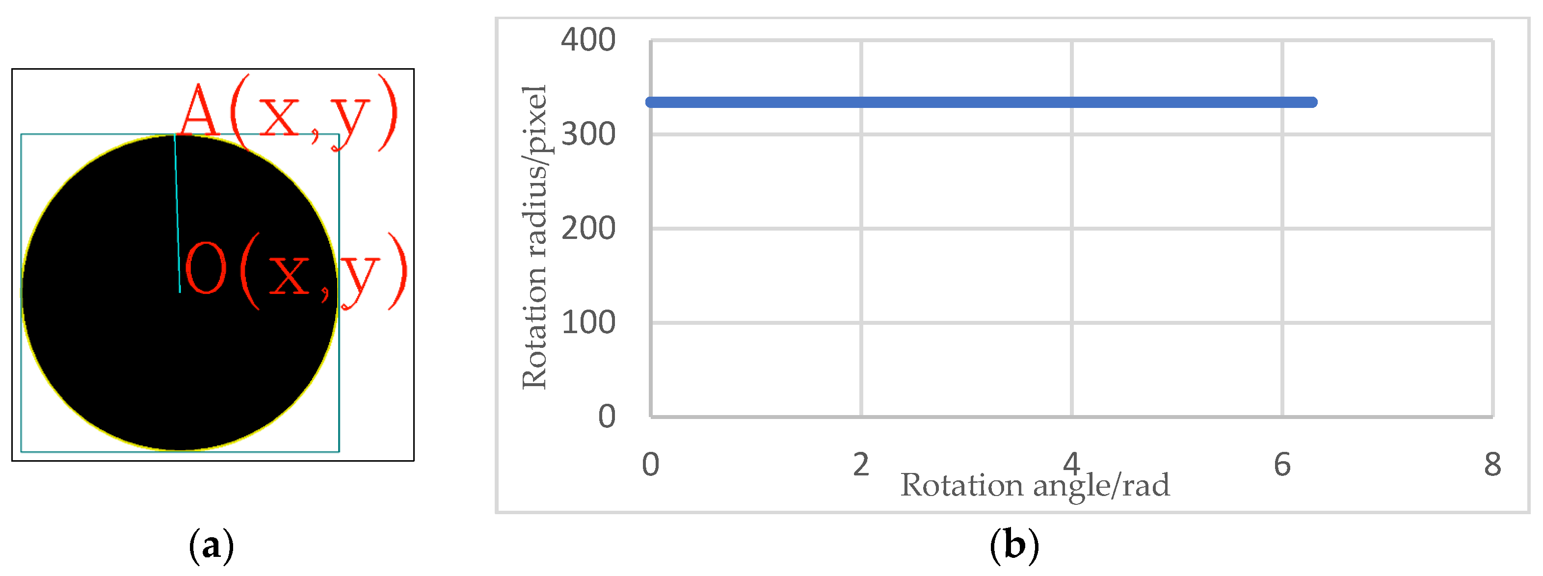
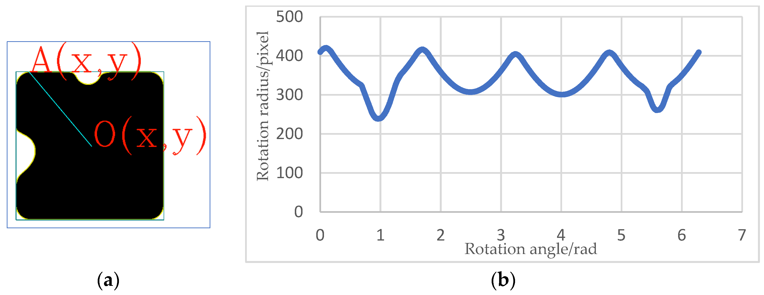
3.3. Contour Feature Vector Computing Based on Rotating Radius Cluster
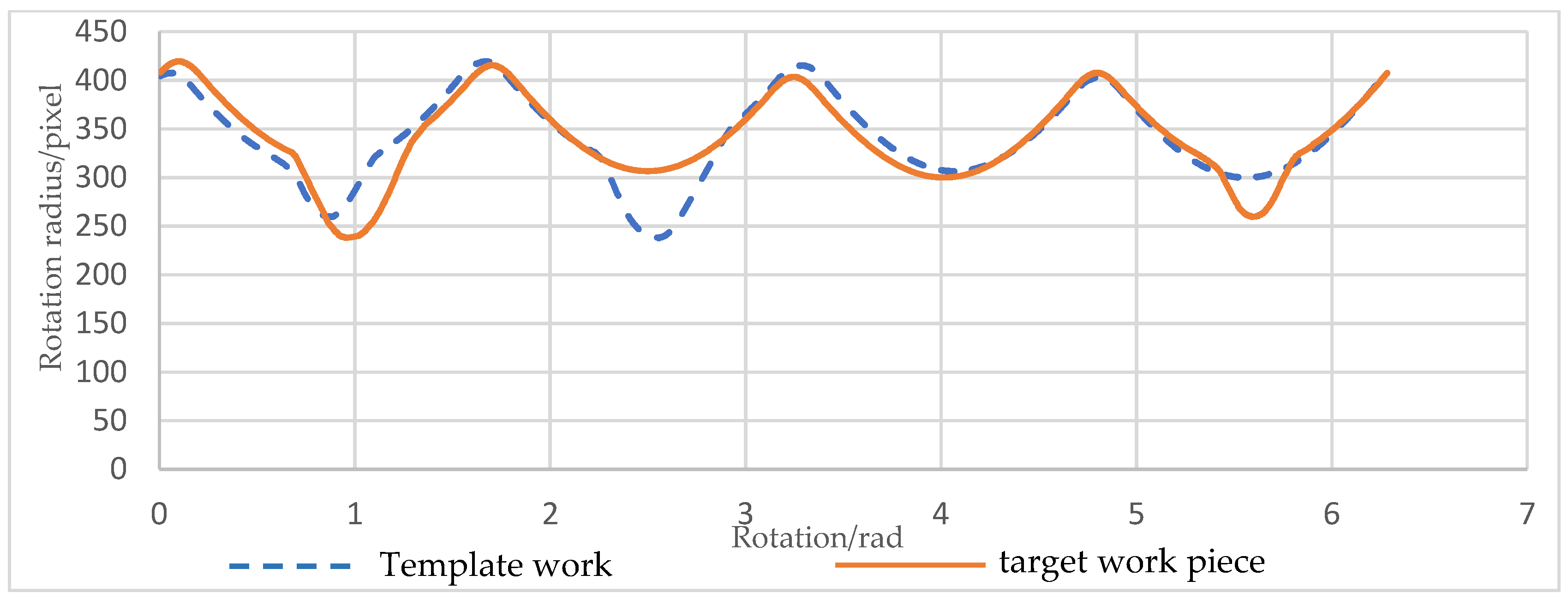
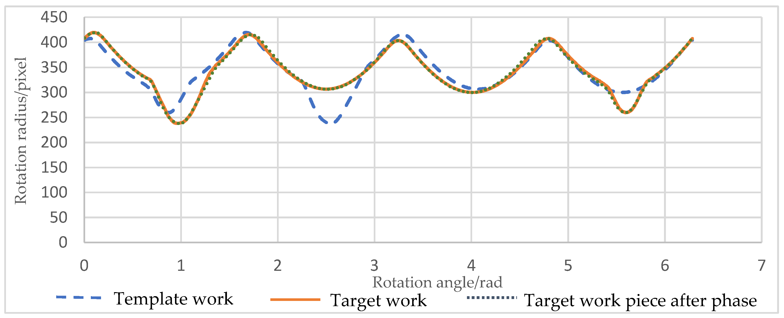
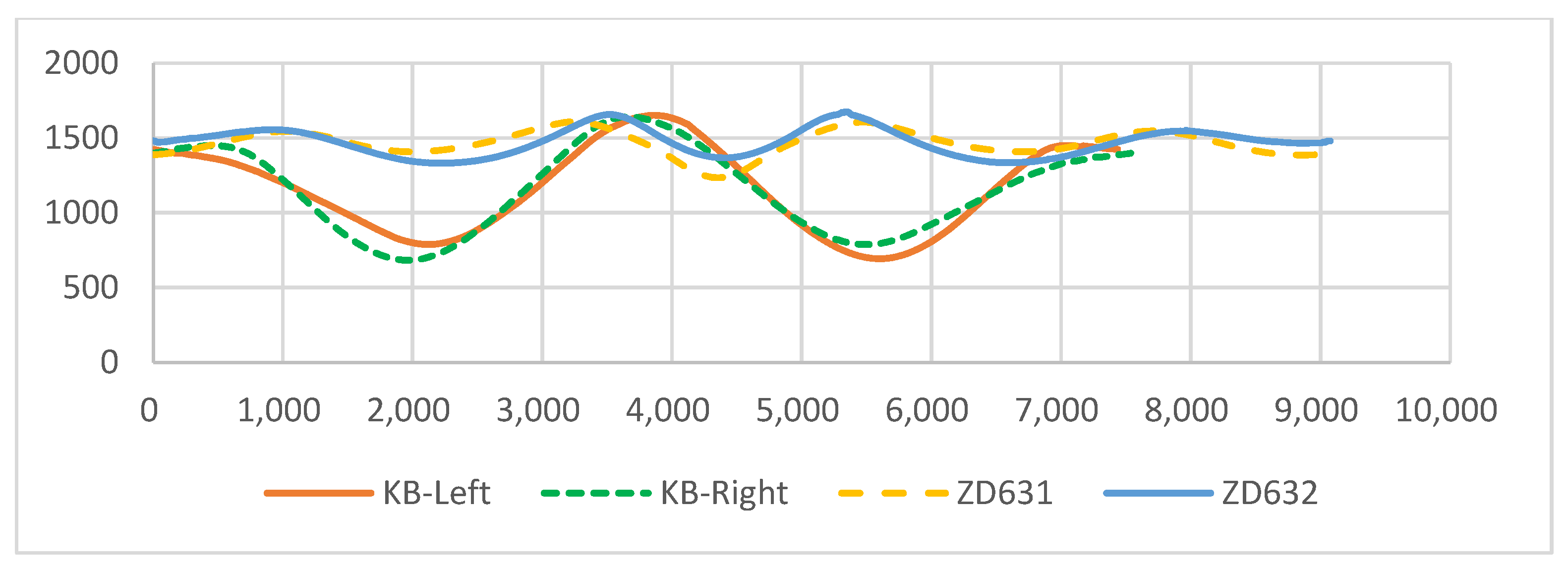
- Phase difference matching calculation
- Rotation angle calculation
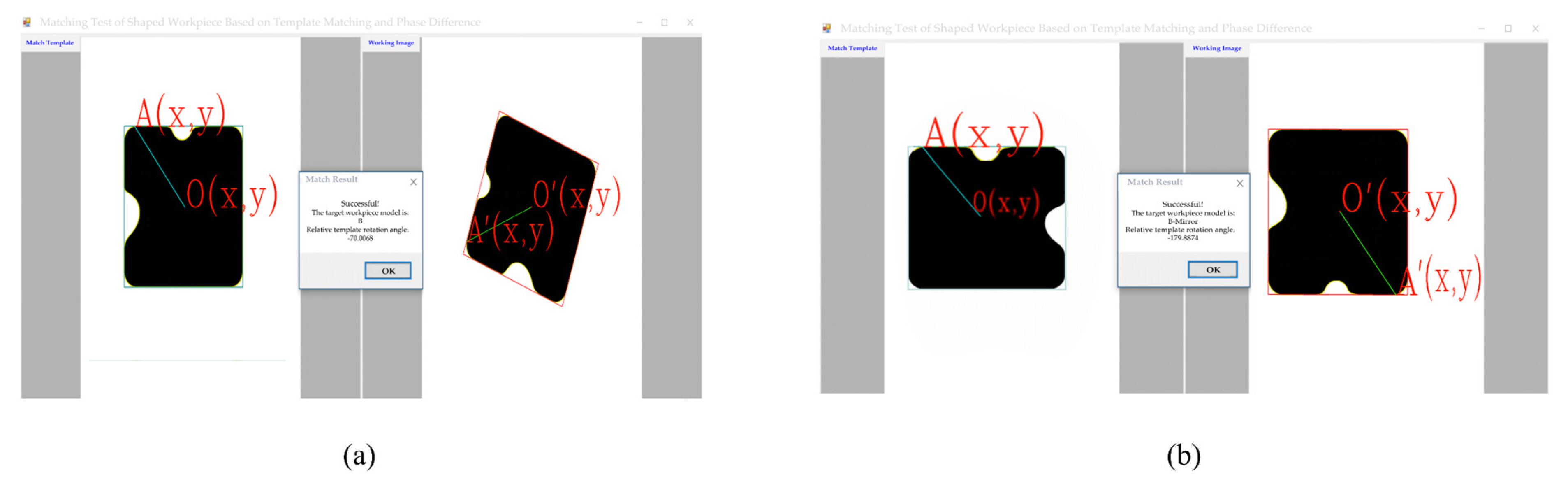
4. Experimental Analysis and Verification
5. Conclusions
Author Contributions
Funding
Institutional Review Board Statement
Informed Consent Statement
Data Availability Statement
Conflicts of Interest
References
- Benfriha, K.; El-Zant, C.; Charrier, Q.; Bouzid, A.-H.; Wardle, P.; Belaidi, I.; Loubère, S.; Ghodsian, N.; Aoussat, A. Development of an advanced MES for the simulation and optimization of industry 4.0 process. Int. J. Simul. Multidiscip. Des. Optim. 2021, 12, 23. [Google Scholar] [CrossRef]
- Won, D.J.; Moon, J.H. Advanced template matching prediction using a motion boundary. In Proceedings of the the 2nd International Conference on Image and Graphics Processing(ICIGP), Singapore, 23–25 February 2019; pp. 110–113. [Google Scholar] [CrossRef]
- Zhu, M.; Chen, C.; Sun, D. Improved Template Matching Algorithm Based on Feature Point Matching. Comput. Digit. Eng. 2022, 50, 377–382. [Google Scholar]
- Ma, H. Research on Automatic Focusing and Mosaic Algorithms of Pathological Microscopic Images; North University of China: Taiyuan, China, 2019. [Google Scholar]
- Wu, X.; Zou, G. High performance template matching algorithm based on edge geometric features. Chin. J. Entific Instrum. 2013, 34, 1462–1469. [Google Scholar] [CrossRef]
- Rao, T. Video Image Processing Method And Apparatus Thereof, Display Device, Computer Readable Storage Medium And Computer Program Product (USPTO 20200134793). 2020. Available online: https://www.freepatentsonline.com/y2020/0134793.html (accessed on 10 June 2022).
- Jin, S.; Li, X.; Yang, X.; Zhang, J.A.; Shen, D. Identification of Tropical Cyclone Centers in SAR Imagery Based on Template Matching and Particle Swarm Optimization Algorithms. IEEE Trans. Geosci. Remote Sens. 2018, 57, 598–608. [Google Scholar] [CrossRef]
- Lu, Y.; Zhang, X.; Pang, S.; Li, H.; Zhu, B. A robust edge-based template matching algorithm for displacement measurement of compliant mechanisms under scanning electron microscope. Rev. Sci. Instrum. 2021, 92, 033703. [Google Scholar] [CrossRef]
- Cui, Z.; Qi, W.; Liu, Y. A Fast Image Template Matching Algorithm Based on Normalized Cross Correlation. J. Phys. Conf. Ser. 2020, 1693, 012163. [Google Scholar] [CrossRef]
- Yang, Y.A.; Zhuo, C.A.; Xl, B.; Wg, C.; Dz, D.; Mx, E. Robust template matching with large angle localization. Neurocomputing 2020, 398, 495–504. [Google Scholar] [CrossRef]
- Tsai, C.Y.; Yu, C.C. Real-time Textureless Object Detection and Recognition Based on an Edge-based Hierarchical Template Matching Algorithm. J. Appl. Sci. Eng. 2018, 21, 229–240. [Google Scholar] [CrossRef]
- He, Z.; Jiang, Z.; Zhao, X.; Zhang, S.; Wu, C. Sparse Template-Based 6-D Pose Estimation of Metal Parts Using a Monocular Camera. IEEE Trans. Ind. Electron. 2020, 67, 390–401. [Google Scholar] [CrossRef]
- Han, Y. Reliable Template Matching for Image Detection in Vision Sensor Systems. Sensors 2021, 21, 8176. [Google Scholar] [CrossRef]
- Gharavi-Alkhansari, M. A fast globally optimal algorithm for template matching using low-resolution pruning. IEEE Trans. Image Process. 2001, 10, 526–533. [Google Scholar] [CrossRef] [PubMed]
- Zheng, J.; Zheng, L.; Zhu, J. A Fast Template Matching Method Based on Gray Level. Mod. Comput. 2018, 26, 52–56. [Google Scholar]
- Hsu, C.T.; Shih, M.C. Content-based image retrieval by interest-point matching and geometric hashing. In Proceedings of the SPIE—The International Society for Optical Engineering, Shanghai, China, 15–17 October 2002; pp. 80–90. [Google Scholar] [CrossRef]
- Zhan, H. Design and Implementation of Image Recognition Algorithm Based on Improved Moment Invariants and Principal Component Analysis. J. Jilin Inst. Chem. Technol. 2017, 34, 27–30. [Google Scholar] [CrossRef]
- Zhou, L. Research and Application of Vision Positioning Technology Based on Template Matching; Dalian University of Technology: Dalian, China, 2012. [Google Scholar]
- Yang, H.; Zhang, G. Design and realization of a new correlation tracker algorithm. J. Infrared Millim. Waves 2000, 5, 377–380. [Google Scholar]
- Zhang, K.; Hu, B.; Xu, X.; Li, X. A fast correlation matching algorithm based on log-polar transform. Flight Dyn. 2020, 38, 61–65. [Google Scholar] [CrossRef]
- Jiang, S.; Li, C.; Yang, R.; Zhou, X. Regular planar geometric workpiece sorting method based on machine vision. Ind. Control Comput. 2015, 28, 102–104. [Google Scholar]
- Mei, Y.; Xiong, C.; Fan, S. Design and implementation of an intelligent sorting system for parts of 3C products. Mod. Manuf. Technol. Equip. 2018, 10, 16–17,20. [Google Scholar] [CrossRef]
- Li, B.; Tan, F.; Han, Y. Method for recognizing and positionig ceramic substrate. Ind. Control Comput. 2019, 32, 95–97. [Google Scholar]
- Zhang, L.; Wu, X. An edge-guided image interpolation algorithm via directional filtering and data fusion. IEEE Trans. Image Process. 2006, 15, 2226–2238. [Google Scholar] [CrossRef]
- Sun, C.; Pan, Q.; Liu, Z.; Wang, J. Automatic recognition and location system for electric vehicle charging port in complex environment. IET Image Process. 2020, 14, 2263–2272. [Google Scholar] [CrossRef]
- Quan, P.; Lou, Y.n.; Lin, H.; Liang, Z.; Wei, D.; Di, S. Research on Fast Recognition and Localization of an Electric Vehicle Charging Port Based on a Cluster Template Matching Algorithm. Sensors 2022, 22, 3599. [Google Scholar] [CrossRef] [PubMed]
- Li, L.; Lv, Z.; Chen, X.; Qiu, Y.; Li, L.; Ma, A.; Zheng, S.; Chai, X. Research on track fastener positioning method based on local unidirectional template matching. Sci. Prog. 2021, 104, 1–15. [Google Scholar] [CrossRef] [PubMed]
- Wu, G.; Yu, M.; Shi, W.; Li, S.; Bao, J. Image recognition in online monitoring of power equipment. Int. J. Adv. Robot. Syst. 2020, 17, 1729881419900836. [Google Scholar] [CrossRef]
- Cai, J.; Lei, T. An Autonomous Positioning Method of Tube-to-Tubesheet Welding Robot Based on Coordinate Transformation and Template Matching. IEEE Robot. Autom. Lett. 2021, 6, 787–794. [Google Scholar] [CrossRef]
- Huang, J.; Cai, X.; Yu, N. Orientation codes-based image template matching method on workpiece inspection. Electron. Des. Eng. 2011, 19, 128–130,133. [Google Scholar] [CrossRef]
- Hu, M.K. Visual Pattern Recognition by Moment Invariants. Inf. Theory IRE Trans. 1962, 8, 179–187. [Google Scholar] [CrossRef]
- Chen, C.C. Improved moment invariants for shape discrimination. Proc. SPIE Int. Soc. Opt. Eng. 1993, 26, 683–686. [Google Scholar] [CrossRef]


| Category | M1 | M2 | Area | Circumference | Ratio of Long to Short Radius | Radius Mean | Radius Variance |
|---|---|---|---|---|---|---|---|
| A | 0.30242455 | 0.00825412 | 125,959 | 2292 | 4.429 | 232.49 | 87.62 |
| B | 0.17034508 | 0.00001640 | 362,931 | 2368 | 1.763 | 341.89 | 44.11 |
| B-Mirror | 0.17034508 | 0.00001640 | 362,931 | 2368 | 1.763 | 341.89 | 44.11 |
| C | 0.18838271 | 0.00157881 | 248,166 | 1983 | 2.684 | 290.29 | 62.25 |
| D | 0.25531456 | 0.03709374 | 212,668 | 1902 | 3.585 | 278.40 | 94.46 |
| D-Mirror | 0.25531456 | 0.03709374 | 212,668 | 1902 | 3.585 | 278.40 | 94.46 |
| Target Work Piece | Rotation Angle (Degree) | Template | The Proposed Algorithm (Degree) | Error | Calculation Angle of Exterior Rectangle [21,22,23] (Degree) | Error |
|---|---|---|---|---|---|---|
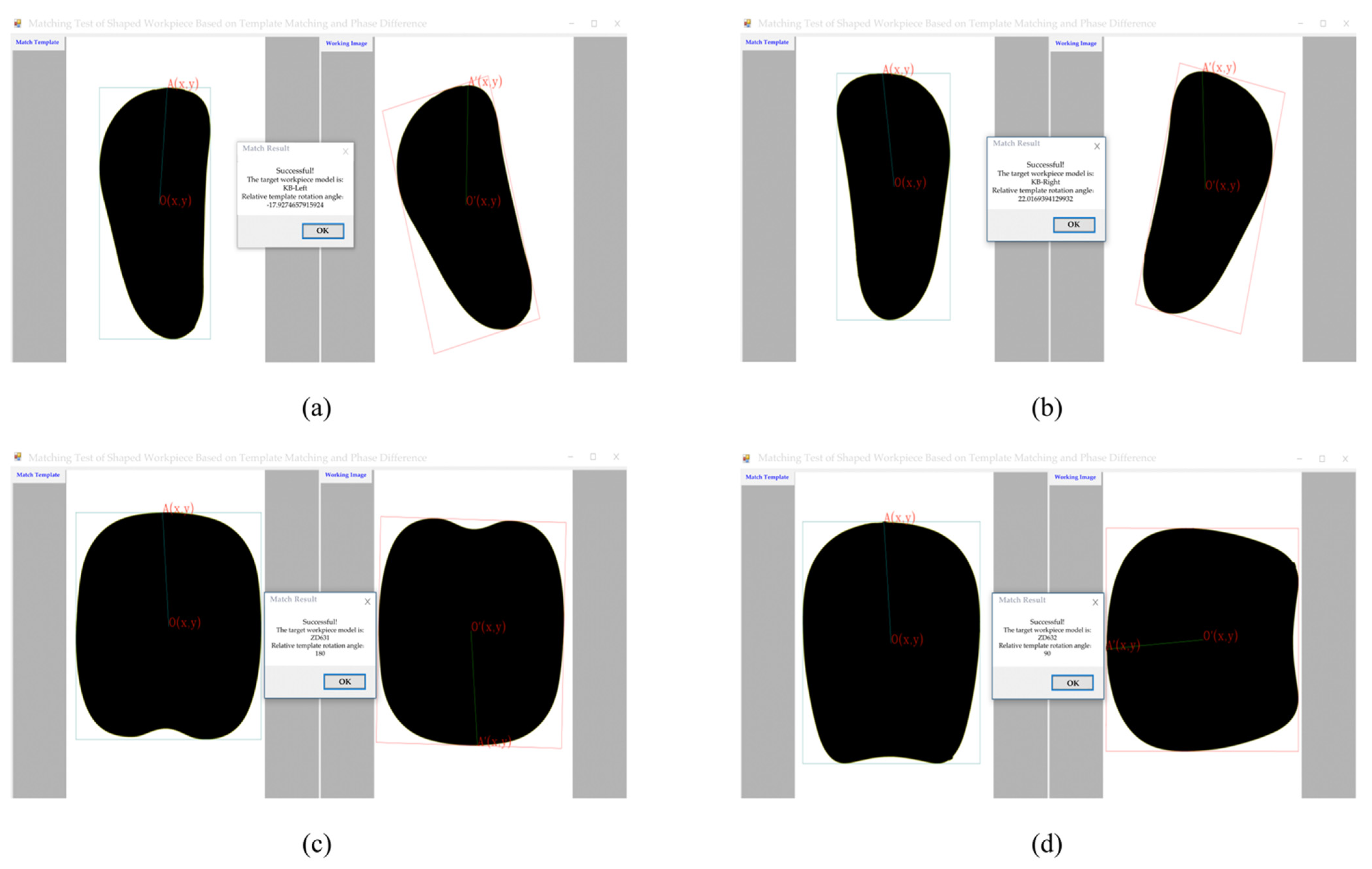
| KB-Left | −18 | KB-Left | −17.9275 | 0.40% | −18.0098 | 0.05% |
| KB-Right | 22 | KB-Right | 22.0169 | 0.07% | 22.2304 | 1.04% |
| ZD631 | 180 | ZD631 | 180 | 0 | 0 | 100% |
| ZD632 | 90 | ZD632 | 90 | 0 | 0 | 100% |
Publisher’s Note: MDPI stays neutral with regard to jurisdictional claims in published maps and institutional affiliations. |
© 2022 by the authors. Licensee MDPI, Basel, Switzerland. This article is an open access article distributed under the terms and conditions of the Creative Commons Attribution (CC BY) license (https://creativecommons.org/licenses/by/4.0/).
Share and Cite
Su, S.; Wang, J.; Zhang, D. Irregular Workpiece Template-Matching Algorithm Using Contour Phase. Algorithms 2022, 15, 331. https://doi.org/10.3390/a15090331
Su S, Wang J, Zhang D. Irregular Workpiece Template-Matching Algorithm Using Contour Phase. Algorithms. 2022; 15(9):331. https://doi.org/10.3390/a15090331
Chicago/Turabian StyleSu, Shaohui, Jiadong Wang, and Dongyang Zhang. 2022. "Irregular Workpiece Template-Matching Algorithm Using Contour Phase" Algorithms 15, no. 9: 331. https://doi.org/10.3390/a15090331
APA StyleSu, S., Wang, J., & Zhang, D. (2022). Irregular Workpiece Template-Matching Algorithm Using Contour Phase. Algorithms, 15(9), 331. https://doi.org/10.3390/a15090331