Abstract
In view of the characteristics of the guidance, navigation and control (GNC) system of the lunar orbit rendezvous and docking (RVD), we design an auxiliary safety prediction system based on the human–machine collaboration framework. The system contains two parts, including the construction of the rendezvous and docking safety rule knowledge base by the use of machine learning methods, and the prediction of safety by the use of the base. First, in the ground semi-physical simulation test environment, feature extraction and matching are performed on the images taken by the navigation surveillance camera. Then, the matched features and the rendezvous and docking deviation are used to form training sample pairs, which are further used to construct the safety rule knowledge base by using the decision tree method. Finally, the safety rule knowledge base is used to predict the safety of the subsequent process of the rendezvous and docking based on the current images taken by the surveillance camera, and the probability of success is obtained. Semi-physical experiments on the ground show that the system can improve the level of intelligence in the flight control process and effectively assist ground flight controllers in data monitoring and mission decision-making.
1. Introduction
As the only natural satellite of the Earth, the importance of the Moon to the Earth and mankind is self-evident. The Cislunar environment is a promising location for space exploration. Apollo carried out eight crewed manual lunar orbital rendezvous and docking missions, in which human intelligence played an important role in rendezvous monitoring and docking [1]. Space rendezvous and docking technology refers to the technology in which the chaser spacecraft and the target spacecraft meet at a certain position on the same orbit at a certain time, and then are structurally connected. Compared with traditional rendezvous and docking relying on ground control, autonomous rendezvous and docking can reduce the work intensity of ground personnel, eliminate the influence of signal delay and avoid external interference. Autonomous rendezvous and docking mean that the two spacecraft rely on their own navigation, guidance and control systems to complete the entire process of rendezvous and docking without the intervention of personnel on the ground or in the spacecraft [2,3]. An autonomous rendezvous requires the formulation of high-precision, high-reliability and high-safety rendezvous strategies, and higher requirements for the performance and intelligence of the guidance, navigation and control system [4,5,6]. The composition of an autonomous rendezvous and docking system is shown in Figure 1.
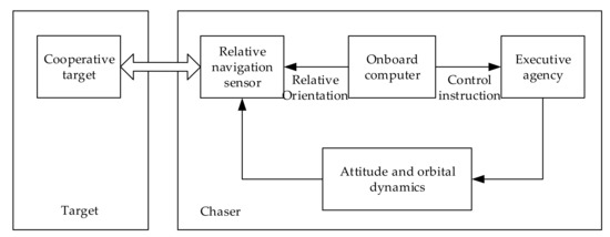
Figure 1.
Autonomous rendezvous and docking system.
The guidance, navigation and control for close operations of spacecraft has always been a hot research topic in the field of space technology. For example, Bucci et al. [7] and Bucchioni et al. [8] focused their attention on approaches to rendezvous in lunar Near Rectilinear Halo Orbits (NRHO). Colagrossi et al. [9] designed a GNC system for 6 degrees of freedom (6DOF) coupled Cislunar rendezvous and docking. Research on the Orion vehicle has also been conducted [10,11]. There are many rendezvous and docking strategies. In the close-range phase, the glideslope trajectory is known as a simple approaching trajectory complying to safety constrains, and the common approach directions are known as V-bar and R-bar [12,13]. Techniques such as sliding mode control [14], artificial potential function [15], genetic algorithms [16], searching strategy [17] and model predictive control [18] are all involved in the research field of rendezvous and docking. In this paper, we design an auxiliary system to predict the safety level of the rendezvous and docking process.
In the control process of the ground flight for autonomous rendezvous and docking missions in the third phase of lunar exploration, by drawing lessons the idea of solving the problem of scale ambiguity in the relative pose estimation of non-cooperative targets with the combination of monocular camera and LIDAR [19], we perform feature matching, extraction and target classification on the target image captured by the surveillance camera on the chaser. We design an auxiliary prediction system for engineering applications, which can improve the intelligent level of flight control, effectively assist ground personnel in data monitoring and mission decision-making and increase the mission success rate.
The remainder of this paper is organized as follows. In Section 2, we clarify the mission objectives, and analyze the needs and difficulties. In Section 3, we propose a framework for the autonomous judgment of human–machine collaboration safety and give the system’s function division and design scheme. Section 4 describes the experimental verification of the system. Section 5 is the conclusion.
2. Mission Objectives and Characteristics
2.1. Mission Objectives
During rendezvous and docking in the lunar orbit, the navigation surveillance camera configured on the chaser is used to monitor and observe the rendezvous and docking process of the two spacecraft. After entering the phase of ground measurement and control, we use surveillance cameras to perform target imaging, feature points extraction, tracking and matching and safety prediction. To accomplish the mission, the following problems need to be solved:
- Image feature detection and matching in uncertain environments. It needs to use image information to capture the target and extract related feature points, and further calculate the relative position and attitude of the two spacecraft;
- Safety prediction and judgment of the docking process. It needs to construct a knowledge base for safety judgments, predict the possible docking process in the current pose and evaluate the probability of successful docking;
- Visualized data to assist flight controllers in carrying out status analysis and mission decision-making. It is not only necessary to output the rendezvous safety judgment result, but also to visually display the safety judgment basis and criteria.
2.2. Mission Characteristics
The space rendezvous and docking optical navigation uses the cooperative target vision measurement method to obtain the relative position and attitude between the target coordinate system and the chaser [20,21], and the calculation method is the linear transformation method or the space rear intersection method [22]. The literature [23,24] shows that to extract features and recognize the target in a space environment, the uncertainty and influencing factors come from the following three aspects: imaging noise, geometric distortion and scene complexity. The imaging noise can be tested on the ground to find an appropriate image filtering and denoising algorithm [25,26].
Geometric distortion is a key issue that affects measurement accuracy. Taking into account the changes in the imaging environment before and after launch, this distortion is difficult to accurately calibrate on the ground. It needs to be adaptively calibrated according to the structure information of the imaging target during the measurement process, which can overcome the effects of distortion to some extent [23].
How to distinguish the target from the complex and changeable background is an important issue in the research of target recognition. The scene of the space target is relatively simple, and there is a clear distinction between the foreground and the background. However, the scale and posture of the space target in the scene vary greatly. During the process of rendezvous and docking, the distance of the target in the scene can vary from several thousand kilometers to less than 1 m [27], and the brightness of the target is affected by the direction of the sun, the direction of sight, the normal direction of the target surface and self-occlusion, resulting in a wide range of uneven brightness changes [2]. On the other hand, due to the constraints of factors such as space environment, power consumption and volume, the devices and processors that make up the computing platform on the spacecraft are highly reliable but have low operating frequencies. In order to meet the real-time nature of the control system, there are very high requirements for the efficiency of image processing and analysis algorithms [4].
3. Human–Machine Collaborative Self-Judgment Framework for Safety of RVD
3.1. System Framework Design
The self-judgment process for rendezvous and docking safety is divided into the following two parts: safety knowledge base construction and safety prediction.
The purpose of the safety knowledge base construction is to learn the knowledge base. In addition, the generation of training samples is mainly based on the 6DOF relative position and attitude data generated using the relative dynamics model of the spacecraft. The self-judgment framework for the safety of the rendezvous and docking is shown in Figure 2. We first establish the attitude dynamics model of the multi-body spacecraft and dynamics model of the lunar orbit [28]. Then, under each relative position and attitude, an image sequence is generated according to the internal parameters of the camera and the mechanical structure of the docking surface of the target. After feature selection and matching, a set of rules that can be used for training a decision tree of the safety knowledge base can be obtained. Finally, we can obtain the safety judgment knowledge base by training the decision tree.
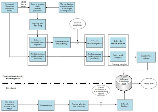
Figure 2.
Self-judgment framework for safety of RVD.
The purpose of safety prediction is to predict the safety level of the rendezvous and docking process. In the process of safety prediction, the features of the images taken by the camera are matched with the simulated image’s features. After the feature matching is manually evaluated, if there are more than six feature points forming an effective match, these features and the safety knowledge base are used to judge the safety level of the rendezvous and docking.
3.2. Feature Selection and Matching of the Target Image
It can be seen from Figure 2 that the feature extraction and selection of the target image is a key issue in system design. The surveillance camera is a monocular uncalibrated visible light camera. Since the surveillance camera is used to monitor the target, it should meet the requirements of imaging the entire target at a relatively long distance, and imaging notable regions at medium and short distances. The resolution of the camera affects the image clarity, the position error of extracted features and ultimately affects the accuracy of pose information and safety prediction. A low resolution will greatly affect the accuracy of the results. The field of view of the camera determines the closest distance to image the entire target or some notable regions of the target. A small field of view will make the proposed method inapplicable at a close range. Thus, based on the test environment, we set the camera resolution to 2048 × 2048, pixel size to 5.5 um × 5.5 um, focal length to 20 mm, field of view to 20° × 20° and frame rate to 10 FPS. During the imaging process, it can be self-calibrated according to the known structure model of the measured target. The target relative working distance is 30~0.3 m, and the speed is 0.3 m/s. Due to the limitation of the depth of field, the camera cannot clearly image the target at a distance of 20 m. Therefore, it is difficult to ensure the matching accuracy through the traditional method of extracting points, lines and surfaces.
In this regard, this paper divides the feature extraction, matching and application process on the target image into the following steps:
- Manually select several positions on the mechanical structure model of the end face of the target. These positions have precise coordinates on the mechanical structure drawing and can be extracted using the Scale-Invariant Feature Transform (SIFT) features [29];
- Convert the position specified on the mechanical structure drawing to the (sub) pixel position on the simulated image by using the rotation matrix and displacement vector generated by the dynamics model;
- Extract the SIFT features from the real images collected in the test environment and the simulated images, and form feature point pairs;
- In the construction stage of the safety knowledge base, the features on the images collected by the surveillance cameras are clustered, and the feature cluster centers are matched with the features on the simulated images. Then, the matching results are manually detected, and the false matches are deleted. Since the safety level corresponding to the simulated image can be obtained from the dynamics model, the label for the manually detected features can be obtained, which is the same as the matched simulated image. With the features and label, we can construct several training samples. Then, decision tree methods are used to construct a knowledge base. An example of the feature points is shown in Figure 3;
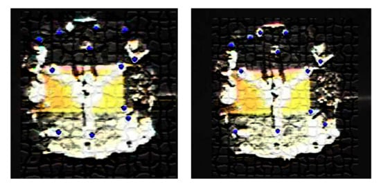 Figure 3. The feature points that are detected and matched by using feature clustering when the chaser approaches the target (The picture is mosaic-processed).
 - In the test stage, we first collect images using the surveillance camera, and then extract features and cluster them. After that, we manually detect the number of clusters and the degree of feature aggregation within the cluster and select the cluster centers. Finally, we obtain the safety level by inputting the filtered cluster centers into the decision tree.
We select the cluster centers of the features manually and input them into the decision tree. The selection is based on the manually selected notable positions on the target. Due to the specific characteristics of space missions, we can manually select some easily identified positions on the target. In this way, we can easily find the corresponding positions on the target image. The disadvantage of this kind of manual selection is that we need to find notable positions for each specific mission. However, due to the specific characteristics of space missions, manual point selection will not be a frequent task. The advantage is that we only need the image as the input in our model and do not need other data that are measured by specific devices.
3.3. Safety Judgment Knowledge Base
The construction of the safety judgment knowledge base includes two steps, namely, the classification of safety levels and the training of decision trees.
3.3.1. The Classification of Safety Levels
The spacecraft dynamics model is used to generate the simulated trajectory sequence and the deviation of the rendezvous and docking result. The deviation of the rendezvous and docking result includes three displacement deviations and three attitude angle deviations. Assuming that these six random variables obey the normal distribution of different parameters, the six deviations are set to four levels according to the standard deviation of their distribution. We obtain 1500 sets of simulated rendezvous and docking deviation results by using the spacecraft dynamics model to simulate the rendezvous and docking process 1500 times. Figure 4 and Figure 5 show the deviation of displacement in the x direction and the rotation angle as examples. Each blue cross represents the deviation of one simulation result. The mean and standard deviation of each deviation are shown in Table 1. In the table, , and denote the deviations of the movements in the direction of x, y and z, respectively, and , and denote the deviations of precession angle, nutation angle and rotation angle, respectively.
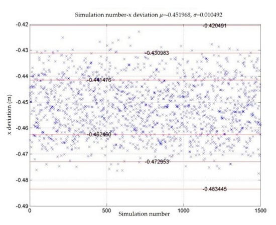
Figure 4.
x deviation of rendezvous and docking results and distribution of .
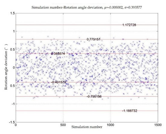
Figure 5.
Rotation angle deviation of rendezvous and docking results and distribution of .

Table 1.
Statistics of 6 degrees of freedom deviations from 1500 sets of rendezvous and docking results of spacecraft dynamics simulation.
The safety level of the one deviation of the rendezvous and docking result is calculated by the following equation:
where is the deviation, denotes the mean and denotes the standard deviation. The final safety level of the rendezvous and docking is obtained by taking the maximum value of safety levels for the 6DOF deviations, as follows:
where denote the safety level for x, y and z, and , and deviations, respectively.
3.3.2. Training of Decision Trees
We first extract features ( from the simulated RGB image sequence generated by using the spacecraft dynamics simulation model, and also obtain the deviation of the rendezvous and docking result corresponding to this sequence. Here, denotes the simulated image at time in the i-th rendezvous and docking experiment. Then, we convert the deviation into a safety level by using Equation (1). Thus, we can obtain the sample by treating the safety level as a label. After simulating several times, the generated samples are finally used to train the decision tree. In the real rendezvous and docking experiment, after capturing the image of the docking surface of the target using the security surveillance camera installed on the chaser, we extract the features and use the safety judgment knowledge base to determine the safety level corresponding to the current state.
The safety judgment knowledge base is constructed using an Ordinary Binary Classification Tree (OBCT). The sample set is divided into a training set (90%) and a validation set (10%), and a cross-validation technique is used as the stopping criterion in the training of the decision tree. The algorithm flow of the training of the decision tree is shown in Figure 6. We continuously select the best features to split the node until the average classification error of all validation sets is minimized. Finally, we obtain a decision tree with a depth of 50. During training, the maximum entropy impurity reduction (information gain) strategy is used to select the optimal feature components. The entropy impurity at node of the decision tree is , and the information gain obtained by selecting features is , as follows:
where indicates the frequency of samples belonging to the category at the node in the total number of samples, and are the left and right child node of , respectively, and are the corresponding impurities, and is the probability that the tree grows from to when the feature is selected.

Figure 6.
Decision tree training algorithm process.
After training the decision tree, we further generate a test set of 150 samples and show the confusion matrix in Table 2. The classification error on this test set is 6%.

Table 2.
The confusion matrix of the test set.
4. System Verification Process
The nine-degrees-of-freedom turntable system is used to simulate the approaching process of the two spacecraft at a relative distance of 30 m to 0.3 m. The setup of the experimental system is shown in Figure 7.
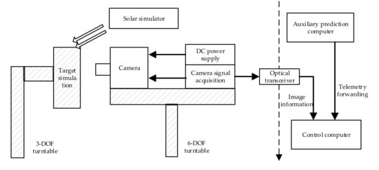
Figure 7.
Diagram of a semi-physical experiment system.
The target docking surface model is installed on the target platform, and the camera is installed on the chaser platform. The image signal is transmitted to the control computer through the optical transceiver, and the control computer encapsulates the received video data in real time by simulating the flight control network protocol and then uses the local area network to forward it to the auxiliary prediction computer. In addition, in the experiment, the incident angle of sunlight under the real lunar orbit is simulated, and a solar simulator with a three-degrees-of-freedom servo is used to generate parallel light to illuminate the entire target plane.
The data display and human–computer interaction interface is shown in Figure 8. The data display areas show the trajectories of the target in different views. When a rendezvous and docking operation ends (regardless of whether it ends normally or abnormally), the 6DOF rendezvous and docking deviations are obtained, and a sample is also generated. In the process of rendezvous and docking, the mathematical simulator outputs six degrees of freedom at each moment. According to the small hole imaging model and the internal parameters of the camera, a simulated image is generated from the mechanical model of the target end face. is then obtained by extracting features from. By using Equation (2), the rendezvous and docking deviation are mapped to a safety level. With the features and the corresponding safety level, we can construct the training samples to train the decision tree. The whole process realizes the transformation from image to rendezvous and docking safety level . At the test experiments, the surveillance camera takes an image of the target, as shown on the left side of Figure 8, and the decision tree predicts the safety level of the rendezvous and docking, which is displayed in text in Figure 8. The four safety levels mean “Normal”, “Early Warning”, “Warning” and “Abnormal”, respectively. In order to visually display the real-time status of the rendezvous and docking, the position of the target is shown in Figure 8 in different views with a red cross.
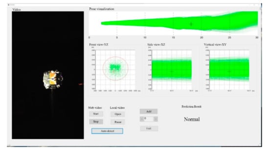
Figure 8.
Data display and human–computer interaction interface.
A nine-degrees-of-freedom turntable is used to run 50 sets of rendezvous and docking trajectories, and the results of safety judgments using the above methods are shown in Table 3.

Table 3.
Safety verification test results of a nine-degrees-of-freedom turntable rendezvous and docking.
5. Conclusions
This paper designs an auxiliary prediction system for the lunar orbit autonomous rendezvous and docking process based on a human–machine collaboration framework. It can use the monitoring camera telemetry information in the flight control phase to capture the characteristics of the target and track the target, and to identify the relative relationship between the chaser and the target, analyze whether the relative position and attitude of the spacecraft meet the safety range of docking and assist in predicting the safety of the docking process.
The relevant ground experiments show that the system can intuitively and comprehensively indicate the relative relationship between two spacecraft, improve the human–machine collaboration effect in the flight control phase and effectively assist the ground flight controller of the GNC system in status analysis and mission decision-making.
Author Contributions
Conceptualization, D.Y. and P.L.; methodology, D.Y.; software, D.Y. and D.Q.; validation, D.Y., P.L. and D.Q.; formal analysis, D.Y. and P.L.; investigation, P.L. and D.Q.; resources, D.Q. and X.T.; data curation, D.Y.; writing—original draft preparation, D.Y.; writing—review and editing, D.Y., P.L., D.Q. and X.T.; visualization, D.Y. and D.Q.; supervision, P.L. and X.T.; project administration, X.T.; funding acquisition, P.L. and X.T. All authors have read and agreed to the published version of the manuscript.
Funding
This research was funded by the Key Program of the Natural Science Foundation of China under Grant 51935005, Basic Research Program under Grant JCKY20200603C010, and Science and Technology on Space Intelligent Control Laboratory under Grant ZDSYS-2018-02.
Institutional Review Board Statement
Not applicable.
Informed Consent Statement
Not applicable.
Data Availability Statement
Not applicable.
Conflicts of Interest
The authors declare no conflict of interest.
References
- Zhu, R.Z.; Wang, H.F.; Cong, Y.T.; Wang, R. Comparative Study of Chinese and Foreign Rendezvous and Docking Technologies. Spacecr. Eng. 2013, 22, 8–15. [Google Scholar]
- Fehse, W. Automated Rendezvous and Docking for Spacecraft; Cambridge University Press: New York, NY, USA, 2003; pp. 1–7. [Google Scholar]
- Woffinden, D.C.; Geller, D.K. Navigating the Road to Autonomous Orbital Rendezvous. J. Spacecr. Rockets. 2007, 44, 898–909. [Google Scholar] [CrossRef]
- Wang, Z.H.; Chen, Z.H.; Zhang, G.F.; Zhang, H.X. Automatic Test of Space Rendezvous and Docking GNC Software. In Proceedings of the 2012 International Conference on Information Technology and Software Engineering, Beijing, China, 8–10 December 2012; pp. 81–92. [Google Scholar]
- Dong, H.; Hu, Q.; Akella, M.R. Safety Control for Spacecraft Autonomous Rendezvous and Docking Under Motion Constraints. J. Guid. Control Dyn. 2017, 40, 1680–1692. [Google Scholar] [CrossRef]
- Guglieri, G.; Maroglio, F.; Pellegrino, P.; Torre, L. Design and Development of Guidance Navigation and Control Algorithms for Spacecraft Rendezvous and Docking Experimentation. Acta Astronaut. 2014, 94, 395–408. [Google Scholar] [CrossRef]
- Bucchioni, G.; Innocenti, M. Rendezvous in Cis-Lunar Space near Rectilinear Halo Orbit: Dynamics and Control Issues. Aerospace 2021, 8, 68. [Google Scholar] [CrossRef]
- Bucci, L.; Colagrossi, A.; Lavagna, M. Rendezvous in Lunar near Rectilinear Halo Orbits. Adv. Astronaut. Sci. Technol. 2018, 1, 39–43. [Google Scholar] [CrossRef][Green Version]
- Colagrossi, A.; Pesce, V.; Bucci, L.; Colombi, F.; Lavagna, M. Guidance, Navigation and Control for 6DOF Rendezvous in Cislunar Multi-Body Environment. Aerosp. Sci. Technol. 2021, 114, 106751. [Google Scholar] [CrossRef]
- Muñoz, S.; Christian, J.; Lightsey, E.G. Development of an End to End Simulation Tool for Autonomous Cislunar Navigation. In Proceedings of the AIAA Guidance, Navigation, and Control Conference, Chicago, IL, USA, 10–13 August 2009; pp. 1–21. [Google Scholar]
- D’Souza, C.; Crain, T.; Clark, F.; Getchius, J. Orion Cislunar Guidance and Navigation. In Proceedings of the AIAA Guidance, Navigation and Control Conference and Exhibit, Hilton Head, SC, USA, 20–23 August 2007; pp. 1–21. [Google Scholar]
- Hablani, H.B.; Tapper, M.L.; Dana-Bashian, D.J. Guidance and Relative Navigation for Autonomous Rendezvous in A Circular Orbit. J. Guid. Control Gyn. 2002, 25, 553–562. [Google Scholar] [CrossRef]
- Ariba, Y.; Arzelier, D.; Urbina, L.S.; Louembet, C. V-bar and R-bar Glideslope Guidance Algorithms for Fixed-Time Rendezvous: A Linear Programming Approach. IFAC Papaers Online 2016, 49, 385–390. [Google Scholar] [CrossRef]
- Ghosh Dastidar, R. On the Advantages and Limitations of Sliding Mode Control for Spacecraft. In Proceedings of the AIAA SPACE 2010 Conference & Exposition, Anaheim, CA, USA, 30 August–2 September 2010; p. 8777. [Google Scholar]
- Lopez, I.; Mclnnes, C.R. Autonomous Rendezvous Using Artificial Potential Function Guidance. J. Guid. Control Gyn. 1995, 18, 237–241. [Google Scholar] [CrossRef]
- Kim, Y.H.; Spencer, D.B. Optimal Spacecraft Rendezvous Using Genetic Algorithms. J. Spacecr. Rocket. 2002, 39, 859–865. [Google Scholar] [CrossRef]
- Francis, G.; Collins, E.; Chuy, O.; Sharma, A. Sampling-Based Trajectory Generation for Autonomous Spacecraft Rendezvous and Docking. In Proceedings of the AIAA Guidance, Navigation, and Control Conference, Boston, MA, USA, 19–22 August 2013; p. 4549. [Google Scholar]
- Mammarella, M.; Capello, E.; Guglieri, G. Robust Model Predictive Control for Automated Rendezvous Maneuvers in Near-Earth and Moon Proximity. In Proceedings of the 2018 AIAA SPACE and Astronautics Forum and Exposition, Orlando, FL, USA, 17–19 September 2018; p. 5343. [Google Scholar]
- Hao, G.T.; Du, X.P.; Zhao, J.G.; Song, J.J. Relative Pose Estimation of No cooperative Target Based on Fusion of Monocular Vision and Scanner less 3D LIDAR. J. Astronaut. 2015, 36, 1178–1186. [Google Scholar]
- Bujnak, M.; Kukelova, Z.; Pajdla, T. A General Solution to the P4P Problem for Camera with Unknown Focal Length. In Proceedings of the IEEE Conference on Computer Vision and Pattern Recognition, Anchorage, AK, USA, 24–26 June 2008; pp. 1–8. [Google Scholar]
- Wu, F.C.; Wang, Z.H.; Hu, Z.Y. Cayley Transformation and Numerical Stability of Calibration Equation. Int. J. Comput. Vis. 2009, 82, 156–184. [Google Scholar] [CrossRef]
- Lepetit, V.; Moreno-Noguer, F.; Fua, P. EPnP: An Accurate O(n) Solution to the PnP Problem. Int. J. Comput. Vis. 2009, 81, 156–166. [Google Scholar] [CrossRef]
- Zhang, S.J.; Cao, X.B.; Zhang, F.; He, L. Monocular Vision Algorithm of Three Dimensional Position and Attitude Localization Based on Feature Points. Sci. China-Inf. Sci. 2010, 40, 591–604. [Google Scholar]
- Zhou, J.; Bai, B.; Yu, X.Z. A New Method of Relative Position and Attitude Determination for Non-Cooperative Target. J. Astronaut. 2011, 32, 516–521. [Google Scholar]
- Mafi, M.; Martin, H.; Cabrerizo, M.; Andrian, J.; Barreto, A.; Adjouadi, M. A Comprehensive Survey on Impulse and Gaussian Denoising Filters for Digital Images. Signal Process. 2019, 157, 236–260. [Google Scholar] [CrossRef]
- Tian, C.; Xu, Y.; Fei, L.; Yan, K. Deep Learning for Image Denoising: A Survey. In Proceedings of the Twelfth International Conference on Genetic and Evolutionary Computing, Changzhou, China, 14–17 December 2018; pp. 563–572. [Google Scholar]
- Wertz, J.R.; Bell, R. Autonomous Rendezvous and Docking Technologies: Status and Prospects. In Space Systems Technology and Operations; International Society for Optics and Photonics: Orlando, FL, USA, 2003; pp. 20–30. [Google Scholar]
- Zhang, R.W. Satellite Orbit Attitude Dynamics and Control; Beijing University of Aeronautics and Astronautics Press: Beijing, China, 1998; pp. 297–302. [Google Scholar]
- Lowe, D.G. Distinctive Image Features from Scale-Invariant Keypoints. Int. J. Comput. Vis. 2004, 60, 91–110. [Google Scholar] [CrossRef]
Publisher’s Note: MDPI stays neutral with regard to jurisdictional claims in published maps and institutional affiliations. |
© 2021 by the authors. Licensee MDPI, Basel, Switzerland. This article is an open access article distributed under the terms and conditions of the Creative Commons Attribution (CC BY) license (https://creativecommons.org/licenses/by/4.0/).