1. Introduction
End surfaces of rotary bodies are widely used as working surfaces of actuators in modern automotive and mechanical engineering. These include conical disks of continuously variable transmission of automatic transmissions of cars, parts of end bearings (both tapered and axial) [
1,
2,
3,
4], valves of gas-distributing mechanisms of internal combustion engines, and so on. These surfaces are usually exposed to high operating temperatures and specific pressures [
5,
6].
Using plastic deformation of the surface to form a regular microrelief on the conjugated working surfaces of heavily loaded friction pairs allows enhancing their durability [
7,
8,
9,
10].
Fundamental in terms of findings obtained in the study of the influence of rolling modes on the surface layer structure of the treated surface is work [
11]. The authors established the influence of burnishing force and rolling feed on the roughness parameters of the rolled surface. In addition, the authors investigated residual stresses in-depth (in the axial direction) at different feed rates of rolled materials (prediction of residual stresses (in the axial direction) for different burnishing feed rates, along with depth).
The result of comparing the structure of the material obtained by ball burnishing and shifted in the axial direction of the roller allowed us to systematize the influence of technological parameters and structural components of the material.
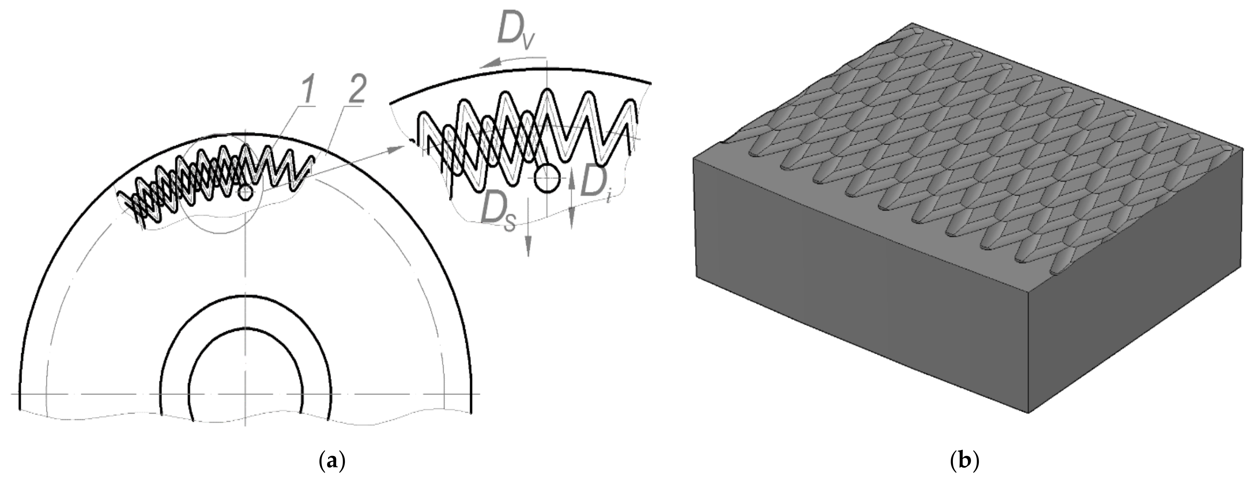
Specific parameters of the relative area of burnishing are challenging to provide when grooves of partially regular microrelief (PRMR) of the 3rd type are formed, which are characterized by an overlap of the groove. Therefore, the formation of PRMR of the 3rd type with a given relative area of burnishing on the rotary body end surfaces (RBES) is a rather complex technological task.
The formation of a regular microrelief on the conjugated working surfaces of heavily loaded friction pairs significantly enhances their functional properties and, accordingly, the service life of the unit itself [
12,
13,
14]. The regular microrelief’s positive effect on the surface roughness parameters is also described in [
15]. A regular microrelief was formed on the outer cylindrical surfaces of specimens from medium-carbon steel 1C45 and low-carbon alloy steel 18CrMn4-4, which were used to determine the effect of processing conditions on the surface roughness and hardness. One of the leading research findings was that a significant influence of the vibration amplitude was found to be the most determining factor for the surface roughness parameter
Ra.
In [
16], the effect of changes in the deformation force and feed rate on the surface roughness parameters during burnishing and the mechanical properties of the surface layer was investigated. In addition, surface parameters obtained by ball burnishing and milling were compared. The range of optimal pressure values at the processing of specimens by ball burnishing (ball burnishing treatment), at which values of roughness parameters will be minimal, was established.
In [
17], the relative area of the regular microrelief (RMR)
Fn was presented as the ratio of the area occupied by regular roughness
Fgr to the surface area of the part to be processed
Fw. According to [
1], the relative surface area
Fn was a partially regular microrelief parameter, which most fully characterizes almost all the surface’s functional properties and, primarily, the actual contact area of one surface.
Therefore, the regular microrelief Fn’s relative surface area was one of its most important indicators, which characterizes the working properties of the surface on which it is formed. Its optimal value varies between 30–45% depending on the conjugated surfaces’ operating conditions [
18]. The optimal relative areas of burnishing of the regular microrelief depending on the operating conditions of the machine parts’ cylindrical surfaces were studied in detail in [
19,
20,
21]. Such relative areas of burnishing are determined by the optimal value of the relative reference length of the profile top [
22]. This value is defined as the ratio of the reference length of the profile to its base length. The Abbott–Firestone curve can describe the relationship between surface performance and roughness parameters. This relationship was described in [
23]. The performance characteristics of the surface were evaluated not by the surface roughness, but the parameters of the Abbott–Firestone curve. According to the authors, the above three parameters determined from the Abbott–Firestone curve (
Rpk,
Rk and
Rvk) illustrate the surface texture’s ability to resist friction.
Peculiarities of evaluating the surface condition by the Abbott–Firestone curve parameters are described in [
24]. The authors have found that surface integrity illustrates the relationship between the surface’s required functional properties and changes in the new surface properties. The surface can be evaluated using two fundamental properties: The spatial arrangement of the surface (surface roughness) and the surface layer’s physicochemical properties. To determine the burnishing area of a partially regular microrelief of the 3rd type formed on the rotary body end surface with V-shaped grooves, which were shifted by an angular pitch of 0.5°, it was necessary to determine the overlap area of PRMR grooves [
25]. PRMR grooves of the 3rd type with a large degree of overlap significantly reduce the microrelief’s total area and, accordingly, the relative area of vibration. Studies in this area focus mainly on determining the relative area of burnishing and the influence of the grooves’ geometric parameters and arrangement.
In [
26,
27], the formation of a regular microrelief on profile surfaces with different geometric parameters depending on the formation conditions was considered. The authors conducted a full-factor experiment with four variables: The diameter of the deforming element, the deformation force, the amplitude of the deforming element, and the number of oscillations. According to the research findings, Pareto histograms were constructed, which show that the number of oscillations and the deforming element amplitude significantly influence changes in the shape of the regular microrelief cells.
The authors of [
28] presented the results obtained with the experimental tool L8 Taguchi, which was used to form a regular microrelief on planar surfaces. The parameters that significantly affect the process of forming a regular microrelief using a CNC milling machine on flat surfaces were determined. By changing the processing modes, regular microreliefs of different sizes were formed, on which the orientation of grooves was different. Such an element of the forming mode as the feed was also used.
A comparative analysis of different types of regular microrelief was conducted subject to the condition of forming the largest area of contact with the liquid [
29]. RMR types, such as concave cones, spherical holes, and longitudinal lines, were compared. It was found that with other identical parameters, the microrelief represented by conical holes was the most optimal. The smallest area of contact with the liquid was provided by a microrelief represented by a plurality of holes of concave spherical shape. The area of triangular grooves, depending on the groove’s geometric parameters and their location on the rotary body end surfaces, was calculated in [
30].
The authors of [
31], Barauskiene O. and Zyhulia S., developed an algorithm for the technological process of forming geometric parameters of a partially regular microrelief by burnishing on the outer cylindrical surface of printing equipment. The influence of technological factors on changes in the surface area with partially regular microrelief was established. The limits and conditions of possible variation of the relative surface area were determined to enhance the performance of the printing equipment parts. In [
32], the control algorithm was developed for the technological process of forming microrelief guides by a method of fine plastic deformation applied to flat surfaces of the printing equipment parts. The proposed technology allows increasing the wear resistance of flat guides and improving printed products’ positioning when passing the surface of micro guides of printed products. The developed algorithm includes a set of indicators related to the material, geometric, and physicomechanical parameters of the flat guide surface and plastic deformation conditions.
The problem of the overlap of the groove area was considered in [
33]. However, the author considered a sinusoidal type groove, which was approximated as a set of rectilinear sections. This method of approximation is quite inaccurate to determine the area of overlap. After analyzing scientific publications in the public domain, we can conclude that no studies have been carried out to determine the overlap area of V-shaped grooves formed on the regular or partially regular microrelief.
This research aims to determine the overlap area of the PMR grooves formed on the RBES and the influence of mutual placement and geometric parameters of the grooves.
3. Results
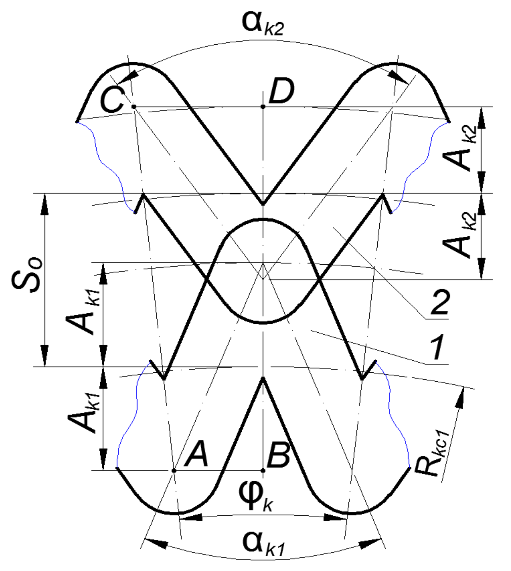
Consider the general case of the intersection of V-shaped grooves formed on rotary bodies’ end surfaces (
Figure 2). This will help us establish the dependent geometric parameters of the grooves and the relationship between them.
The relationships between groove parameters were as follows:
The angular pitch of the groove is determined from the equation:
where
Nel is the number of PRMR elements located on the RBES within the range of 360°.
We write down the equation for determining the angle α
k1Having solved the system of equations to determine α
k1, we obtain:
Similarly, we write down the equation to determine the angle α
k2:
Having solved the system of equations to determine α
k2, we obtain:
In addition, we can express angle α
k2 via angle α
k1. To do this, we make a system of equations from system of Equations (2) and (3).
Having solved this system of equations to determine α
k2, we obtain:
Thus, the obtained dependencies allow us to express the required geometric parameters using known quantities.
When analyzing the groove intersection process, seven stages of the intersection were found. In addition, the degree of overlap transforms from the intersection of the segmental parts of vertices to a complete intersection of rectilinear sections of the grooves.
Analytical dependences to determine the overlap area will be different at each stage, thus we consider each case separately.
It should also be noted that the overlap area of the grooves for cases I–IV was defined as the area of a complex figure formed by segments and trapezoids. The number of such areas will be equal to half the number of intersecting grooves.
For cases V–VII, the overlap area was defined as the area of intersecting diamonds. The number of such areas will be equal to the number of intersecting grooves.
Stage I. Consider the case when the groove vertices intersect within a circular segment with radius
and chord height Δ
ρ (
Figure 3).
The overlap area of two grooves was defined as the sum of their segments’ areas with the chord height Δ
ρ.The formula determines the chord height:
where
is the segment radius, mm;
So is the axial pitch of PRMR grooves, mm;
Ak is the amplitude of PRMR grooves, mm.
The formula determines angle
:
Taking into account (10), Formula (8) takes the following form:
The area of existence for this formula was determined by the limit value of the axial pitch of the PRMR, which was determined from the following dependence:
Stage II. Consider the case when the groove vertices intersect within the circular segment with radius
and chord height
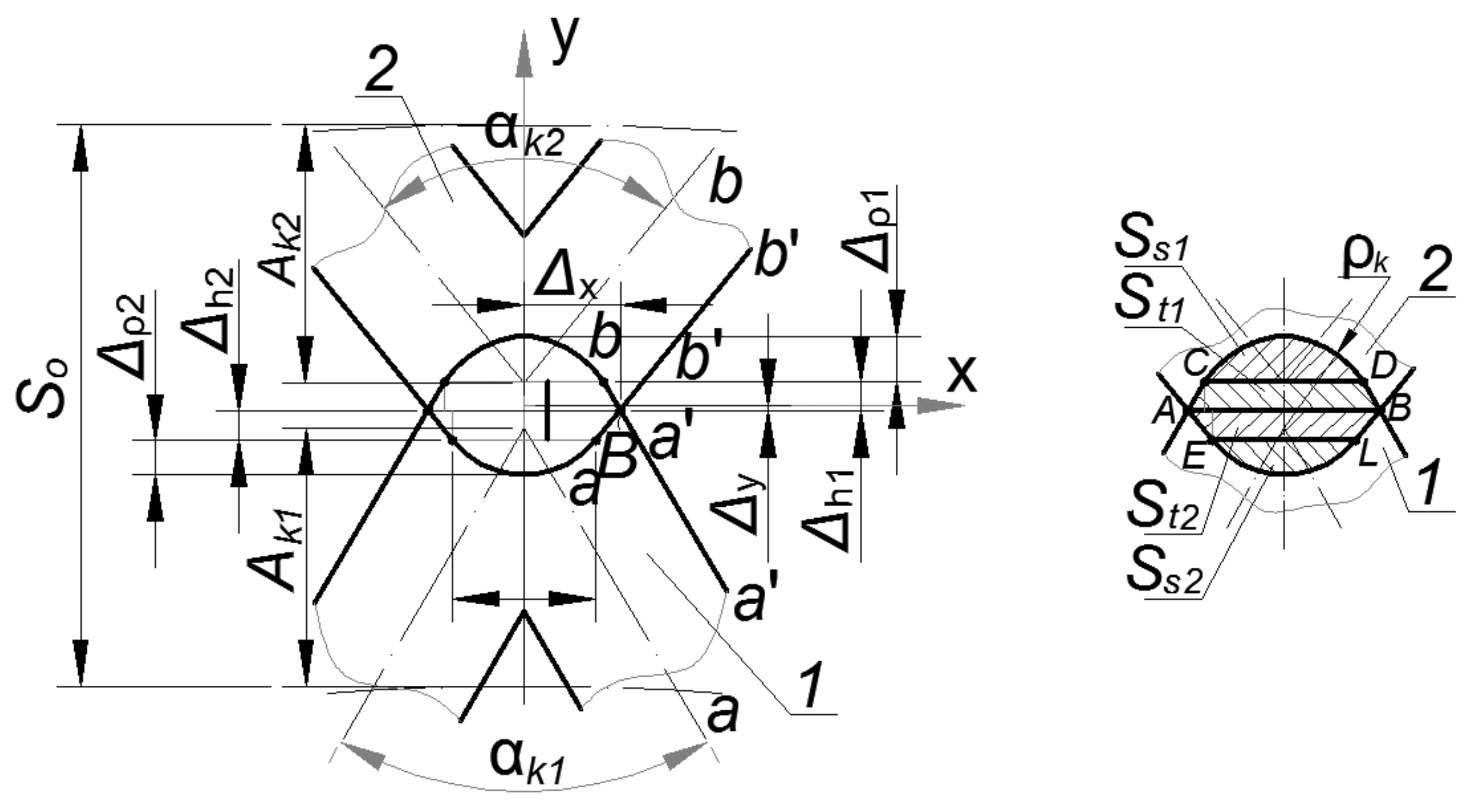
and partially rectilinear sections (
Figure 4).
We calculated the overlap area of the grooves for this case.
In this case, the overlap area will be defined as the sum of the areas of two circular segments with radius
and the areas of two trapezoids (
ACDB and
AELB) (
Figure 4).
where
Ss1 is the segment area of groove 1, mm
2;
St1 is the trapezoid area of groove 1, mm
2;
Ss2 is the segment area of groove 2, mm
2;
St2 is the trapezoid area of groove 2, mm
2.
To determine the overlap area according to the scheme (
Figure 4), it was advisable to determine the coordinates of point
B pertaining to the intersection of groove elements.
To do this, we wrote down the equation of the axial lines of grooves 1 and 2 in the coordinate system xy.
The equation of centerline
a–a (groove 1) is written in the following form:
The equation of centerline
b–b (groove 2) is written in the following form:
The equation of the imprint of side surface
a′
–a′ (groove 1) is written in the following form:
The equation of the imprint of side surface
b′
–b′ (groove 2) is written in the following form:
We equate expressions (16) and (17) to find value
, at which values
and
will be the same. That is, we find coordinate
x of point
B.
Substituting the obtained value into Formula (16), we obtain value
.
The formula determines the area of the
ACDB trapezoid:
where
at1 is the length of the lower base of trapezoid
AB formed by the intersection of two grooves, mm,
bt1 is the length of the lower base of trapezoid
CD formed by the intersection of two grooves, mm; Δ
h1 is the height of the trapezoid formed by the intersection of two grooves, mm.
Formula (20) for determining the area of trapezoid
ACDB is written as:
Taking into account Formula (18), Formula (22) will be written as follows:
Similarly, we find the area of trapezoid
ABLE.The formula found the area of the segment with the
CD chord:
The formula found the area of the segment with the
EL chord:
The area of existence for Formula (13) was determined by the limit value of the axial pitch of PRRM, which was determined by the dependence:
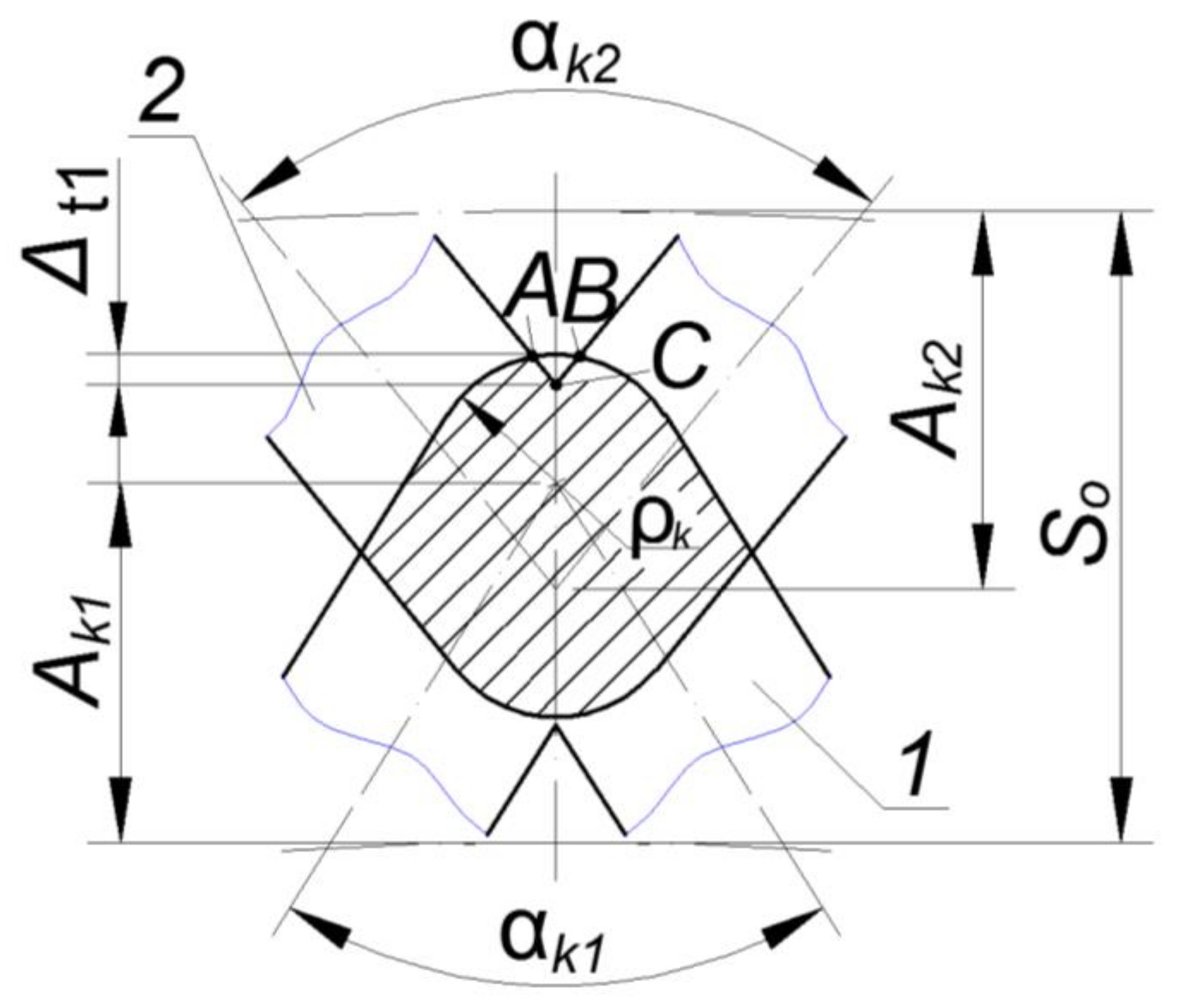
Stage III. Consider the option when the intersecting grooves formed one sector on top of one of the grooves (
Figure 5).
The overlap area for this case was calculated by Formula (13), taking into account the absence of the circular sector area with radius Δ
t1, which was determined by the formula:
where
Ss3 is the
ABC sector area of the circle formed by the intersection of grooves 1 and 2, mm
2.
The area of figures St1 was determined by Formula (23), St2—by Formula (25), Ss1—by Formula (26), Ss2—by Formula (27)
The formula determined the area of the
ABC sector:
where Δ
t1 is the radius of sector
ABC, mm.
The formula determined the sector radius:
Taking into account Formula (31), Formula (30) takes the following form:
The area of existence for this formula was determined by the limit value of the axial pitch of PRMR, which was determined from the dependence:
Stage IV. Consider the option when the intersecting grooves form circular sectors at the top of each groove (
Figure 6).
The overlap area for this case was calculated by Formula (13), taking into account the absence of the circular sector area with radii Δ
t1 and Δ
t2, which was determined by the formula:
where
Ss4 is the sector area of circle
DEF formed by the intersection of grooves 1 and 2, mm
2.
The area of figures St1 is determined by Formula (23), St2—by Formula (25), Ss1—by Formula (26), Ss2—by Formula (27), Ss3—by Formula (32).
The formula determined the area of the DEF sector:
where Δ
t2 is the radius of sector
DEF, mm.
The formula determined the sector radius:
Taking into account Formula (36), Formula (35) takes the following form:
The area of existence for this formula was determined by the limit value of the axial pitch of PRMR, which was determined from the dependence:
Stage V. Consider the option when the intersecting grooves form two intersecting diamonds (
Figure 7).
The overlap area for this case was calculated by Formula (13), taking into account the absence of the circular sector area with radii Δ
t1 and Δ
t2, which was determined by the formula:
The area of figures St1 is determined by Formula (23), St2—by Formula (25), Ss2—by Formula (27), Ss4—by Formula (37).
Area Δ
BCD was determined by the formula:
Taking into account Formula (31), Formula (40) takes the following form:
Area Δ
CDE was determined by the formula:
The length of segment
CD was determined by the formula:
The length of segment
CE can be found from the sine theorem.
Then Formula (42) for determining area Δ
CDE takes the following form:
Angle α
s is determined from dependence:
Taking into account Formulas (48) and (49), Formula (47) takes the following form:
The area of existence for this formula was determined by the limit value of the axial pitch of PRMR, which was determined from the dependence:
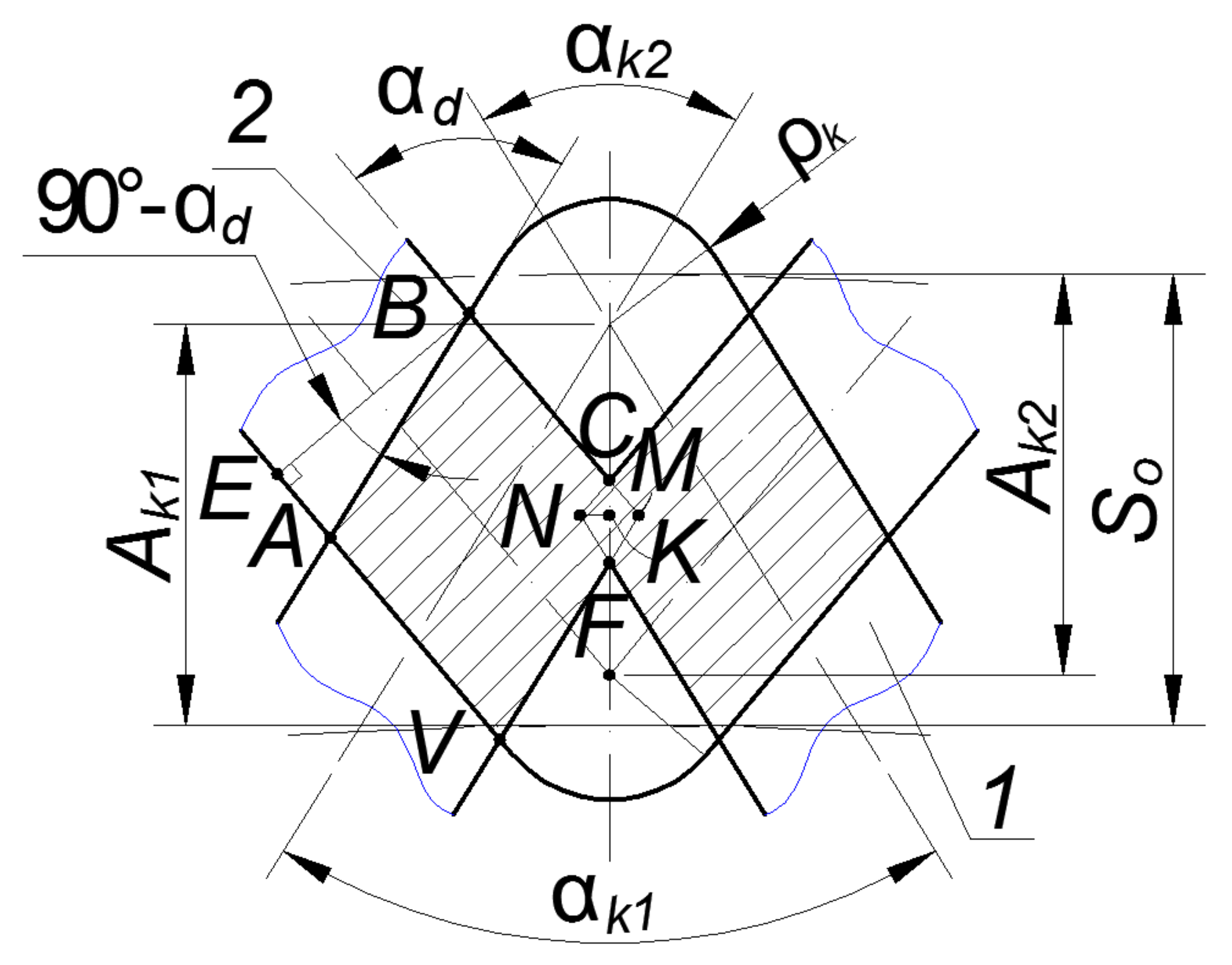
Stage VI. Consider the option when intersecting grooves form two intersecting diamonds (
Figure 8).
The overlap area of grooves 1 and 2 in case of their incomplete intersection was calculated as the sum of diamond areas formed as a result of such intersection (
Figure 7), except for the area of diamond
NCMF, according to the formula:
where
SR is the area of diamond
ABMV, mm
2;
Sr is the area of diamond
NCMF, mm
2.
where
bd is the length of side
AB of diamond
ABMV, mm;
α
d is the central angle
ABC of diamond
ABMV, degrees;
After reductions we obtain:
The area of diamond
NCMF is determined by the formula:
Taking into account Formula (59), Formula (58) takes the following form:
The area of existence for this formula was determined by the limit value of the axial pitch of PRMR, which was determined from the dependence:
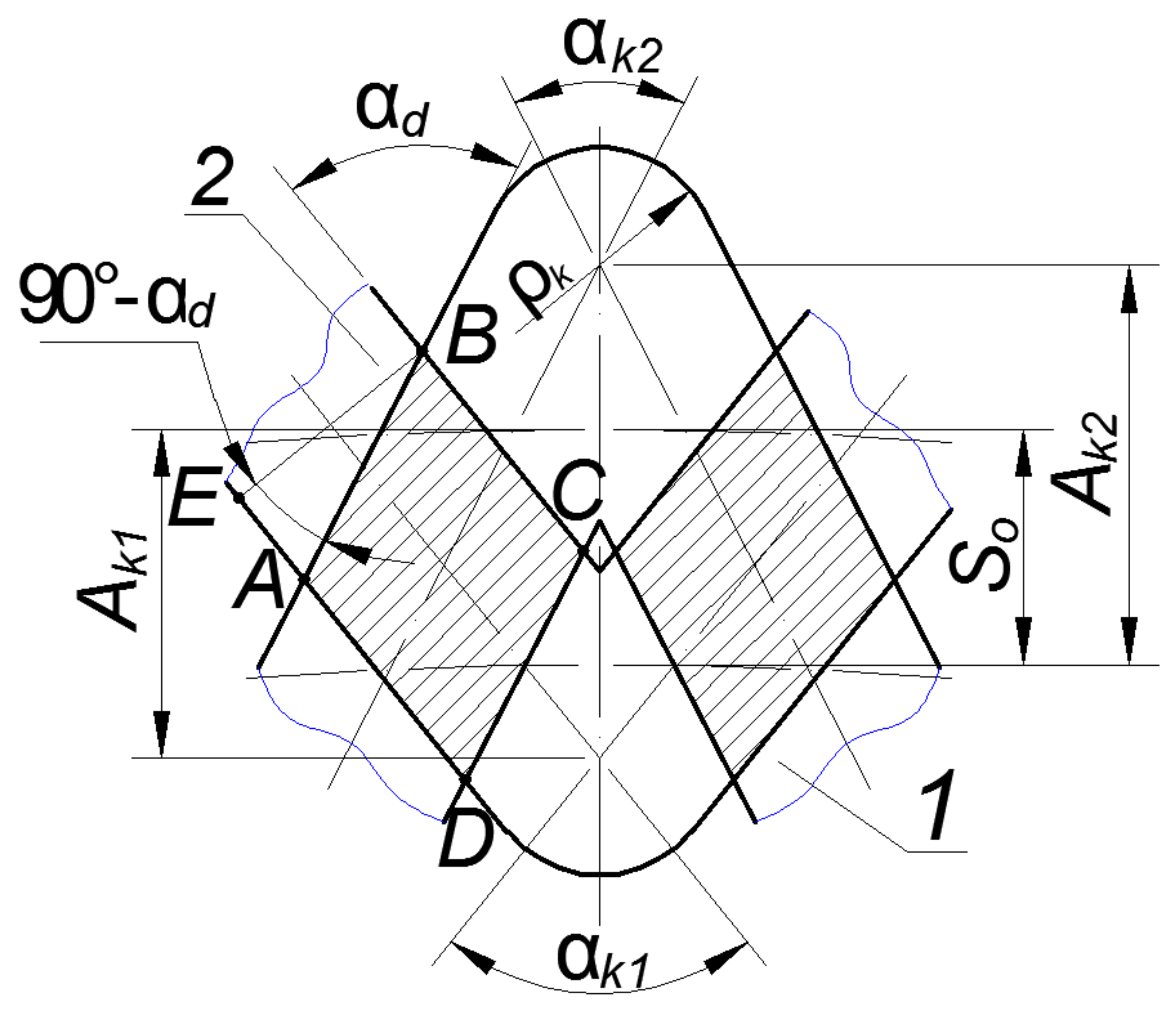
Stage VII. Consider the options when intersecting grooves form two diamonds that do not intersect (
Figure 9).
The overlap area of grooves 1 and 2 in case of their full intersection was calculated as the sum of the diamond areas formed as a result of such intersection (
Figure 7) according to the formula:
where
bd is the length of side
AB of diamond
ABCD, mm; α
d is the central angle
ABC of diamond
ABCD, degrees;
After reductions we obtain:
The area of existence for this formula was determined by the limit value of the axial pitch of PRMR, which was determined from the dependence:
To ensure the same performance properties of the surface with a partially regular microrelief formed on the rotary body end surface, grooves should be placed with such axial pitch, at which the relative vibration area of the microrelief will be the same (
Figure 10).
Having obtained formulas for determining the overlap area of the grooves and their existence conditions, we can develop an algorithm for finding the optimal value of the axial pitch
Soopt (
Figure 11). The optimization criterion will be
Fn (the relative area of burnishing), which should be in the range of 30–45%.
The numbers of formulas by which the corresponding values should be calculated are given in parentheses in
Figure 11.
The following symbols are also used in the block diagram:
Fk is the groove area formed on the rotary body end surface [
30];
Fsur is the end surface area, on which the regular microrelief is formed;
Frm is the groove area formed on a regular microrelief, taking into account the overlap area;
Fn is the relative area of burnishing obtained in [
1].
a is the discrete value of the variation of axial pitch So (which is accepted depending on technical possibilities of the equipment, on which the regular microrelief is formed).
The algorithm for determining the optimal value of the axial pitch So is as follows:
The user enters the initial data (module 2), in particular, the amplitude of oscillations Ak, the number of the groove elements Nel, the radius of RMR elements arrangement Rkc, the imprint radius ρk, the axial pitch So.
The value of variable Soi is assigned to the value of So (the axial pitch of the grooves) (module 3).
The system compares the axial pitch value with the RMR formation condition, on which V-shaped grooves of partially regular microrelief of the 3rd type shifted by an angular pitch of 0.5° (module 4) are formed, namely:
If this condition is not met, the system issues a message that the condition for the formation of RMR of the 3rd type is not met (module 5). If this condition (module 4) is met, the system checks to which of the seven stages of the overlap process belongs the entered value of the axial pitch Soi (modules 6, 8, 10, 12, 14, 16, 18). When one of these conditions is met, the overlap area of the grooves is calculated according to the formulas from the article, the numbering of which is given in parentheses (modules 7, 9, 11, 13, 15, 17, 19).
If none of these conditions is met, the system issues a message about incorrect data (module 20).
After that, the values included in the formula for determining the relative area of burnishing, in particular, Fk, Fsur, Frm (module 21), are determined. Having obtained these values, the system recognizes the value of the relative area of burnishing Fn and checks whether it is greater than the minimum allowable value of 35% (module 22). If not, the system increases the Soi variable by value a (module 23), and the process is repeated from module 3.
If the obtained value of the relative burnishing area Fn is greater than the minimum allowable value, the system checks whether it is less than the maximum allowable value of 45% (module 24).
If the obtained value of Fn is greater than the maximum allowable value, the system reduces the value of Soi by value a (module 25), and the process is repeated from module 3.
If the obtained value of the relative area of burnishing Fn is in the range of 30–45%, the system issues a message that the value of Soi is within optimal limits (module 26).
The intersection of grooves of the partially regular microrelief (type III), which is formed on the end surfaces of rotary bodies, is the most difficult case of their mutual placement, as it has seven different phases. The correctness of determining the relative area of burnishing, which accounts for the performance properties of the formed surface, depends on the correct determination of the intersection area in each of these phases. Therefore, the use of the proposed technique will ensure stable performance properties of the end surface of the rotary body in any part of it.


