Article

Journey Planning Algorithms for Massive Delay-Prone Transit Networks †

1
Department of Information Engineering, Computer Science and Mathematics, University of L’Aquila, Via Vetoio, 67100 L’Aquila, Italy
2
Gran Sasso Science Institute (GSSI), Viale Francesco Crispi, 67100 L’Aquila, Italy
*
Author to whom correspondence should be addressed.
Parts of this paper appeared in extended abstract form within the proceedings of the 19th International Conference on Computational Science and its Applications (ICCSA2019), Saint Petersburg, Russia, 1–4 July 2019.
Algorithms 2020, 13(1), 2; https://doi.org/10.3390/a13010002
Submission received: 29 September 2019 / Revised: 4 December 2019 / Accepted: 10 December 2019 / Published: 18 December 2019

Abstract

:
This paper studies the journey planning problem in the context of transit networks. Given the timetable of a schedule-based transportation system (consisting, e.g., of trains, buses, etc.), the problem seeks journeys optimizing some criteria. Specifically, it seeks to answer natural queries such as, for example, “find a journey starting from a source stop and arriving at a target stop as early as possible”. The fastest approach for answering to these queries, yielding the smallest average query time even on very large networks, is the Public Transit Labeling framework, proposed for the first time in Delling et al., SEA 2015. This method combines three main ingredients: (i) a graph-based representation of the schedule of the transit network; (ii) a labeling of such graph encoding its transitive closure (computed via a time-consuming pre-processing); (iii) an efficient query algorithm exploiting both (i) and (ii) to answer quickly to queries of interest at runtime. Unfortunately, while transit networks’ timetables are inherently dynamic (they are often subject to delays or disruptions), ptl is not natively designed to handle updates in the schedule—even after a single change, precomputed data may become outdated and queries can return incorrect results. This is a major limitation, especially when dealing with massively sized inputs (e.g., metropolitan or continental sized networks), as recomputing the labeling from scratch, after each change, yields unsustainable time overheads that are not compatible with interactive applications. In this work, we introduce a new framework that extends ptl to function in delay-prone transit networks. In particular, we provide a new set of algorithms able to update both the graph and the precomputed labeling whenever a delay affects the network, without performing any recomputation from scratch. We demonstrate the effectiveness of our solution through an extensive experimental evaluation conducted on real-world networks. Our experiments show that: (i) the update time required by the new algorithms is, on average, orders of magnitude smaller than that required by the recomputation from scratch via ptl; (ii) the updated graph and labeling induce both query time performance and space overhead that are equivalent to those that are obtained by the recomputation from scratch via ptl. This suggests that our new solution is an effective approach to handling the journey planning problem in delay-prone transit networks.

1. Introduction

Computing the “best” journeys in schedule-based transit systems (consisting, e.g., of trains, buses, etc.) is a problem that has been faced at least once by everybody who has ever travelled [1]. In particular, the journey planning problem takes as input a timetable (or schedule), that is, the description, in terms of departure and arrival times, of transits of vehicles between stops within the system, and seeks to answer to natural queries such as “What is the best journey from some stop A to some other stop B if I want to depart at time t?”.
Solving (efficiently) such problems constitutes a fundamental primitive in the world of information technologies and intelligent transport systems. Nowadays, in fact, millions of people rely on computer-based journey planning to obtain, accurately and quickly, public transit directions. To this aim, most of the currently deployed journey planners employ algorithms that have been developed and refined in the last couple of decades by researchers in applied algorithmics and algorithm engineering.
In particular, it is known that, despite its simple formulation, the problem is much more challenging than, for instance, the classic route planning problem in road networks [1,2,3], since schedule-based transit systems exhibit an inherent time-dependent component that requires complex modeling assumptions to obtain meaningful results. For this reason, transit companies in the last decade have invested a lot of resources to develop effective systems called journey planners (like, e.g., Google Transit or bahn.de), that store the schedule via a suitable model/data structure and incorporate algorithms to answer efficiently to various types of queries on such model, seeking best journeys with respect to different metrics of interest. Depending on the considered metric and modelling assumptions, the problem can be in turn specialized into a plethora of optimization problems [1].
The most common type of query in this context is the earliest arrival query, which asks for computing a journey that minimizes the total travelling time from a given departure stop to a given arrival stop, if one departs at a certain departure time. Another prominent type of query is the profile query, which instead asks to retrieve a set of journeys from a given departure stop to a given arrival stop if the departure time can lie within a given range. Further types of queries can be obtained by considering multiple optimization criteria simultaneously (multi-criteria queries) or according to the abstraction at which the problem has to be solved. If, for instance, one wants to optimize the transfer time, that is, the time required by a passenger for moving from one vehicle to another one within a stop, then the journey planning problem is called realistic, while it is referred to as ideal otherwise [2]. In this paper, we focus on the realistic scenario, which is much more meaningful from an application viewpoint.

1.1. Related Work

To solve both the ideal and the realistic version of the problems, a great variety of models and algorithms have been proposed in the literature in the last decade, each exhibiting a different performance. In particular, most of them can be broadly classified into two categories: those representing the timetable as an array and those representing it as a graph (see e.g., Reference [1]). Two of the most successful (and effective) examples of the array-based model are the Connection Scan Algorithm (CSA) [4] and the Round-bAsed Public Transit Optimized Router (RAPTOR) [5]. In CSA, all the elementary connections of a timetable are stored in a single array, which is scanned only once per query. An elementary connection represents a vehicle driving from one stop to another without intermediate stops. The acyclic nature of the timetables is then exploited to solve the earliest arrival problem. In RAPTOR, on the other hand, the timetable is stored as a set of arrays of trips and routes, that is suitably defined sets of elementary connections. This representation is used by a dynamic programming algorithm that operates in rounds and extends partial journeys by one trip per round to solve the problem. Several variants of RAPTOR, either incorporating heuristical improvements or considering more refined modeling strategies, have been presented and experimentally analyzed in the last couple of years (see, e.g., References [6,7,8]).
The graph-based models, instead, store the timetable as a suitable graph and execute known adaptations of Dijkstra’s shortest path algorithm to compute optimal routes [2,9,10,11]. Alternatives to both plain array-based and graph-based models have been also recently considered [12,13,14]. Some of them, like the one in Reference [12], directly operate on the timetable. In details, trips are labeled with the stops at which they are boarded and a precomputed list of transfers to other trips is scanned during a query. Newly reached trips are labeled and for a trip reaching a desired destination, a journey is added to the result set. The algorithm terminates only when all optimal journeys have been found.
Some others, like those in References [13,14], combine a graph representation of the timetable with the notion of graph labeling to achieve extremely low query times. In this paper, we focus on this latter category of approaches, since they are the ones that offer the smallest average query times and are hence suited for modern applications of the journey planning problem.

1.2. Motivation

The fastest solutions to the journey planning problem with respect to query time are those in References [13,14]. Of them, the one in Reference [13] relies on an algorithmic framework referred to, in the following, as Public Transit Labeling (PTL). Such a framework employs a heavy preprocessing phase of the input data to speed up the query algorithm at runtime. This allows to obtain query times that have been experimentally observed to be, on average, the smallest among all known techniques, including RAPTOR, CSA and their variants. Such behavior have been observed on all meaningful real-world inputs that have been tested, including continental sized networks and the method has been shown to scale very well with the networks’ size [13].
In more details, ptl consists of three main ingredients: (i) the well-known time-expanded graph model to store transit networks (see e.g., Reference [9]); (ii) a labeling that is a compact representation of the transitive closure of the said graph, computed via a (time-consuming) preprocessing step; (iii) an efficient query algorithm exploiting both the graph and the precomputed labeling to answer quickly to queries of interest at runtime.
On the one hand, the approach outperforms all other solutions in terms of query time and it is general and widely applicable, since several variants of the three mentioned components exist to manage a variety of meaningful application scenarios, including being able to answer to both profile and multi–criteria queries. On the other hand, unfortunately, ptl has the major drawback of not being practical in dynamic scenarios, that is when the network can undergo to unpredictable updates (e.g., due to delays affecting the route traversed by a given vehicle). In particular, even after a single update to the network, queries can return arbitrarily incorrect results, since the preprocessed data can become easily outdated and hence may not reflect properly the transitive closure. Note that recomputing the preprocessed data from scratch, after an update occurs, is not a viable option as it yields unsustainable time overheads, up to tens of hours [13]. Since transit networks are inherently dynamic (delays can be very frequent), the above represents a major limitation of ptl.
Dynamic approaches to update graphs and corresponding (compact) representations of transitive closures have been investigated in the past, in other application domains, due to the effectiveness of such structures for retrieving graph properties [15,16,17,18,19,20,21,22]. However, none of these can be directly employed in the ptl case, where time constraints imposed by the time-expanded graph add a further level of complexity to the involved data structures.

1.3. Contribution of the Paper

In this paper, we move forward toward overcoming the above mentioned limitations, by presenting a new algorithm, named Dynamic Public Transit Labeling (d-ptl, for short), that is able to update the information precomputed by ptl whenever a delay occurs in the transit network, without recomputing it from scratch. It is worthy to mention that, although decreases in departure times are typically not allowed in transit networks [1], hence updating the information in such case would not be necessary, our solution can be easily extended to manage such scenario. It is also worthy to mention that part of the work we present here already appeared in [23].
The algorithm we present here is based on suited combinations of graph update routines inspired to those in Reference [1] and labeling dynamic algorithms, extensions of those in References [15,21,24]. In particular, we present different versions of the algorithm, that are compatible with the different flavors of ptl, namely single criterion and multi-criteria. Furthermore, we discuss on the correctness of d-ptl and analyse its computational complexity in the worst case.
Asymptotically speaking, the proposed solution is not better than the recomputation from scratch. However, we present an extensive algorithm-engineering based experimental study, conducted on real-world networks of large size, that shows that d-ptl always outperforms the from scratch computation in practice. In particular, our results show that (i) d-ptl is able to update both the graph and the labeling structure orders of magnitude faster than the recomputation from scratch via ptl; (ii) this behavior is amplified when networks are massive in size, thus suggesting that d-ptl scales well with the networks’ size. Our data also highlight that the updated graph and labeling structure induce both query time performance and space overhead that are equivalent to those that are obtained by the recomputation from scratch, thus suggesting the use of d-ptl as an effective approach to handle the journey planning problem in delay-prone transit networks.

1.4. Structure of the Paper

The paper is organized as follows. Section 2 gives the basic notation and the definitions used throughout the paper. Section 3 and Section 4 describe the ptl approach [13] in its two flavours, namely single and multi-criteria, respectively. Section 5 and Section 6 present our new dynamic algorithms, in the basic and multi-criteria versions, respectively and discusses correctness and complexity of the new methods. Section 7 presents our experimental study. Finally, Section 8 concludes the paper and outlines possible future research directions.

2. Background

The journey planning problem takes as input a timetable that contains data concerning stops, vehicles (e.g., trains, buses or any means of transportation) connecting stops and departure and arrival times of vehicles at stops. More formally, a timetable T is defined by a triple T = ( Z , S , C ) , where Z is a set of vehicles, S is a set of stops (often in the literature also referred to as stations) and C is a set of elementary connections whose elements are 5-tuples of the form c = ( Z , s i , s j , t d , t a ) . Such a tuple is interpreted as vehicle Z Z leaves departure stop s i S at departure time t d , and the immediately next stop of vehicle Z is stop s j S at time t a (i.e., t a is the arrival time of Z at arrival stop s j S ). Departure and arrival times are integers in { 0 , 1 , , t m a x } representing times in minutes after midnight, where t m a x is the largest time allowed within the timetable (typically t m a x = ( n · 1440 1 ) , where n is the number of days that are represented by the timetable). We assume | C | max { | S | , | Z | } , that is we do not consider vehicles and stops that do not take part to any connection. In the realistic scenario, each stop s i S has an associated minimum transfer time, denoted by mtt i , that is the time, in minutes, required for moving from one vehicle to another inside stop s i .
Definition 1
(Trip). A trip is a sequence TRIP = ( c 1 , c 2 , , c k ) of k connections that: (i) are operated by the same vehicle; (ii) share pairwisely departure and arrival stop, that is, formally, we have c i 1 = ( Z , s i , s j , t d , t a ) and c i = ( Z , s j , s k , t d , t a ) with t d > t d for any i [ 2 , k ] .
Clearly, connections in a trip are ordered in terms of the associated departure times, hence we say connection c j follows connection c j 1 in a trip trip whenever the departure time of the former is larger than that of the latter. Similarly, we say connection c j precedes connection c j + 1 in a trip trip.
Definition 2
(Journey). A journey J = ( c 1 , c 2 , c n ) connecting two stops s i and s j is a sequence of n connections that: (i) can be operated by different vehicles; (ii) allows reaching a given target stop starting from a distinguished source stop at a given departure time τ 0 , that is, the departure stop of c 1 is s i , the arrival stop of c n is s j and the departure time of c 1 is larger than or equal to τ; (iii) is formed by connections that satisfy the time constraints imposed by the timetable, namely that if the vehicle of connection c i is different with reference to that of c i + 1 at a certain stop s h , then the departure time of c i + 1 must be larger than the arrival time of c i plus mtt h .
As well as trips, journeys are implicitly ordered by time according to departure times of the connections. The traveling time of a journey is given by the difference between arrival time of its last connection and τ .
An earliest arrival query ea ( s i , s j , τ ) asks, given a triple s i , s j , τ consisting of a source stop s i , a target stop s j , and a departure time τ 0 , to compute a quickest journey, that is, a journey that starts at any t τ , connects s i to s j , and minimizes traveling time. In what follows we provide two useful definitions that are necessary to introduce the notion of profile query.
Definition 3
(Time-Dominated Journey). Let J and J be two journeys, both connecting two stops s i and s j . Then journey J is time-dominated by journey J if and only if both the following conditions hold:
  • the departure time of the first connection of J is larger than the departure time of the first connection of J ;
  • the arrival time of the last connection in J is smaller than the arrival time of the last connection in J .
By the above, if we let J be the set of all journeys connecting two stops s i and s j in a transit network, then trivially a journey J J is non-time-dominated if and only if either one of the two following conditions hold: (i) the departure time of the first connection of J is larger than the departure time of the first connection of all other journeys in J ; (ii) the arrival time of the last connection of J is smaller than the arrival time of the last connection of all other journeys in J .
Hence, we define a profile query pq ( s i , s j , τ , τ ) as the one that asks for the set of non-time-dominated journeys between stops s i and s j in the time range τ , τ , subject to τ < τ , that is, the set of journeys connecting stops s i and s j that start at any time in [ τ , τ ] and are non-time-dominated journeys.
Finally, we define a multi-criteria query mc-ea ( s i , s j , τ ) as the one asking to compute the set of Pareto-optimal journeys. Informally, such journeys simultaneously optimize more than one criterion (e.g., traveling time and number of vehicle transfers), departing in s i at some time t τ 0 and arriving at stop s j . More precisely, given a set of criteria, a journey is in the Pareto-optimal set S if it is non-dominated by any other journey. A journey J 1 dominates a journey J 2 if it is better with respect to every criterion, while it is non-dominated otherwise. Note that, most commonly considered optimization criteria are traveling time and number of vehicle transfers, although other optimization can be found in the literature, for example, monetary cost.
It is long known that the problem of computing the mentioned Pareto-optimal set is (weakly) NP-hard [25], since such journeys can be exponential in number. However, if some degree of importance of the optimization criteria is imposed then the problem is polynomially solvable, by using a simple multi-criteria modification of the Dijkstra’s algorithm, based on lexicographical optimality [25]. An example of this scenario is when one wants to compute the set of quickest journeys between two stops s i and s j and then, among them, to choose the one minimizing the number of transfers between vehicles. In this paper, we focus on this latter realistic variant of the journey planning problem. As a final remark, observe that profile queries are a special case of multi-criteria ones using arrival and departure times as criteria.

3. Basic Public Transit Labeling

The state-of-the-art method (in terms of query time) to solve the journey planning problem is commonly referred to as Public Transit Labeling (ptl) [13]. The technique comes in two flavors: a basic version to answer to earliest arrival and profile queries only, and an extended, more general version to incorporate generic criteria of optimization, for example, to seek for earliest arrival journeys that also minimize the number of transfers. The basic version essentially consists of three main ingredients:
  • a reduced time-expanded graph, a well-known data structure for storing transit networks (see e.g., Reference [9]);
  • a reachability labeling, a compact labeling-based representation of the transitive closure of the said graph, computed via a (time-consuming) preprocessing step;
  • an efficient query algorithm exploiting both the graph and the labeling to answer quickly to queries of interest at runtime.
In what follows we describe such ingredients in detail.

3.1. Reduced Time-Expanded Graph

The input timetable T = ( Z , S , C ) associated to the transit network is modelled via a reduced time-expanded graph (red-te) [2]. In the case of an aperiodic timetable, the red-te graph is a directed acyclic graph (DAG) G = ( V , A ) [13]. Starting from initially empty sets of vertices V and arcs A, the DAG G associated with the aperiodic timetable T is built as follows. For each elementary connection c = ( Z , s i , s j , t d , t a ) :
  • two vertices are added to V, namely a departure vertex v d c and an arrival vertex v a c , respectively, each having an associated time t i m e ( v d c ) and t i m e ( v a c ) , respectively, such that t i m e ( v d c ) = t d and t i m e ( v a c ) = t a . Departure and arrival vertices are logically stored within the corresponding stop, that is each vertex v d c ( v a c , respectively) belongs to the set of departure (arrival, respectively) vertices DV [ i ] ( AV [ j ] , respectively) of stop s i ( s j , respectively);
  • a directed connection arc ( v d c , v a c ) is added to A, connecting the corresponding departure and arrival vertices.
Furthermore:
  • for each trip TRIP = ( c 0 , c 1 , , c k ) , and for each connection c i TRIP , 0 i < k , a bypass arc ( v a c i , v a c i + 1 ) is added to A, connecting the two arrival vertices of c i and c i + 1 .
  • for each pair of vertices u , v d v [ i ] , a waiting arc (u,v) is added to A if t i m e ( v ) t i m e ( u ) , and there is no w in dv[i] such that t i m e ( v ) t i m e ( w ) t i m e ( u ) .
  • for each u AV [ i ] and for each v DV [ i ] , a transfer arc (u,v) is added to A if t i m e ( v ) t i m e ( u ) + mtt i , and there is no w DV [ i ] such that t i m e ( w ) < t i m e ( v ) and t i m e ( w ) t i m e ( u ) + mtt i .
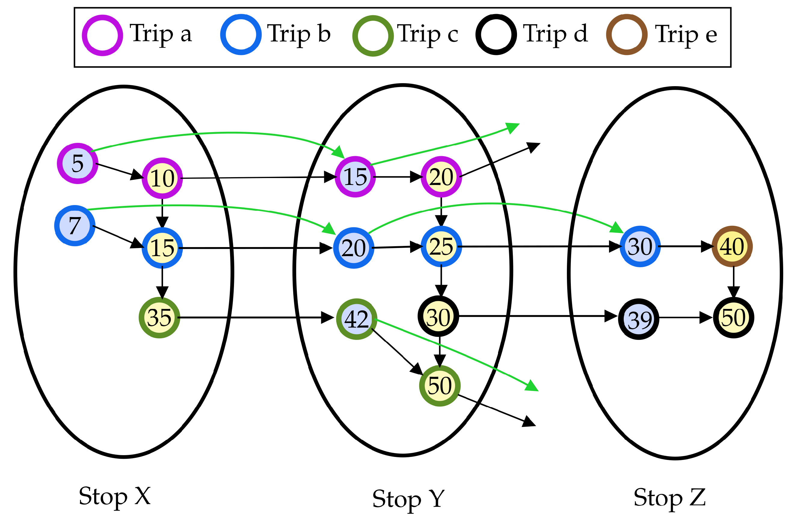
An example of construction of red-te graph is given in Figure 1, built using the timetable of Table 1 as input.
In the remainder of the paper, given a directed graph G = ( V , A ) : we denote by N o u t ( v ) = { u V : ( v , u ) A } ( N i n ( v ) = { u V : ( u , v ) A } , respectively) the set of outgoing (incoming, respectively) neighbors of a vertex v V . We say a vertex u is reachable from (reaches, respectively) another vertex v if and only if there exists a path from v to u (from u to v, respectively) in G, that is, a sequence of arcs ( ( v , v 1 ) , ( v 1 , v 2 ) , , ( v k , u ) ) .
Moreover, we say a path P connecting two vertices u and v is a shortest path between u and v in G if P is a path from u and v in G whose length is minimum among all paths connecting u and v in G. Such length is given by the sum of the weights of the arcs in the path, it is typically denoted by d G ( u , v ) and it is often referred to as the distance from u to v in G.

3.2. Reachability Labeling

Given a graph G = ( V , A ) , any approach for computing a so–called 2-Hop-Cover reachability labeling (2hc-r labeling, for short) l of G associates two labels to each vertex v V , namely a backward label L i n ( v ) and a forward label L o u t ( v ) , where a label is a subset of the vertices of G [26]. In particular, for any two vertices u , v V , L o u t ( u ) L i n ( v ) if and only if there exists a path from u to v in G. Therefore, any query on the reachability between two vertices u , v V can be answered by a linear scan of the two labels of u and v only [26]. Vertices { h : h L o u t ( u ) L i n ( v ) } are called hub vertices for pair u , v , and each element in said set is a vertex lying on a path from u to v in G.
The size of a 2hc-r labeling is given by the sum of the sizes of the label entries and it is known that computing a 2hc-r labeling of minimum size is NP-Hard [26]. However, numerous approaches have been presented to heuristically improve both the time to compute the labeling and its size [24,27,28]. Among them, the one in Reference [24], called butterfly, has been shown to exhibit superior performance for DAGs and is suited for dynamic graphs, that is, the authors also provide a dynamic algorithm that is able to update the 2hc-r labeling l of a graph G to reflect changes occurring on G itself. In particular, given a graph G, a 2hc-r labeling l of G, and an update operation occurring on G, the algorithm is able to compute another labeling L that is a 2hc-r labeling for G , where G is the graph obtained by applying the update on G.
Note that, in this scenario, updates can be incremental (decremental, respectively), if they are additions (removals, respectively) of a vertex/arc. Throughout the paper, we denote by inc-bu (G, l, v) (dec-bu (G, l, v), respectively) the result of the application of the dynamic algorithm of Reference [24] to the labeling l of a graph G to handle an incremental (decremental, respectively) operation occurring on vertex v (we refer the reader to Reference [24] for more details on the above dynamic algorithms).

3.3. Query Algorithm

It has been shown that the above described red-te graph model, combined with 2hc-r labeling, can be used to answer efficiently to both earliest arrival and profile queries on a timetable [13]. In particular, for answering an earliest arrival query of the form ea ( s i , s j , τ ) , the algorithm is as follows. First a vertex c DV [ i ] satisfying the following conditions is computed:
  • t i m e ( c ) τ ;
  • there is no arc (c’,c) adjacent to c such that c DV [ i ] and t i m e ( c ) t i m e ( c ) .
Then, vertices in av[j] are scanned to search for vertices v AV [ j ] such that L o u t ( c ) L i n ( v ) (i.e., that are reachable). If such a vertex v exists, meaning that there exists at least a journey connecting the two stops, then time(v) is returned as the earliest arrival time, only if there is no other v AV [ j ] such that L o u t ( c ) L i n ( v ) and t i m e ( v ) < t i m e ( v ) (this is easy to check as vertices are typically sorted by time). Note that the structure of the journey can be easily retrieved by applying a recursive query procedure [1,13,21].
To answer a profile query pq ( s i , s j , τ , τ ) , instead, the algorithm needs to compute a set of non-dominated journeys, let us call it profile, by proceeding as follows. First, the routine computes a vertex c DV [ i ] such that:
  • t i m e ( c ) τ ;
  • there is no arc (c’,c) adjacent to c such that c DV [ i ] and t i m e ( c ) t i m e ( c ) .
Then, vertices of av[j] are scanned to search for a vertex v AV [ j ] such that:
  • L o u t ( c ) L i n ( v ) (i.e., v is reachable from c);
  • there is no other vertex v AV [ j ] having t i m e ( v ) < t i m e ( v ) and L o u t ( c ) L i n ( v ) .
Note that t i m e ( v ) is the earliest time to arrive at stop s j given the departure time τ from s i . Now, since the set profile must contain all non-dominated journeys, the latest departure time that allows to reach s j is also necessary to complete the computation of the query. To this aim, the algorithm computes another vertex c DV [ i ] such that there is no arc (c″,c‴), with c DV [ i ] , having t i m e ( c ) t i m e ( c ) and L o u t ( c ) L i n ( v ) . The computed time time(c″) is the latest departure time that allows to reach s j . Hence, the algorithm adds pair ( t i m e ( c ) , t i m e ( v ) ) to profile (or alternately the corresponding journey, both versions of the set profile are equivalent [13]), and repeats the process above by setting the value of τ to t i m e ( c ) + 1 .

Stop Labeling

In order to obtain a very fast query time compatible with modern applications, in Reference [13] a customization of the general query approach, tailored for red-te graphs, was proposed. In particular, the main idea underlying the ptl query algorithm is to compact labels and to associate them to stops, rather than to vertices. To this aim, ptl builds a red-te (There is a one-to-one correspondence between red-te graphs and classic time–expanded graphs [2]) graph G, computes a 2hc-r labeling l of G, and compresses it into a set of stop labels sl of l [13]. In detail, we have a forward stop label sl o u t ( i ) and a backward stop label sl i n ( i ) for each stop s i S . A forward (backward, respectively) stop label is a list of pairs of the form ( v , s t o p t i m e i ( v ) ) where v is a hub vertex reachable from (that reaches, respectively) at least one vertex in dv[i] (av[i], respectively) and s t o p t i m e i ( v ) encodes the latest departure (earliest arrival, respectively) time from s i to reach hub vertex v (from the stop, say s v , of vertex v to reach s i , respectively).
For the sake of the efficiency, entries in sl o u t ( i ) (sl i n ( i ) , respectively) are stored as sorted arrays, in increasing order of hub vertices (according to distinct ids assigned to vertices). The set of stop labels is usually referred to as stop labeling of G (or of l). Similarly to the general 2hc-r labeling case, queries on the timetable can be answered via stop labels by scanning the entries associated to source and target stops only. The query algorithms exploit the information in the stop labeling to discard time-dominated journeys toward the stored hubs and to achieve query times of the order of milliseconds [13].
In particular, the routine for answering to an earliest arrival query ea ( s i , s j , τ ) using stop labels is as follows. Since sl o u t ( i ) and sl i n ( j ) are arrays sorted with respect to ids, the algorithm as a first step finds the vertex v in sl o u t ( i ) (sl i n ( j ) whose time is greater than or equal to τ . Assume that said vertex is in position p (q, respectively) in such arrays.
Then, a linear sweep, starting from location p, is performed on sl o u t ( i ) to find the first entry ( v , s t o p t i m e i ( v ) ) satisfying the condition that s t o p t i m e i ( v ) τ . Let us assume this entry is stored in location p p . This part of the computation is known as the process of computing relevant hubs and it is followed by the computation of all hubs that are both sl o u t ( i ) and sl i n ( j ) , stored at locations greater than p and q in sl o u t ( i ) and sl i n ( j ) , respectively. Finally, the earliest arrival time among all such common hubs, computed in the previous step, is returned as an answer to the query ea ( s i , s j , τ ) .
The query algorithm for answering a profile query pq ( s i , s j , τ , τ ) using stop labels works as follows. First, the algorithm performs the computation of relevant hubs, which returns p and q as the locations in sl o u t ( i ) and sl i n ( j ) , respectively. Then, all hubs in both sl o u t ( i ) and sl i n ( j ) , stored at locations greater or equal to p in sl o u t ( i ) , and q in sl i n ( j ) are computed. Finally, among all such common hubs, all non-dominated journeys satisfying the condition that the departure is less than or equal to τ are added to profile, which is initially an empty set. At the end of the procedure, profile is returned as the answer to the profile query pq ( s i , s j , τ , τ ) .

4. Multi-Criteria Public Transit Labeling

The basic ptl approach is not naturally designed for answering to multi-criteria queries, which require a more careful design to achieve lexicographical optimality for generic optimization criteria. However, besides optimizing arrival time, many users also prefer journeys with fewer transfers. To this aim, in Reference [13], the authors show how the basic approach can be modified to handle general multi-criteria queries by modifying its constituents. Briefly, a weighted reduced time-expanded graph (wred-te, for short) is used in place of the red-te graph (again note that there is a one-to-one correspondence between red-te graphs and classic time–expanded graphs [2]), a shortest path labeling replaces the reachability labeling, and the query algorithm is modified accordingly. In what follows, without loss of generality, we describe the modification designed to manage, as optimization criteria, the traveling time and the number of transfers, both to be minimized. However, both ptl and our approach can be extended to handle other criteria (e.g., monetary cost) [13].

4.1. Weighted Reduced Time-expanded Graph

In the specific case, when the additional criterion to be considered is the number of transfers, the weighted reduced time-expanded graph is obtained as follows: each transfer arc ( u , w ) in the graph is assigned a weight of value equal to 1. By interpreting weights of 1 as “leaving a vehicle”, we can count the number of trips taken along any path. To model staying in the vehicle, consecutive connection vertices of the same trip are linked by zero-weight arcs. In such a way, the weight of paths encodes the number of transfers taken during a journey while the duration of the journey itself can still be deduced from the time difference of the vertices. Thus, if one prefers paths in the graph having minimum weight, besides optimizing the time criterion as shown in the previous section, then the sought journey will be the one exhibiting minimum arrival time and minimum number of transfers between vehicles. To this aim, a shortest path labeling [26], instead of a reachability labeling, is employed to accelerate the computation of shortest paths. Notice that, differently from the case of basic ptl, to the best of our knowledge no compact version of the shortest path labeling is known, that is, there is no analog of stop labelings (see Section 3.3) for the multi-criteria setting.

4.2. Shortest Path Labeling

Given a directed graph G, a 2-Hop-Cover shortest path labeling (shortly, 2hc-sp labeling) l of G associates two labels L i n ( v ) and L o u t ( v ) to each vertex v in V, called backward label and forward label, respectively. Differently from reachability labelings, in this case, each label contains additional information, namely each entry in L i n ( v ) ( L o u t ( v ) , respectively) is of the form ( h , δ h v ) ( ( h , δ v h ) , respectively), where:
  • ( h , δ h v ) represents a vertex h in G from which v can be reached via a shortest path of length δ h v ;
  • ( h , δ v h ) represents a vertex h in G reachable from v via a shortest path of length δ v h ;
  • label entries satisfy the so–called cover property that is, for any pair of vertices u , v V , the distance d ( u , v ) (i.e., the weight of the shortest path) from u to v in G can be retrieved by a linear scan of the two labels of u and v only.
In details, a query on the distance is defined as follows:
QUERY ( u , v , L ) = min h V { δ u h + δ h v | ( h , δ u h ) L o u t ( u ) ( h , δ h v ) L i n ( v ) } if   L o u t ( u ) L i n ( v ) otherwise .
It can be shown that, for any 2hc-sp labeling, QUERY ( u , v , L ) always equals d ( u , v ) [26], that is for any two connected vertices u , v V , we have L o u t ( u ) L i n ( v ) and the minimum value of the sums equals the weight of a shortest path in the graph.
In particular, in this case we call hub vertices for pair u , v the vertices in
{ k : k arg min h V { δ u h + δ h v | ( h , δ u h ) L o u t ( u ) ( h , δ h v ) L i n ( v ) } } ,
where each element in said set is a vertex lying on a shortest path from u to v in G. In the above definition we slightly overload our notation by saying that h belongs to L o u t ( v ) ( L i n ( v ) , respectively) whenever ( h , δ v h ) L o u t ( v ) ( ( h , δ h v ) L i n ( v ) , respectively). Note that, despite the same nomenclature, the notion of hub vertex here is more restrictive with respect to reachability labelings, as it requires the vertex to be on a shortest path rather than on any path. To this regard, for 2hc-sp labelings, the following definition can be given. We refer the reader to Reference [29] for more details.
Definition 4
(Induced Path). Given a graph G = ( V , A ) , a pair s , t V and a 2hc-sp labeling L of G, a shortest path P is induced by L for pair s , t V if, for any two vertices u and v in P, there exists a hub h of pair ( u , v ) such that h P , or h = u , or h = v . The set of shortest paths between vertices s and t induced by L is denoted by Path ( s , t , L ) .
Finally, note that, as well as reachability labelings, also for shortest path labelings the size of the labeling is given by the sum of the sizes of the label entries and it is known that computing a 2hc-sp covering of the graph of minimum size is NP-Hard, by a simple reduction to the 2hc-r case [26]. However, numerous approaches have been presented to heuristically improve both the time to compute the labeling and its size [24,27,28].
A reference approach for DAGs (as the wred-te is) is that of Reference [24] which, in the case of shortest path labelings, relies on computing a topological order over the vertices of G. A topological order T on the vertex set V for a DAG is a total ordering defining a precedence relationship among the vertices such that for any arc (u,v) in G we have t ( u ) < t ( v ) , where t ( w ) is the position in the ordering of the generic vertex w V . Note that a topological order can be computed in linear time with respect to the size of the graph. For details about the mentioned approach, we refer the reader to [24] and references therein.
Note also that, for a pair u , v V , the shortest path between u and v in G can be also retrieved from the labeling l by deploying a recursive procedure that builds the path by repeatedly combining hub vertices of pairs of vertices belonging to the path. This is possible due to the optimal sub-structure of shortest paths, where each sub-path of a shortest path is itself a shortest path. We refer the reader to Reference [29] for more details. Such a path between u and v is commonly known as the path induced by the labeling, which in our case is l.

4.3. Multi-Criteria Query Algorithm

It is known that the above described wred-te graph model, combined with a 2hc-sp labeling, can be used to answer efficiently to both earliest arrival and profile queries on a timetable (see Reference [13] for more details). In particular, the routine for answering a multi-criteria query mc-ea ( s i , s j , τ ) is as follows. First, a vertex c DV [ i ] satisfying the following conditions is computed:
  • t i m e ( c ) τ ;
  • there is no arc ( c , c ) in G such that c DV [ i ] and t i m e ( c ) τ , meaning that vertex c is associated with the smallest departure time larger than τ .
Then, the algorithm computes d ( c , v ) , by querying the shortest path labeling l, for all v AV [ j ] such that t i m e ( c ) < t i m e ( v ) , and selects the arrival vertex v having minimum d ( c , v ) . Finally, the time associated to such vertex is the earliest arrival time while d ( c , v ) is the associated number of transfers. Hence, the corresponding journey is the one having the smallest number of transfers among those exhibiting the earliest arrival time: the structure of the journey again can be retrieved by applying a recursive query procedure [13,21]. Note that, to achieve the fastest possible query times, ptl employs some pruning mechanisms [13]. Notice also that, differently from basic ptl, no compact version of shortest path labelings is known, that is there is no analog of stop labelings (see Section 3.3) for multi-criteria queries.

5. Dynamic Public Transit Labeling

In this section, we introduce Dynamic Public Transit Labeling (d-ptl, for short), a new technique that is able to maintain the ptl data structure under delays occurring in the given transit network. In particular, we first show a dynamic algorithm (referred to as basic d-ptl) to update the basic ptl framework, that is how to maintain both a red-te graph G = ( V , A ) , the corresponding 2hc-r labeling l and stop labeling sl under delays affecting connections, and then discuss on how to extend this procedure to the multi-criteria setting.
Formally, a delay is an increase in the departure time of an elementary connection of a finite quantity δ > 0 . Hence, it is easy to see how a delay can induce an arbitrary number of changes to both the graph and labelings [2,13], depending on the structure of the trip the connection belongs to, thus in turn inducing arbitrarily wrong answers to queries.
A general strategy to achieve the purpose of updating both G, the 2hc-r labeling l and the stop labeling sl, after a delay, while preserving the correctness of the queries, is to first update the graph representing the timetable (via, e.g., the solutions in References [2,9,10]) and then reflect all these changes on both l and sl by: (i) detecting and removing obsolete label entries; and (ii) adding new updated label entries induced by the new graph, as done in other works on the subject [21,24]. However, this results in a quite high computational effort, as shown by preliminary experimentation we conducted.
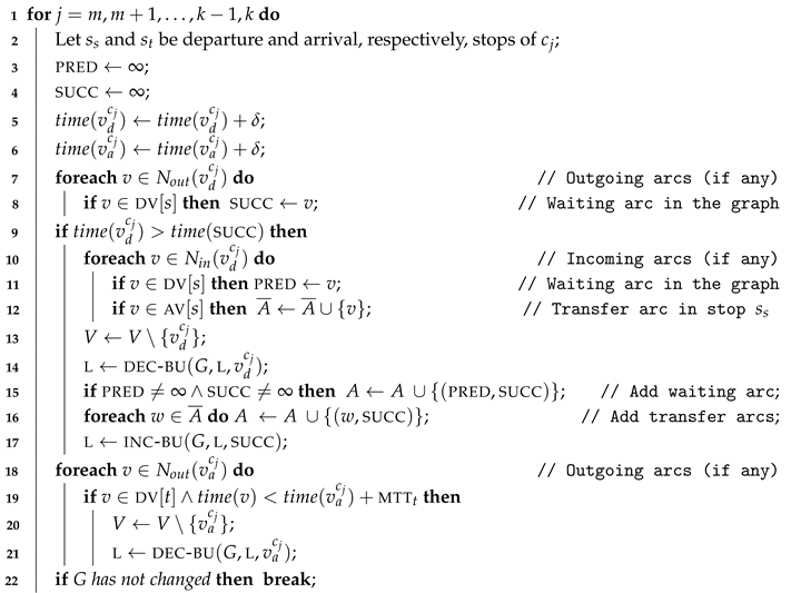
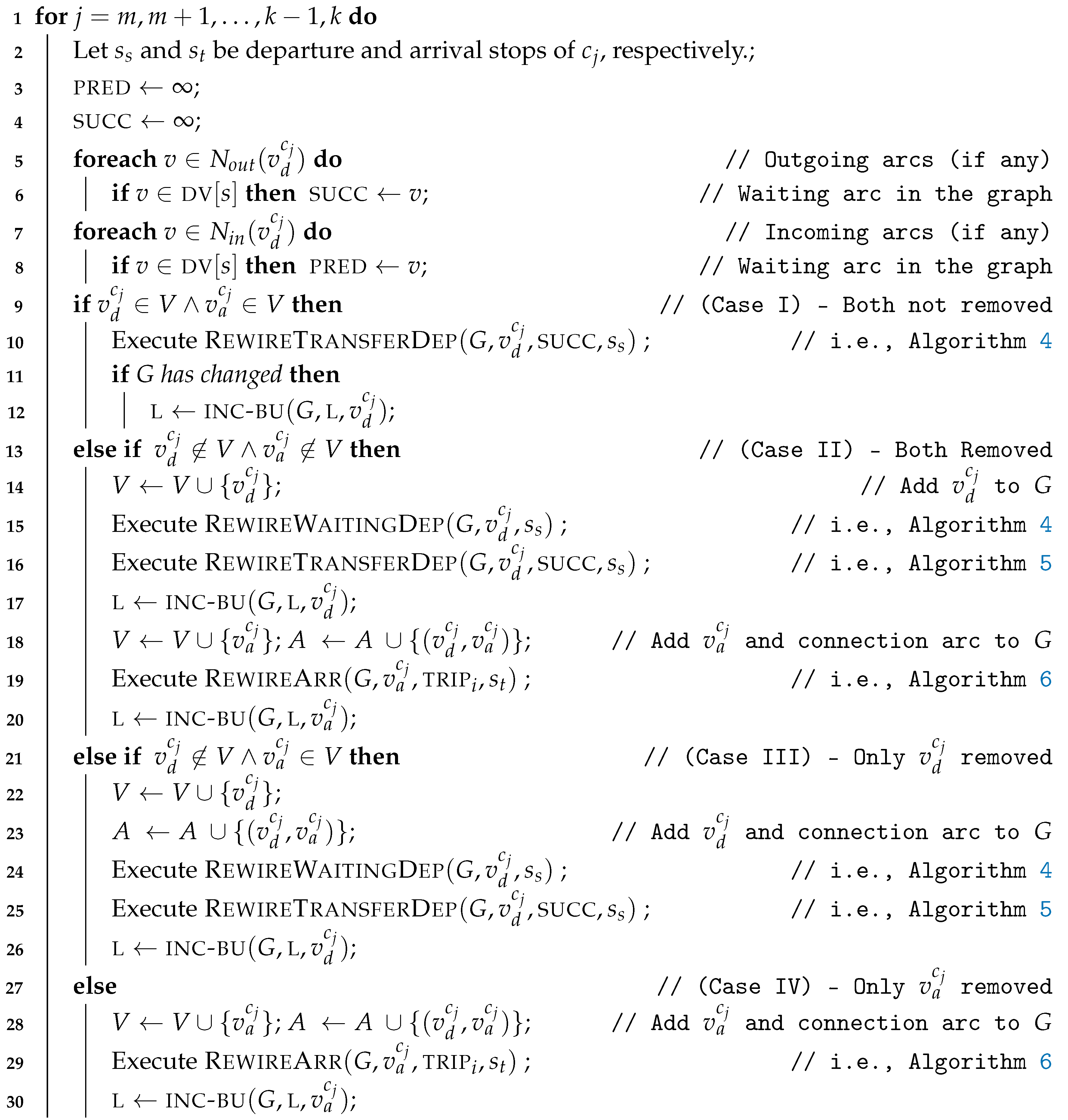
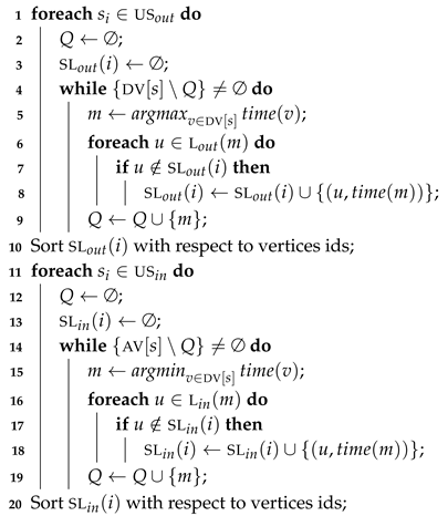
In order to minimize the number of changes to both l and sl, we hence exploit the specific structure of the red-te graph and design a dynamic algorithm that alternates phases of update of the graph with phases of update of the labeling l through the procedures given in Reference [24]. At the end of such phases, changes to l are reflected onto its compact representation sl through a dedicated routine. In particular, our algorithm is based on the following observation: a delay affecting a connection of a trip might be propagated to all subsequent connections in the same trip, if any. Hence, the impact of a given delay on both the graph and the labelings strongly depends on δ , on the structure of the trip and, in particular, on the departure times of subsequent connections. Therefore, d-ptl processes connections of a trip incrementally, and in order with respect to departure time. In details, d-ptl comprises two sub-routines, called, respectively, removal phase (Algorithm rem-d-ptl, see Algorithm 1) and insertion phase (Algorithm ins-d-ptl, see Algorithm 2) that update l along with the graph. Such phases are then followed by a bundle update of sl by a suitable procedure (Algorithm UpdateStopLab, see Algorithm 3).
Algorithm 1: Algorithm rem-d-ptl.
  Input: red-te graph G, a delay δ > 0 affecting a connection c m , the trip TRIP i = ( c 0 , c 1 , , c m , , c k ) including the connection
  Output: red-te graph G not including vertices of connections violating red-te constraints and the 2hc-r labeling l of G
Algorithms 13 00002 i001
Algorithm 2: Algorithm ins-d-ptl.
  Input: red-te graph G not including vertices of connections violating red-te constraints, the 2hc-r labeling l of G, delay δ > 0 , delayed connection c m , trip TRIP i = ( c 0 , c 1 , , c m , , c k )
  Output: red-te graph G including vertices of connections affected by the delay, the 2hc-r labeling l of G, the delay δ > 0 affecting the connection c m and the trip TRIP i = ( c 0 , c 1 , , c m , , c k ) including the connection
Algorithms 13 00002 i002
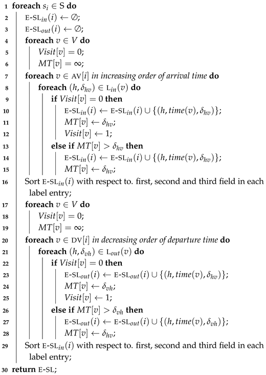
Algorithm 3: Algorithm UpdateStopLab.
  Input: Outdated stop labeling sl, 2hc-r labeling l of G, sets us o u t , us i n
  Output: Updated stop labeling sl of l
Algorithms 13 00002 i003
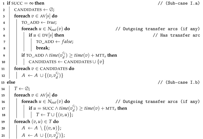
Algorithm 4: Algorithm RewireWaitingDep.
  Input: Graph G = ( V , A ) , departure vertex v d c j , stop s s
Algorithms 13 00002 i004
Algorithm 5: Algorithm RewireTransferDep.
  Input: Graph G = ( V , A ) , departure vertex v d c j , successor vertex succ, stop s s
Algorithms 13 00002 i005
Algorithm 6: Algorithm RewireArr.
  Input: Graph G = ( V , A ) , arrival vertex v a c j , trip trip i , stop s t
Algorithms 13 00002 i006
In the removal phase, we first remove from G vertices and arcs that are associated with the delayed connection that violate the red-te constraints. We say a vertex (arc, respectively) violates the red-te constraints whenever the associated time (the difference of the times of the endpoints, respectively) does not satisfy at least one of the inequalities imposed by the red-te model discussed in Section 2. Note that, vertices and arcs of the above kind can be: (i) departure and arrival vertices of the delayed connection; (ii) departure and arrival vertices following the delayed connection in the same trip; (iii) arcs adjacent to vertices in (i) and (ii).
Once the above is done, we might have that G is no longer a red-te graph, since the removal of the above vertices and arcs can, in turn, induce some other vertex/arc to violate red-te constraints. Hence, we first reflect such removals onto l by running the decremental algorithm dec-bu of Reference [24] and then check if we need to insert into G some new arcs to let it be again a red-te graph. Accordingly, if this is the case, we add label entries induced by these insertions by using the incremental algorithm inc-bu of Reference [24]. At this point, the graph G is a red-te graph of a timetable that does not include the delayed connection. Then, if some changes has been applied to G (and l) in the above step, we proceed by analyzing the connections following the delayed one in the same trip, one by one, and by removing vertices and arcs that violate the red-te graph. At the end of these iterations, we have that G is a red-te graph of a timetable that does not include neither the delayed connection nor those following it in the same trip that have violated the red-te constraints because of δ .
After completing the above, we perform the insertion phase, where we check whether we need to insert back into G some vertices and arcs, with updated associated times, to let the graph be a red-te graph of the updated timetable. This might require to execute algorithm inc-bu to add label entries induced by such insertions. Once both G and l have been updated, we reflect the changes onto the stop labeling via a suited routine (see Algorithm 3). In the next sections we describe in detail the above sub-routines.

5.1. Removal Phase

In the negative case, we do not remove v d c j since, after updating time( v d c j ), all vertices of dv[s] do not violate the time inequalities imposed by waiting arcs. In the affirmative case (see Line 9), instead, v d c j must be removed and the arcs adjacent to vertices in DV [ s ] and AV [ s ] must be rewired. In particular, we proceed as follows: if there exists some waiting arc ( v d c j , v ) in A, that is, there is some other v DV [ s ] whose time was larger than or equal to that of v d c j before the delay), and t i m e ( v d c j ) > t i m e ( v ) (thus the ordering imposed by waiting arcs is violated), then we compute a set A ¯ of vertices that will be wired at v, given by A ¯ = { w : ( w , v d c j ) A : w AV [ s ] } . Note that the time of said vertex v is necessarily larger than the time of vertices w AV [ s ] such that ( w , v d c j ) A plus mtt s , thus satisfy the red-te inequality for transfer arcs.
Moreover, we search for two vertices, named pred and succ respectively, defined as follows:
  • pred is the unique vertex (if any) such that pred DV [ s ] and (pred, v d c j ) A ;
  • succ is the unique vertex (if any) such that succ DV [ s ] and ( v d c j ,succ) A .
These are the vertices adjacent to the waiting arcs having v d c j as one endpoint, that we will need to rewire to preserve the red-te properties. Then, we remove v d c j from V, and run dec-bu to obtain an updated version of the 2hc-r labeling (see Line 14). Note that the removal of a vertex v d c j also removes all arcs (v, v d c j ) and ( v d c j ,v) (if any) from A. Finally, we add: a waiting arc (pred, succ) to A, if both pred and succ are vertices in the graph, and a transfer arc for each entry in A ¯ . In particular, for each vertex w A ¯ , we add a new transfer arc (w, succ). To reflect such changes on l, we run inc-bu (see Line 16).
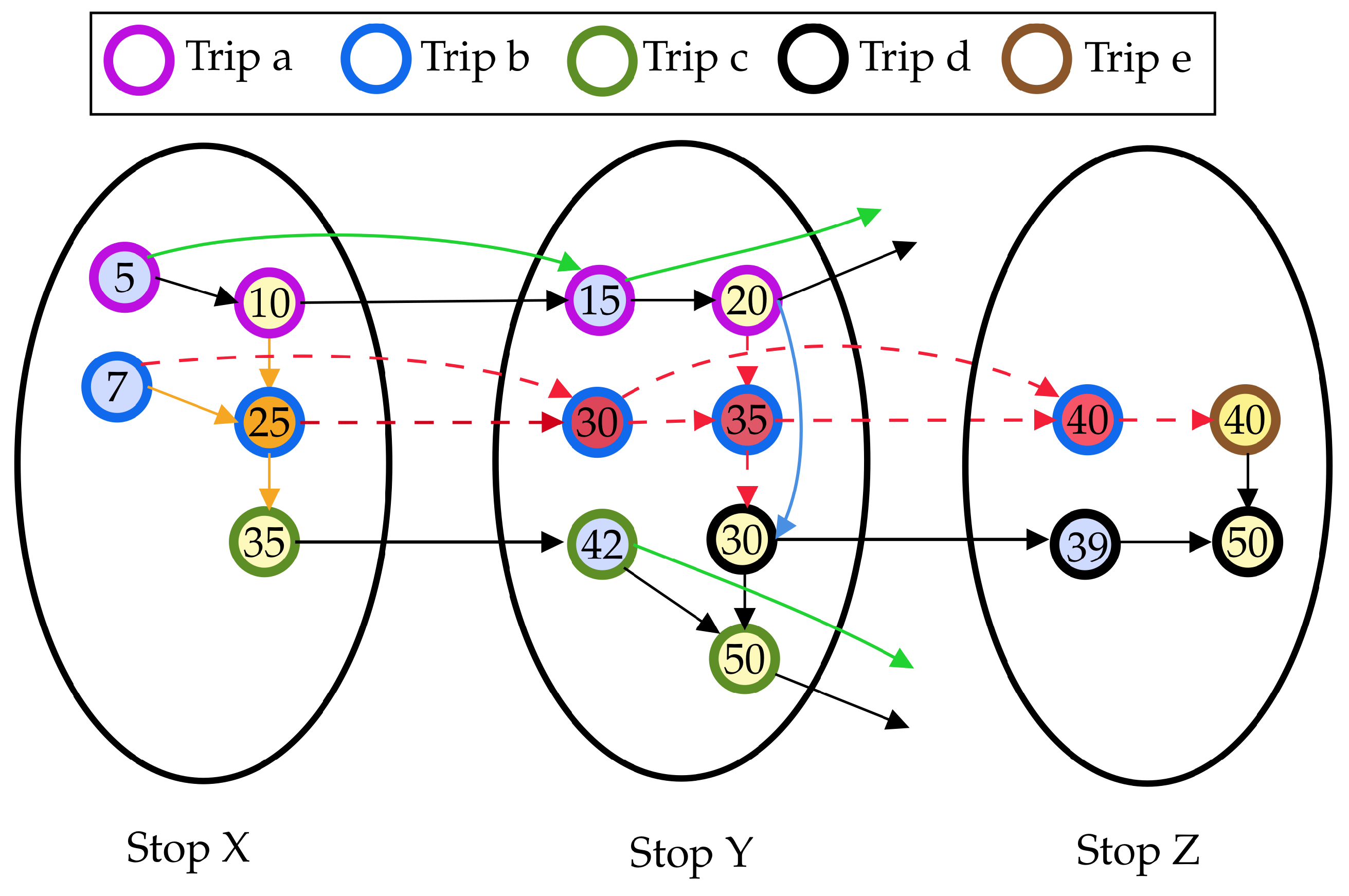
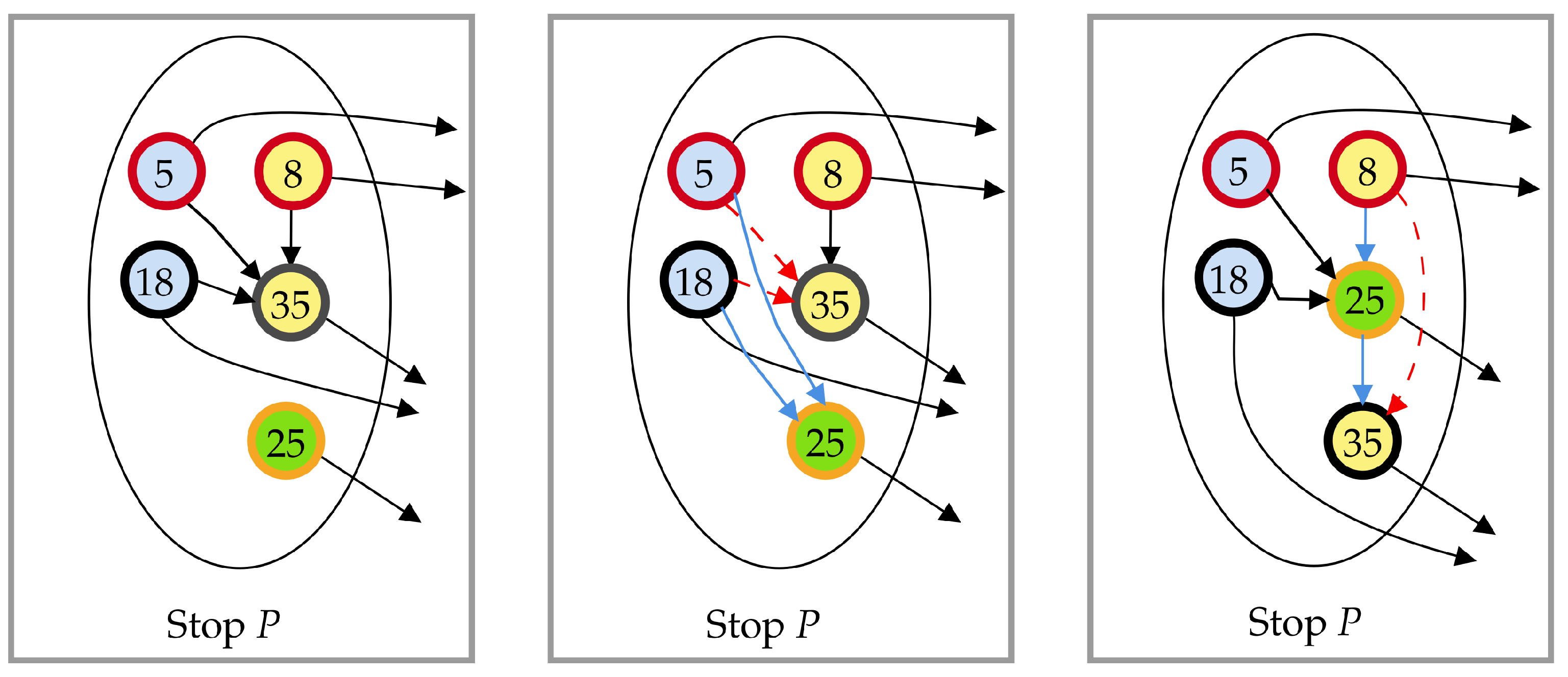
Regarding vertex v a c j , graph G remains unchanged either if there is no transfer arc in A having v a c j as endpoint, or if there is a transfer arc ( v a c j ,v) but such arc is not affected by the delay, that is, when t i m e ( v ) t i m e ( v a c j ) + m t t t . In all other cases, we proceed by removing v a c j from G and by updating l via dec-bu (see Line 21). An example of execution of the removal phase is shown in Figure 2.
As a final remark on this part, notice that (see Figure 2) the removal phase is stopped at a given connection c i of trip TRIP i = ( c 0 , c 1 , , c m , , c i , , c k ) , with m i k whenever the delay does not induce a change neither in the time associated to v a c i and v d c i nor in their adjacent arcs, as this trivially implies that no change will be performed on all vertices v a c j and v d c j (and their adjacent arcs) for all j, with i < j k . This can be detected by comparing the status of vertices (namely time and set of adjacent arcs) before and after performing the procedure for a given connection. In the remainder of the paper, for the sake of brevity, we denote this test by writing either “the graph has changed” or not.

5.2. Insertion Phase

In this section, we discuss in details Algorithm ins-d-ptl whose aim is adding to G vertices and arcs according to the delayed connection in such a way G is a red-te graph properly representing the updated timetable, and then to update accordingly l (see Algorithm 2). In particular, once Algorithm 1 has been executed, the following four cases can occur, for each connection c j , j = m to k in trip TRIP i = ( c 0 , c 1 , , c m , , c k ) that has been affected by the delay, depending on whether the vertices associated have been removed or not from the graph:
(a)
v d c j V and v a c j V ;
(b)
v d c j V and v a c j V ;
(c)
v d c j V and v a c j V ;
(d)
v d c j V and v a c j V .
In what follows we describe in detail how Algorithm ins-d-ptl manage each of these cases.

5.2.1. Discussion on Case I

In this case, when both vertices have remained in G (see Line 9 of Algorithm 2), we only check whether some transfer arcs have to be updated. This process is summarized in Algorithm 5 which is called as sub-routine by Algorithm 2. In particular, if v d c j is the last vertex in dv[s] (see Line 2 of Algorithm 5—Sub-case I.a), i.e., there is no waiting arc outgoing v d c j then we compute the subset candidates of vertices in av[s] that do not have any adjacent transfer arc and would not violate the red-te constraints, i.e., we add a vertex v AV [ s ] to candidates if and only if t i m e ( v d c j ) t i m e ( v ) + mtt s and v does not have any adjacent transfer arc.
Then, for each vertex v CANDIDATES we add a new arc (v, v d c j ) to A.
If, instead, v d c j is not the last vertex in dv[s] (see Line 14 of Algorithm 5—Sub-case I.b), i.e., there exists some waiting arc connecting v d c j to a vertex succ DV [ s ] , then some of the transfer arcs having succ as endpoint in G may need to be updated and connected to v d c j (i.e., rewired to v d c j ). To this purpose, we first determine the subset T A of transfer arcs in A having w as endpoint and then, for each arc ( v , w ) in T A , if t i m e ( v d c j ) t i m e ( v ) + mtt s we replace arc ( v , w ) by a new arc (v, v d c j ). Notice that, for replaced transfer arcs we do not need to update l, since any two vertices that were reachable before such update remain reachable afterward. Moreover, also vertices in dv[s] remain in ordered form, therefore we do not need to add/replace any waiting arc of A. On the contrary, if some modification has been applied to the topology of G or to the ordering of the vertices, then we run inc-bu to obtain an updated version of the 2hc-r labeling (see Line 11).

5.2.2. Discussion on Case II

In this case, occurring when both vertices have been removed from V (see Line 13), we know that the affected connection has no counterpart in G in terms of departure and arrival vertices. Thus, to make G reflect the updated network as a correct red-te model, we proceed as follows.
First, we add a vertex v d c j to V and to dv[s] and set its associated time to be equal to the new departure time of the (delayed) connection. After that, we add arcs adjacent to v d c j , depending on the presence of other vertices in dv[s] and av[s] and on their times. In particular, if t i m e ( v d c j ) t i m e ( v ) v DV [ s ] and DV [ s ] \ { v d c j } , i.e., there is no waiting arc outgoing vertex m = argmax v DV [ s ] t i m e ( v ) and there exists another departure vertex besides v d c j in dv[s], we need to add a waiting arc incoming into v d c j , in particular we insert arc (m, v d c j ) into A.
On the other hand, if there exist some vertices m 1 , m 2 DV [ s ] such that t i m e ( m 1 ) t i m e ( v d c j ) t i m e ( m 2 ) , then we remove waiting arc (m1,m2) and add two new waiting arcs (m1, v d c j ) and ( v d c j ,m2) to A. It is worth to remark here that v d c j cannot be such that t i m e ( v d c j ) < t i m e ( v ) v DV [ s ] since otherwise the original vertex v d c j would have not been removed by Algorithm 1. The pseudo-code of this part of the insertion phase is shown in Algorithm 4 which is again executed as sub-routine of Algorithm 2. Regarding transfer arcs, after v d c j is inserted we execute Algorithm 5, as already discussed for case I. Finally, we run inc-bu to update the 2hc-r labeling l (see Line 17).
Once vertex v d c j has been handled, we focus on the arrival stop s t and insert a vertex v a c j into V and av[t], and a connection arc ( v d c j , v a c j ) to A. Then, to properly set transfer arcs induced by such connection arc, we search for the vertex v in dv[t] such that: (i) t i m e ( v ) t i m e ( v a c j ) + δ and (ii) t i m e ( v ) is minimum among vertices satisfying (i). If such a vertex v exists, then we add arc ( v a c j , v ) to A. Moreover, to properly set bypass arcs, if j 1 we add an arc ( v a c j 1 , v a c j ) , where we remark that v a c j 1 is the arrival vertex of connection c j 1 of trip i . Similarly, j k 1 we add an arc ( v a c j , c j + 1 ) where v a c j + 1 is the arrival vertex of connection c j + 1 of trip i (see Algorithm 6 for the pseudo-code of this phase). Again, we run inc-bu to update l (see Line 20).

5.2.3. Discussion on Case III

In this case, when v d c j has been removed while v a c j is in V (see Line 2 of Algorithm 2), we first add a vertex v d c j to V and to dv[s] and a connection arc ( v d c j , v a c j ) to A. This is followed by the wiring of suited transfer and waiting arcs to v d c j , in order to preserve the red-te properties. As in the previous cases, this is achieved by Algorithms 4 and 5, discussed above. Algorithm inc-bu is also run to reflect changes on the 2hc-r labeling (see Line 26).

5.2.4. Discussion on Case IV

In this case, occurring when v d c j is part of V while v a c j has been removed by the removal phase (see Line 27), we insert a vertex v a c j into V and av[t], and the corresponding connection arc ( v d c j , v a c j ) into A. This is followed by the addition of bypass and transfer arcs adjacent to v a c j , achieved again by Algorithm 6. Furthermore, we obtain the final version l of the 2hc-r labeling (see Line 30).
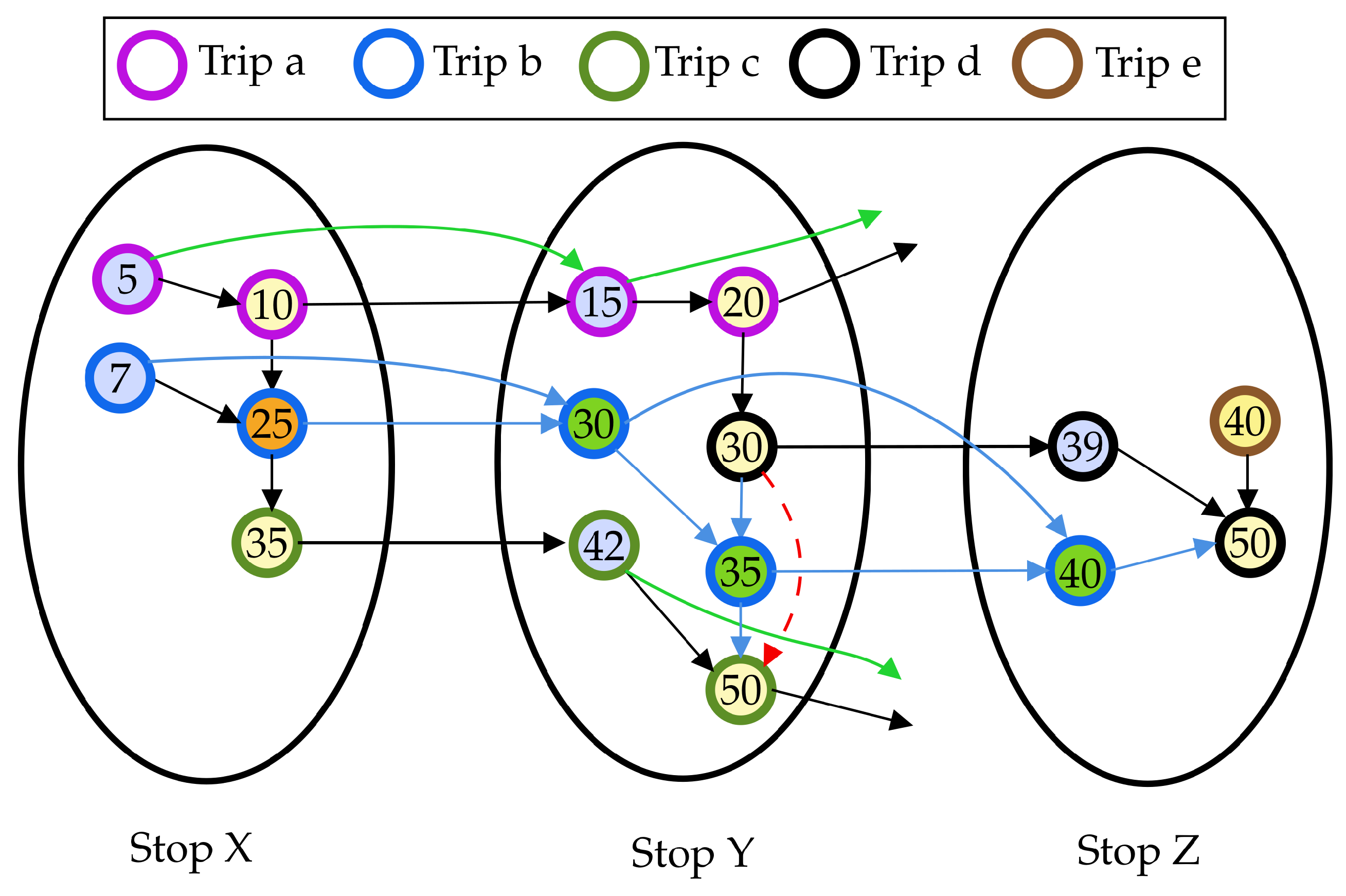
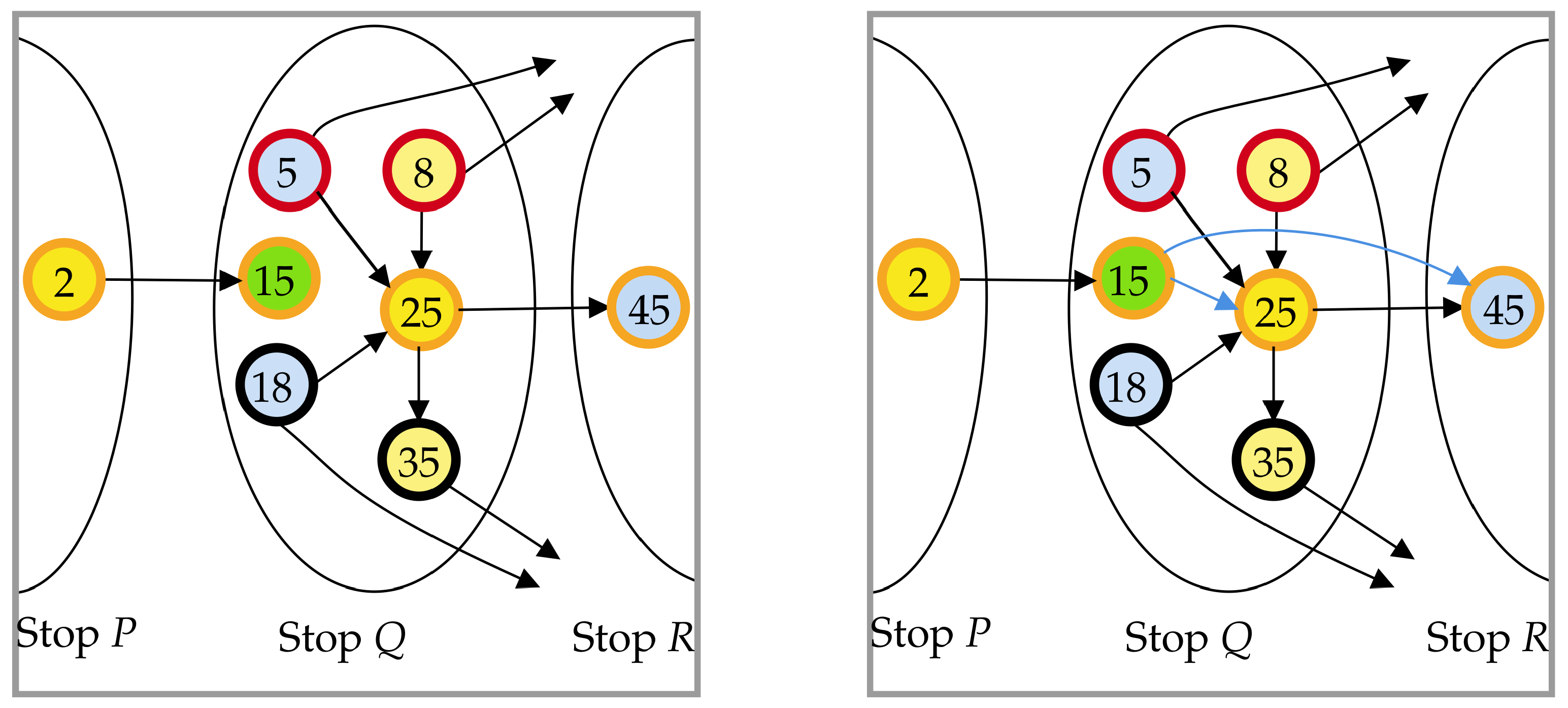
An example of execution of the insertion phase is shown in Figure 3. In addition, for the sake of simplicity in understanding, we show an example of execution of the procedures for: (i) rewiring transfer arcs (Algorithm 5) and waiting arcs (Algorithm 4) to a departure vertex in Figure 4; and (ii) rewiring arcs to an arrival vertex (Algorithm 6) in Figure 5.

5.3. Updating the Stop Labeling

Once both the graph and the 2hc-r labeling have been updated, if a corresponding compressed stop labeling sl is available and one wants to reflect the mentioned updates on said compressed structure, a straightforward way would be that of recomputing the stop labeling from scratch, via for example, the routine in Reference [13]. This computational effort is not large as that required for recomputing the 2hc-r labeling. However, we propose a alternative routine that is incorporated in d-ptl and avoids (and it is faster than) the recomputation from scratch of the stop labeling. Our routine requires, during the execution of Algorithms 1 and 2, to compute two sets of so–called updated stops, denoted, respectively, by us o u t and us i n . These are defined as the stops s i S such that vertices in dv[i] (av[i], respectively) had their time value or forward label (backward label, respectively) changed during Algorithm rem-d-ptl or during Algorithm ins-d-ptl. Sets us o u t and us i n can be easily determined by inserting stops satisfying the property in said sets during the execution of Algorithms 1 and 2, after each update to times or labels.
Once this is done we update the stop labeling sl by recomputing only the entries of sl o u t ( i ) (sl i n ( i ) , respectively) for each s i u s o u t (for each s i u s i n , respectively). To this aim, for each stop s i u s o u t ( s i u s i n , respectively) we first reset sl o u t ( i ) (sl i n ( i ) , respectively) to the emptyset. Then, we scan departure (arrival, respectively) vertices in decreasing (increasing, respectively) order with respect to time and add entries to sl o u t ( i ) (sl i n ( i ) , respectively) accordingly. In particular, for all departure (arrival, respectively) vertices v of s i in the above mentioned order, we add a pair ( u , s t o p t i m e i ( v ) ) for each u in sl o u t ( i ) (sl i n ( i ) , respectively) only if there is no pair sl o u t ( i ) (sl i n ( i ) , respectively) having u as hub vertex. This guarantees that each pair contains latest departure (earliest arrival, respectively) times. After updating the stop labels, we sort both sl o u t ( i ) and sl i n ( i ) to restore the ordering according to the hub vertices [13]. Details on how to update the stop labeling by executing the procedure are given in Algorithm 3.
We are now ready to give the following results.
Theorem 1
(Correctness of Basic d-ptl). Given an input timetable and a corresponding red-te graph G, let l be a 2hc-r labeling of G and let s L be a stop labeling associated to l. Assume δ > 0 is a delay occurring on a connection, that is, an increase of δ on its departure time. Let G , L , and SL be the output of d-ptl when applied to G, l and s L , respectively, by considering the delay. Then: (i) G is a red-te graph for the updated timetable; (ii) L is a 2hc-r labeling for G ; (iii) s L is a stop labeling for L .
Notice that, the above theorem is based on the correctness of the approaches in References [2,13,24]. In particular, it is easy to see that whenever we update the graph, we do it by preserving the constraints imposed by the red-te model on both vertices, by suitably modifying connection arcs and associated waiting, bypass, and transfer arcs. In more details, it is easy to prove, by contradiction, that after the execution of Algorithms 1 and 2, G is a red-te graph. Concerning the labeling data structures, observe that after each change to G we use either dec-bu or inc-bu, depending on the type of performed modification. These algorithms have been shown to compute a labeling that is a 2hc-r labeling for the modified graph [24]. Hence, at the end of Algorithm 2, l is a 2hc-r labeling for G. Finally, Algorithm 3 applies the definition of stop labeling, by updating the entry of a stop with the proper hub vertices and times values. Hence, after the execution of Algorithm 3, sl is a stop labeling of l and the theorem follows.
Theorem 2
(Complexity of Basic d-ptl). Algorithm d-ptl takes O ( | C | 3 log | C | ) computational time in the worst case.
Proof. 
The complexity of Algorithm d-ptl is given by the sum of the complexities of Algorithms 1, 2 and 3. In what follows, we analyze separately the three algorithms.
Concerning Algorithm 1, we first bound the cost of executing Lines 1–21, that is, the amount of computational time per connection. Lines 1–8 require a time that is linear in the number of neighbors (incoming and outgoing) of v d c j , which is a constant in red-te graphs, while lines 9–21 spend a time that grows as said number of neighbors times the time required for performing the dynamic algorithms dec-bu and inc-bu. Each execution of these algorithms takes O ( | V | 2 log | V | ) in the worst case [24]. Thus, lines 1–21 require O ( | V | 2 log | V | ) time in the worst case. These lines are repeated for all stops traversed by the vehicle of the trip from connection c m to c k , therefore in the worst case for all stops of the transit network, which are | S | | C | . Since | V | O ( | C | ) , we have that Algorithm rem-d-ptl runs in O ( | C | 3 log | C | ) worst case time.
Concerning Algorithm 2, notice that all sub-routines require a time that is linear in the size of the processed stop (i.e., in the number of associated arcs). Hence, by summing up the contribution for all considered stops (those traversed by the trip from connection c m to c k ), we obtain that updating the graph via Algorithm ins-d-ptl takes O ( | C | ) , as | C | max { | S | , | Z | } and, in the worst case, the affected trip can traverse all stops of the network. On top of that, we need again to consider the time for executing dec-bu and inc-bu, which are performed again | S | | C | times in the worst case. Since | V | O ( | C | ) , we have that Algorithm ins-d-ptl runs in O ( | C | 3 log | C | ) worst case time.
Concerning Algorithm 3, it scans label entries of vertices in both us i n and us o u t in non–increasing and non–decreasing order, respectively (thus requiring either to sort them or to use a priority queue). In both cases, we have an additional logarithmic factor in terms of computational time per vertex. Since all vertices for all stops can be O ( | C | ) , and since sorting stop labels with respect to hub vertices at the end of the procedure requires O ( | C | log | C | ) worst-case time, it follows that the worst case time of Algorithm 3 is O ( | C | log | C | ) . If we sum up the complexities of Algorithms 1, 2 and 3, the claim follows.  □
Notice that, Theorem 2 implies that d-ptl, in the worst case, is slower than the reprocessing from scratch via ptl, whose worst case running time is cubic in the size of the graph due to the recomputation of the labeling [20].
However, our experimental study, which is described in Section 7, clearly shows that d-ptl always outperforms ptl in practice.

6. Dynamic Multi-Criteria Public Transit Labeling

In this section, we extend d-ptl to handle the multi-criteria setting. We refer to the extended version as multi-criteria d-ptl.
We remark that, to update the data structures employed by the basic ptl framework, d-ptl exploits the structure of the red-te graph and alternates phases of modifications of the graph itself with corresponding updates of the reachability labeling via the procedures given in [24]. These phases are bundled in two blocks, namely the removal phase (Algorithm rem-d-ptl, see Algorithm 1) and insertion phase (Algorithm ins-d-ptl, see Algorithm 2) that update the labeling along with the graph.
The above two routines, however, cannot be directly employed within the multi-criteria ptl approach, that relies on a shortest path labeling rather than on a reachability one. In particular, while the modifications to the graph applied by the two routines are almost same for wred-te graphs (the only exception is that whenever we add a transfer arc we need also to add a suited intermediate vertex for modeling a transfer, whenever the two vertices are associated to connections of different trips.), we cannot use algorithm butterfly, which is designed for reachability labelings, to update the shortest path labeling at hand. Hence, we need to replace dec-bu (in lines 14 and 21 of Algorithm 1) and inc-bu (in lines 11, 17, 20, 26, and 30 of Algorithm 2) with decremental and incremental algorithms that are suited to update the 2hc-sp labeling. To this regard, we can employ the decremental algorithm decpll of Reference [21] and the incremental algorithm incpll of Reference [15], respectively, that are designed to update 2hc-sp in general graphs.
Unfortunately, by preliminary experiments we conducted on some relevant instances of the problem (we recall the reader that graphs treated in this paper are specifically DAGs), we observed that, while incpll is quite fast and updates the labeling within few seconds even in very large graphs, decpll is painfully slow, and sometimes its computational time is comparable with that required for recomputing the labeling from scratch. This is most likely due to the sparse nature of the red-te graph and to how decpll updates 2hc-sp labelings. In more details, decpll works in three phases whose running time depends proportionally on the cardinality of the set of vertices that contain at least a label entry that is incorrect. It is easy to see that this cardinality tends to the number of vertices of the graph in DAGs in most of the cases (see Reference [21] for more details on this part of the computation).
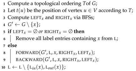
For such reasons, in what follows we propose an extension of algorithm dec-bu, named dag-decpll, that is explicitly designed to update shortest path labelings in DAGs, instead of reachability labelings, as a consequence of decremental updates to the graph. The main intuition behind dag-decpll is to exploit the specific relationships between shortest paths in DAGs, which are instead neglected by decpll, which is designed for general graphs.
Given a graph G = ( V , A ) , we discuss the new approach by focusing on how to handle the removal of a vertex, say x V , which is the decremental operation of interest in our scenario. Note that, the routine can be easily extended to handle arc removals or arc weight increases, as discussed at the end of this section. In what follows, we call G = ( V , A ) the graph obtained by removing vertex x from V. Furthermore, we denote by d S ( u , v ) the distance (i.e., the weight of a shortest path) between two vertices u and v of a graph, say S. and define two subsets of vertices of V, namely right x and left x , as follows:
  • right x : the set of vertices of V that are reachable from x in G, i.e.,  u right x if and only if there exists a path from x to u in G;
  • left x : the set of vertices of V that can reach x in G, i.e.,  u left x if and only if there exists a path from u to x in G.
Since G is a DAG, it is easy to see that right x and left x are inherently disjoint, that is right x left x = . Additionally, given the above definitions, we say a label entry ( h , δ v h ) l o u t ( v ) of some vertex v V is affected by the removal of a vertex x V only if x lies on a shortest path between v and h induced by l. Similarly, a label entry ( h , δ h v ) l i n ( v ) is affected by the removal of a vertex x V only if x lies on a shortest path between h and v induced by l.
In what follows, given a vertex x V , we highlight some simple yet important properties of the two sets right x and left x that are easily derived by the structure of DAGs.
Property 1.
For any vertex v V such that v right x { x } no label entry inl i n ( v ) is affected by the removal of x from G.
Corollary 1.
For any vertex v right x , a label entry ( h , δ h v ) inl i n ( v ) may be affected only if h left x or if v = x .
Property 2.
For any vertex v V such that v left x { x } no label entry inl o u t ( v ) is affected by the removal of x from G.
Corollary 2.
For any vertex v left x , a label entry ( h , δ v h ) inl o u t ( v ) may be affected only if h right x or if v = x .
Lemma 3.
For any pair of vertices u , v in V, if u left x and  v right x , then QUERY ( u , v , L ) = d G ( u , v ) . Symmetrically, if v right x and  u left x then QUERY ( v , u , L ) = d G ( v , u ) .
Proof. 
The above easily follows by Properties 1 and 2. Notice that, when h left x { x } ( h right x { x } , respectively), the shortest path from h to v (from v to h, respectively) cannot pass through x by the definition of left x (right x , respectively).  □
According to the previous observations, we now provide a strategy to carefully identify the label entries that are affected by the removal of a vertex x from G. In particular, for each vertex v right x ( v left x , respectively) we know that l i n ( v ) (l o u t ( v ) , respectively) can contain affected label entries, which must be either removed or updated in order to preserve the correctness of the query algorithm. The routine to achieve the update is based on the notion of marking label entries, that is we assume to store an additional boolean field, attached to each label entry, encoding the information “the label entry is marked or not”. We assume initially all these bits are set to false.
Given the additional boolean field, we define a so–called marked query between two vertices u and v, denoted as mquery ( u , v , L ) , that behaves as a regular query on the labeling with the difference that it considers only those label entries that are either marked or such that their associated vertices do not belong to either left x or right x . This is done with the purpose of distinguishing label entries that have already been updated with the correct distance or such that the attached distance is not changed by the removal of x. We will show later in the section how this modified query is used to retrieve correct distances during the update.
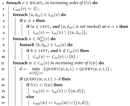
Algorithm dag-decpll, whose pseudocode is given in Algorithm 7, exploits the above properties and definitions and works as follows. Given the vertex x, the algorithm first computes a topological order T of the graph in linear time. Then, sets right x and left x are determined, again in linear time via a forward and backward, respectively, execution of the well known breadth-first search (BFS, for short) algorithm, starting from x. This is followed by the removal of x from G. Now, if either right x or left x are empty, the algorithm simply removes all entries that have x as first field in the labeling l, by linearly scanning it, and terminates. Note that, it is very unlikely for right x or left x to be empty, therefore the removal of x from l is done in the trivial way, rather than employing explicitly some data structure storing an inverted index for each label entry in l. Otherwise, the algorithm proceeds in two phases, called forward update and backward update, that scan vertices that can contain obsolete label entries (namely vertices in left x and right x , respectively) with the purpose of either removing them or updating the associated distances. The two phases are described in details separately in the following sections. At the end of the two, dag-decpll removes l o u t ( x ) and l i n ( x ) from l and returns the updated label set. In the pseudocode, we denote by N o u t G ( v ) ( N i n G ( v ) , respectively) the out-neighbors (in-neighbors, respectively) of the generic vertex v of graph G.
Algorithm 7: Algorithm dag-decpll.
  Input: Directed Acyclic Graph G, 2hc-sp labeling l of G, vertex x to be removed from G
  Output: Directed Acyclic Graph G = G \ { x } , 2hc-sp labeling l of G \ { x }
Algorithms 13 00002 i007

6.1. Forward Update

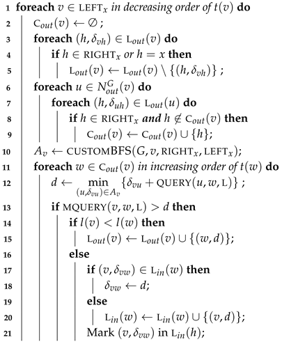
The procedure processes vertices in left x in decreasing order with respect to a topological ordering T of G. Assume we are processing a given vertex, say v. If v has a maximum value in T as compared to that for the rest of vertices in left x , then we know by the definition of T that no vertex in N o u t G ( v ) belongs to left x . We also know that a label entry ( h , δ v h ) l o u t ( v ) may be affected if h = x and  h right x (see Corollary 1). Moreover, it can be easily seen that, for any vertex u N o u t G ( v ) with u left x , no label entry in l o u t ( u ) is affected by the removal of x from G (see Corollary 2). Additionally, for the rest of cases where u N o u t G ( v ) and  u left x , by definition of T, u must have been processed before v.
The routine hence proceeds by removing all affected label entries from l o u t ( v ) . Notice that, after removing such label entries, we can retrieve the correct distance in the new graph d G ( v , w ) for any vertex w V such that w right x , by performing a query query ( v , w , L ) , since the path induced by the labeling does not contain x in these cases. However, to guarantee that the cover property of l is satisfied with respect to all pairs of vertices of the new graph G , we may need to add new label entries to l o u t ( v ) and possibly to backward label sets of vertices in right x . To this aim, we exploit the notion of superset of hubs, originally presented in Reference [24], and incorporate it in the dag-decpll update procedure after suitably adapting it in order to make it compatible with 2hc-sp labeling.
In more details, the superset of hubs for a forward label l o u t ( v ) , denoted by C o u t ( v ) , is defined as the union of the hub vertices, belonging to right x , in all forward label sets of all vertices in N o u t G ( v ) . More formally:
C o u t ( v ) = u N o u t G ( v ) { k | ( k , δ u k ) L o u t ( u ) h RIGHT x } .
In the case of reachability labeling one can exploit the notion of superset of hubs to update the reachability properties of a given vertex v: if a neighbor of v is reachable from a given vertex, so is v. Here, instead, we exploit it to simplify the update of the distances stored in the label entries. In details, since we are updating a 2hc-sp labeling, to achieve the update of the label of a given vertex v, we need to compute d G ( v , h ) for all h C o u t ( v ) and use it to update entries δ v h l o u t ( v ) so that they correspond to distances in the new graph.
One way to do this is to execute a baseline algorithm for computing shortest paths in DAGs. However, even if it is well known that this costs linear time with respect to the graph size, this can easily become a computational bottleneck when dealing with medium to large scale graphs, since we need to compute many distances during an update.
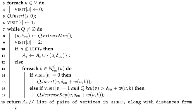
To overcome this limit, we propose a hybrid approach that exploits G and l to compute distances faster. In more details, it is easy to observe that for any h C o u t ( v ) and for any w V such that w left x , the correct distance d G ( w , h ) can be computed via a query on the labeling query ( w , h , L ) , since the path induced by the labeling from w to h cannot include x (see Lemma 3). Moreover, for any h C o u t ( v ) the path between v and h must pass through at least a vertex in right x . This implies that, if we have the set of vertices S = { v V | v left x u N i n G ( u ) : u left x }, that are reachable from v in G , then d G ( v , h ) is given by the minimum value between δ v u + QUERY ( u , h , L ) among all vertices u S (note that δ v u can be retrieved from l). Therefore, to compute d G ( v , h ) for all h C o u t ( v ) , we run a pruned BFS starting from v (see sub-routine shown in Algorithm 8).
Algorithm 8: Algorithm customBFS.
  Input: Directed acyclic graph G, a vertex s of G, sets right x and left x
  Output: Set of pairs of vertices and relative distances from s
1 Q
2 A s
Algorithms 13 00002 i008
Once all distances are available, we process the vertices in C o u t ( v ) in increasing order with respect to topological sorting. In particular, for each w C o u t ( v ) in increasing order of t ( w ) , we update the label entries by using the computed distances, the notion of superset, and the labeling l (see Lines 11–21 of Algorithm 9). Whenever we add a new label entry or update an existing one, we mark the entry so that we keep trace of distances that have already been checked. On top of that, after the first iteration, we exploit the marked query every time we need to check whether a discovered distance d, passing through a vertex, is already encoded in the labeling or not. Finally, notice that, whenever we add a new label entry to the 2hc-sp labeling, we insert it in order to preserve the well-ordered property [26]. This property guarantees that the labeling is minimal in size (i.e., if a single entry is removed, the cover property is broken). To achieve it, vertices are sorted according to any reasonable criterion before the initial preprocessing takes place and, whenever a label entry associated with an hub h has to be added to the label set of a vertex v, this is done if and only if h preceedes v in the established order (we refer the reader to Reference [21,26] for more details). We denote by l ( v ) the position of a vertex v V according to the established order.
Algorithm 9: Procedure forward.
  Input: Directed Acyclic Graph G, 2hc-sp labeling l of G, vertex x to be removed from G, sets right x and left x
Algorithms 13 00002 i009

6.2. Backward Update

The procedure processes vertices in right x in increasing order with respect to the same topological ordering T of G. Assume we are processing a given vertex, say v. We know that a label entry ( h , δ v h ) l i n ( v ) is affected if h = x and  h left x (see Lemma 3). However, in this case, there may be marked label entries, for example,  ( h , δ v h ) l i n ( v ) such that h left x , that have been added in the forward update phase and that are therefore not considered as affected (they have already been updated). Moreover, it can be easily seen that, for any vertex u N i n G ( v ) with u right x , no label entry in l i n ( u ) is affected by the removal of x from G (see again Lemma 3). Additionally, for the rest of cases where u N i n G ( v ) and  u right x , by definition of T, u must have been processed before v. Hence, we proceed by removing all affected entries from l i n ( v ) , where a label entry ( h , δ h v ) l i n ( v ) now is affected only if h = x or h left x and  ( h , δ h v ) is not marked.
Notice that, after removing affected label entries from l i n ( v ) , we can compute correct values of d G ( w , v ) for any w V such that w left x , via a query query ( w , v , L ) . However, to restore the cover property for other vertices, we may need to add new label entries to l i n ( v ) and possibly to forward label sets of some of the vertices in left x . To this end, symmetrically to the forward update case, we compute the superset of hubs, this time for the backward label l i n ( v ) , denoted as  C i n ( v ) , as the union of the hub vertices, belonging to left x , for all backward label sets of all vertices in N i n G ( v ) , that is:
C i n ( v ) = u N i n G ( v ) { k | ( k , δ k u ) L i n ( u ) h LEFT x } .
Observe that, for any w C i n ( v ) , the path between w and v in G must pass through one of the vertex in N i n G ( v ) , by the structure of the DAG G. Moreover, we also know that for any w V and for any u N i n G ( v ) , the distance d G ( w , u ) can be correctly computed via a query query ( w , v , L ) . In particular, it is given by the minimum value we obtain for QUERY ( w , u , L ) + QUERY ( u , v , L ) among all vertices u N i n G ( v ) . If this value is not encoded in the labeling, we add ( u , δ u v ) to l i n ( v ) if l ( v ) > l ( u ) , otherwise we add ( v , δ u v ) to l o u t ( u ) .
We are now ready to discuss on the correcntess of the newly proposed approach.
Theorem 4
(Correctness of dag-decpll). Let G be a DAG, let l be a 2hc-splabeling of G, and let x be a vertex of G. Let G = G \ { x } and  L be the output of algorithm dag-decpll when applied to G, l and x. Then: a) G = G \ { x } is a DAG and b) L is a 2hc-sp labeling of G .
Proof. 
Concerning (a), the proof is trivial. In fact, if the topological ordering property is true on the arcs of G, then it will hold on G , as we only remove a vertex and its adjacent edges. Regarding (b), we need to show that the cover property holds for all pairs of vertices of the new graph. To this end, first observe that we remove all label entries that induce paths that include the removed vertex x. Then, notice that, in both forward and backward procedures, we test the property for all and only the vertices that are affected by the removal of x (sets right x and left x ) and that the algorithm adds new label entries to vertices by considering them in the order imposed by the topological sorting. The addition of new label entries is done incrementally, by either relying on distances that are: (i) either computed in the new graph via the customBFS; or (ii) obtained by combining distances encoded in the labeling that have surely not changed because of the removal of x; or (iii) marked, and hence already updated by previous iterations of the two procedures.  □
Theorem 5
(Complexity of dag-decpll). Algorithm dag-decpll takes O ( | V | 3 ) in the worst case.
Proof. 
Note that, for each vertex in left x , the algorithm: (i) scans the neighbors and analyzes the label sets of such neighbors (possibly removing some entries); (ii) executes procedure customBFS; (iii) processes vertices in C o u t ( v ) and for each one of them possibly performs a marked query. Concerning (i), asymptotically this costs overall quadratic time in the size of G, since the graph is acyclic and the worst case label size is | V | . Concerning (ii), again we have an asymptotical time complexity that is quadratic with respect to. | V | , since customBFS must explore the whole graph in the worst case. Finally, the asymptotical time complexity for executing (iii) can be bounded by observing that vertices in C o u t ( v ) can be at most | V | and that for each of them we may execute a constant number of queries, which take O ( | V | ) each. Similar considerations can be done to bound the time spent by the algorithm for each vertex in right x , with the exception of procedure customBFS which is not executed, as vertices in left x have already been processed. Therefore the claim follows.  □
Theorem 6
(Correctness of Multi-criteria d-ptl). Given an input timetable and a corresponding wred-te graph G. Let l be a 2hc-sp labeling of G and let e-sl be an extended stop labeling associated to l Assume δ > 0 is a delay occurring on a connection, i.e. an increase of δ on its departure time. Let G , L , and e-sl′ be the output of d-ptl when applied to G, l and e-sl, respectively, by considering the delay, in the multi-criteria setting. Then: (i) G is a wred-te graph for the updated timetable; (ii) L is a 2hc-sp labeling for G ; (iii) e-sl′ is an extended stop labeling for L .
Proof. 
The correctness of d-ptl in the multi-criteria case is based on that of the approach in [15] and on Theorem 4. In particular observe that, whenever we update the graph, we do it by preserving the constraints imposed by the wred-te model on both vertices, by suitably modifying connection arcs and associated waiting, bypass, and transfer arcs. In more details, it is easy to prove, by contradiction, that after the execution of the d-ptl algorithm for the multi-criteria case, G is a wred-te graph. Concerning the labeling data structures, observe that after each change to G we use either dag-decpll or incpll, depending on the type of performed modification. These algorithms have been shown to compute a labeling that is a 2hc-sp labeling for the modified graph (see Theorem 4 or the proof in [24]). Hence, at the end of Algorithm 2, l is a 2hc-sp labeling for G. Finally, note that the algorithm described in Section 6.6 applies the definition of extended stop labeling, by updating the entry of a stop with the proper hub vertices, times and distances values. Hence, after the execution of algorithm described in Section 6.6, e-sl is still an extended stop labeling of l.  □

6.3. On Handling Arc Removals or Arc Weight Increases by dag-decpll

In this section, we provide an overview on how to extend dag-decpll to handle arc removals and arc weight increases. In details, given an arc (u,v) to be removed from G, then to update a 2hc-sp labeling l via dag-decpll, we model the removal as the removal of a virtual vertex, say x , having arcs (u,x′) and (x′,v) in G. In particular, we remove (u,v) from G and run the dag-decpll procedure by considering x as the vertex to be removed. It is easy to observe that this has the same effect of updating l after the removal of (u,v) from G. It is important to mention that as x is a virtual vertex in G , therefore no label set exists that is associated to x . To handle an arc weight increase for a generic arc (u,v), as a first step, we remove (u,v) and then update l using the approach mentioned above. We then insert a new arc (u,v) with the updated arc weight value, and run incpll which update l by possibly adding new label entries to l.

6.4. Compacting a Multi-Criteria Public Transit Labeling

In this section, we propose an extension of the notion of stop labeling sl, named extended stop labeling (shortly, e-sl), suited for answering to multi-criteria queries. In particular, given a 2hc-sp labeling l of a wred-te graph G, we associate to each stop s i S two sets, namely a forward stop labele-sl o u t ( i ) and a backward stop label e-sl i n ( i ) where, in this case, the forward (backward, respectively) stop label is a list of triples of the form ( v , s t o p t i m e i ( v ) , t r a n s f e r s i ( v ) ) where
  • v is a hub vertex reachable from (that reaches, respectively) at least one vertex in dv[i] (av[i], respectively);
  • s t o p t i m e i ( v ) encodes the latest departure (earliest arrival, respectively) time to reach hub vertex v from one vertex in dv[i] (to reach a vertex in av[i] from vertex v, respectively);
  • t r a n s f e r s i ( v ) encodes the minimum number of transfers to reach hub vertex v from one vertex in dv[i] (to reach a vertex in av[i] from vertex v, respectively).
Our approach to compact a labeling for multi-criteria queries is as follows. To compute e-sl o u t ( i ) , we process vertices in dv[i] in decreasing order with respect to departure time. In particular, let v be the vertex under consideration. Then, for each ( h , δ v h ) L o u t ( v ) , we add ( h , s t o p t i m e i ( h ) = t i m e ( v ) , t r a n s f e r s i ( h ) = δ v h ) to e-sl o u t ( i ) only if one of the following conditions hold:
  • there is no entry ( h , s t o p t i m e i ( h ) , t r a n s f e r s i ( h ) ) in e-sl o u t ( i ) ;
  • there exists an entry ( h , s t o p t i m e i ( h ) , t r a n s f e r s i ( h ) ) in e-sl o u t ( i ) but δ v h < MT where
    MT = min ( h , s t o p t i m e i ( h ) , t r a n s f e r s i ( h ) ) e s L o u t ( i ) t r a n s f e r s i ( h ) .
To compute e-sl i n ( i ) , symmetrically, we process vertices in av[i] in increasing order with respect to arrival times. If v is the vertex under consideration then, for each ( h , δ h v ) L i n ( v ) , we add ( h , s t o p t i m e i ( h ) = t i m e ( v ) , t r a n s f e r s i ( h ) = δ h v ) to e-sl i n ( i ) only if one of the following conditions hold:
  • there is no entry ( h , s t o p t i m e i ( h ) , t r a n s f e r s i ( h ) ) in e-sl i n ( i ) ;
  • there exists an entry ( h , s t o p t i m e i ( h ) , t r a n s f e r s i ( h ) ) in e-sl i n ( i ) but δ h v < MT where
    MT = min ( h , s t o p t i m e i ( h ) , t r a n s f e r s i ( h ) ) e s L i n ( i ) t r a n s f e r s i ( h ) .
Note that the above second conditions are necessary since, differently from the original stop labeling, here a generic hub h can be added more than once to e-sl i n ( i ) or e-sl i n ( i ) , since we might have more paths toward h (or from h) having different number of transfers.
Notice that, for the sake of efficiency, we sort entries in e-sl o u t ( i ) and e-sl i n ( i ) with respect to the first, second and third fields, in this order, similarly to what is done in Reference [13] for the stop labeling. The detailed procedure for computing the extended stop labeling is shown in Algorithm 10.
Algorithm 10: Algorithm e-sl Computation.
  Input: wred-te graph G, 2hc-sp labeling l of G
  Output: Extended stop labeling e-sl
Algorithms 13 00002 i010

6.5. Answering to Multi-criteria Queries via Extended Stop Labeling

For answering a multi-criteria query mc-ea ( s i , s j , τ ) via extended stop labeling, we proceed as follows. Note that e-sl o u t ( i ) and e-sl i n ( j ) are arrays sorted with respect to ids, the algorithm as a first step finds the vertex v in e-sl o u t ( i ) (e-sl i n ( j ) , respectively) whose time is greater than or equal to τ . Assume that said vertex is in position p (q, respectively) in such arrays.
Then, a linear sweep, starting from location p, is performed on sl o u t ( i ) to find the first entry ( v , s t o p t i m e i ( v ) , t r a n s f e r s i ( v ) ) satisfying the condition that s t o p t i m e i ( v ) τ . Let us assume this entry is stored in location p p . This part of the computation is known as the process of computing relevant hubs and it is followed by the computation of all hubs that are both e-sl o u t ( i ) and e-sl i n ( j ) , stored at locations greater than p and q in e-sl o u t ( i ) and e-sl i n ( j ) , respectively. We then perform a linear sweep on both e-sl o u t ( i ) and e-sl i n ( j ) starting from p and q, respectively. While performing the linear sweep, we add the corresponding journey for each matched hub we found to a temporary set, say M. Once M is computed, we order the journeys in M with respect to their arrival times. Finally, we process journeys in M sequentially, and add a journey J to profile only if the accumulated number of transfers in J is less than the number of transfers for journeys added so far to profile. Finally, we return profile as the answer to the profile query mc-ea ( s i , s j , τ ) .

6.6. Updating the Extended Stop Labeling

If an extended stop labeling e-sl is available and the network undergoes a delay then, after updating both the wred-te graph and the 2hc-sp labeling, the trivial way to update e-sl is to recompute it from scratch. However, to reduce the required computational effort, in what follows we propose a procedure that is able to exploit the information about the changed part of the graph and the 2hc-sp labeling to update the corresponding extended stop labeling in very short time.
In details, the procedure for dynamically updating the extended stop labeling requires, during the execution of Algorithms 7–11, to compute two sets of so–called updated stops, denoted, respectively, by us o u t and us i n . In the multi-criteria case these two sets are defined as the stops s i S such that vertices in dv[i] (av[i], respectively) had their time value or forward label (backward label, respectively) changed during Algorithm dag-decpll. Once this is done we update the extended stop labeling e-sl by recomputing only those entries of e-sl o u t ( i ) (e-sl i n ( i ) , respectively) for each s i u s o u t (for each s i u s i n , respectively).
We are now ready to provide the following results.
Theorem 7
(Complexity of Multi-criteria d-ptl). Algorithm d-ptl in the multi-criteria setting takes O ( | C | 4 ) computational time in the worst case.
Proof. 
The proof can be derived by the argument given in the proof of Theorem 2. In particular, we know that the worst case time complexity of both incpll and dag-decpll is O ( | V | 3 ) for a graph with | V | vertices and that these routines, in Algorithm d-ptl, can be executed, in the worst case, for all stops, which are | S | | C | . Since | V | O ( | C | ) for any wred-te graph, the claim follows.  □
Algorithm 11: Procedure backward.
  Input: Directed Acyclic Graph G, 2 HC - SP labeling L of G, vertex x to be removed from G, sets  LEFT x and  RIGHT x .
Algorithms 13 00002 i011

7. Experimental Study

In this section, we present our experimental study to assess the performance of d-ptl. In particular, we implemented, in C++, both ptl and d-ptl, and developed a simulation environment to evaluate the two algorithms on given input transit networks. Our entire framework is based on NetworKit [30], a widely adopted open-source toolkit for graph algorithms and interactive large-scale network analysis. Our code has been compiled with gnu g++ v.4.8.5 (O3 opt. level) under Linux (Kernel 4.4.0-148) and all tests have been executed on a workstation equipped with an Intel Xeon© CPU and 128 GB of main memory.

7.1. Experimental Setup

Our experimental evaluation is divided in two parts. The first part deals with the basic version of ptl and single criterion queries and thus aims at evaluating the performance of d-ptl in its basic version, that updates the red-te graph, the 2hc-r labeling and the stop labeling. The second part, on the other hand, focuses on the multi-criteria version of ptl and hence on the performance of d-ptl in this latter case, that has to update the wred-te graph, the 2hc-sp labeling and the extended stop labeling. We remark that in this paper we provide a compacted version of the data structure used by multi-criteria ptl, namely the extended stop labeling, and a new dynamic (decremental) algorithm for updating 2hc-sp labelings in DAGS. Both are experimentally evaluated to assess their performance in terms of query time and update time, respectively.
Our experimental study is structured as follows: depending on the considered setting (either basic or multi-criteria) for each input, we build either the red-te graph G or the wred-te one, and execute ptl to compute corresponding labelings, namely:
  • in the basic case: a 2hc-r labeling l, and a stop labeling sl of G;
  • in the multi-criteria case: a 2hc-sp labeling l, and an extended stop labeling e-sl of G.
Then, we select a connection c j of the timetable uniformly at random and delay it by δ minutes, where δ is randomly chosen within [ 5 , t i m e ( m ) t i m e ( v d c j ) + 10 ] and m = argmax v d v [ s ] t i m e ( v ) . Choosing δ in such a way ensures the occurrence of all meaningful cases, that is the corresponding departure and arrival vertices can be shifted through the whole set of departure and arrival vertices of the corresponding stop.
Finally, we run d-ptl to update both the graph and the labelings. In particular, the specific version to handle either the basic or the multi-criteria setting are executed. In parallel, we run ptl to recompute graph and labelings from scratch (again, we recompute the specific basic or multi-criteria version). After each execution, we measure both the update time of d-ptl and the computational time taken by ptl for the recomputation from scratch.
Moreover, we also measure the average size of the labelings and the average query time. The former is the average space occupancy, in megabytes, of the different labelings employed by the approaches. The latter, instead, is obtained by computing the average time to answer to 100 , 000 queries, of both earliest arrival, profile and multi-criteria type via the corresponding query algorithms described in Section 5 and Section 6. This is done to evaluate the quality of the data structures when updated via d-ptl against that of the data structures recomputed from scratch and to show that using d-ptl to update the graph and the labelings does not affect the performance of the framework. The two most important quality metrics in this context are space occupancy and query time (which are also somehow related). Note that, for the above queries, stops and departure times (ranges for profile queries, respectively) are chosen uniformly at random. For each query, for the sake of validity, we compare the result by comparing the two outputs with the result of an exhaustive Dijkstra’s-like visit on the graph [9]. We repeat the above process for 50 connections, in order to compute average values and collect statistically significant results.
As inputs to our experiments, we considered, as other studies of this kind [2,4,10,13], real-world transit networks whose data is publicly available (Public Transit Feeds Archive—https://transitfeeds.com/.) and is formatted according to the General Transit Feeds Specification (shortly, GTFS). In particular, GTFS is a data specification standard for transit datasets, which enforces uniformity in the structure of data coming from different sources in order to be consumed by a wide variety of software applications, such as journey planners. For more details about GTFS, see https://gtfs.org/ and https://developers.google.com/transit/gtfs/. Details on the used inputs for basic ptl are given in Table 2 while those of the inputs considered for the multi-criteria setting are given in Table 3.
We remark here that we were forced to use smaller inputs in the latter case with respect to the basic one, since: (i) the preprocessing phase is much more time consuming with respect to basic case; and (ii) the labelings require several GB of main memory to be stored. Hence, we were unable to test on the same large instances considered for the basic setting due to the limitations of our hardware.
In each table we report, for each network, the number of stops, the size of the corresponding red-te graph (wred-te graph, respectively) in terms of vertices and arcs, the time for preprocessing the network to compute the labelings l and sl (either 2hc-r and stop labeling or 2hc-sp and extended stop labeling, respectively). Finally, we report of both l and sl, in megabytes.

7.2. Analysis

The main results of our experiments are summarized in Table 4 and Table 5, where we report the average time taken by d-ptl to update l and sl, respectively (cf 2nd and 3rd columns), the average time taken by ptl for recomputing from scratch l and sl, respectively, (cf 4th and 5th columns) and the average speed-up obtained by using d-ptl instead of ptl (cf 6th column). This is given by the ratio of the average total time taken by ptl to the average total update time of d-ptl.
In both cases we observe that d-ptl is able to update the labeling (either 2hc-r or 2hc-sp) and the (extended) stop labeling in a time that is always more than an order of magnitude smaller than that taken by the recomputation from scratch via ptl (up to more than 600 times smaller). This is true in both the basic and the multi-criteria cases. In this latter case, we notice that the newly proposed decremental algorithm dag-decpll is very effective, since it is tailored for DAGs, and is always faster than the general incremental algorithm incpll, which is designed to work for any graph. This is somehow a novel result with respect to Reference [21], where decpll is always by far slower than incpll, that might drive further investigation on updating 2hc-sp labeling in general graphs. Furthermore, the experiments show that graphs and labelings updated via d-ptl and those recomputed from scratch via ptl are equivalent in terms of both query time and space overhead (cf Table 6, Table 7, Table 8 and Table 9). In particular, both sizes and query times are very similar, as expected, thus suggesting that the use of d-ptl does not induce any degradation in the performance of the data structures. This is most likely due to the fact that d-ptl preserves by design the minimality of the labeling, an important property that has been shown to be tied to performance in labelings [20,21,26]. On top of that, a further consideration that can be done by analyzing the data in Table 8 is that the newly proposed extended stop labeling is at least as effective as the original stop labeling in accelerating the query algorithm and reducing the corresponding query time in the multi-criteria case (see Reference [13] for a detailed comparison with the reduction provided by the original stop labeling).
To summarize, all the above observations and data give a strong evidence of the following facts:
  • d-ptl is a very effective and practical option for journey planning when dynamic, delay-prone networks have to be handled, especially when they are of very large size and yet require fast query answering;
  • dag-decpll is a prominent solution to update 2hc-sp labelings in DAGs, faster than algorithm decpll, which is designed for general graphs;
  • the newly proposed extended stop labeling is an effective compact version of the data structures used by ptl in the multi-criteria case that allows a significant reduction in the average query time.

8. Conclusions

In this paper we have studied the journey planning problem in the context transit networks, with a specific focus on tolerance to disruptions and scalability. The problem asks to answer to various types of queries, seeking journeys exhibiting optimality with respect to. different metrics, on suitable data structures representing timetables of schedule-based transportation system (consisting of buses, trains, and trams, for example).
We have analyzed the state-of-the-art solution, in terms of query time, for this problem, that is Public Transit Labeling (ptl). We have attacked what can be considered the main limitation of this preprocessing-based approach, that is not being natively designed to tolerate updates in the schedule, which are instead very frequent in real-world applications. We have hence introduced a new framework, called d-ptl, that extends ptl to function under delays. In particular, we have provided a new algorithm able to update the employed data structures efficiently whenever a delay affects the network, without performing any recomputation from scratch. We have demonstrated the effectiveness of our new solution through an extensive experimental evaluation conducted on real-world networks. Our experiments show that the time required by the new algorithm is, on average, always at least an order of magnitude smaller than that required by the recomputation from scratch, in both flavours of ptl, that is basic and multi-criteria. As byproducts of our investigation, to handle the multi-criteria case we have presented: (i) a new algorithm for updating 2hc-sp labelings in directed acyclic graphs as a consequence of decremental updates and (ii) a new compact version of the data structure employed by ptl in the multi-criteria setting. Concerning (i), the new method has been shown to be, empirically, much faster than the only known solution decpll [21]. For the sake of fairness, we recall that the latter works also for general graphs. Regarding (ii), we have provided strong experimental evidences of the effectiveness of the compact representation in reducing the required query times.
Several research directions deserve further investigation. Perhaps the most relevant one is to extend the experimentation to larger and more diverse inputs, to strengthen the obtained conclusions. Another line of research that might be pursued could be that of designing an improved version of the proposed solution able to provide higher speedups, especially for those networks where d-ptl exhibits a speedup in the order of few tens. This could require a more refined analysis of d-ptl performance and of its relationship with the structure of the pathological inputs.

Author Contributions

All authors have equally contributed to this manuscript. All authors have read and agreed to the published version of the manuscript.

Funding

This work has been partially supported by the Italian National Group for Scientific Computation GNCS-INdAM—Program “Finanziamento GNCS Giovani Ricercatori 2018/2019”—Project “Efficient Mining of Distances in Fully Dynamic Massive Graphs”.

Conflicts of Interest

The authors declare no conflict of interest.

References

  1. Bast, H.; Delling, D.; Goldberg, A.V.; Müller-Hannemann, M.; Pajor, T.; Sanders, P.; Wagner, D.; Werneck, R.F. Route Planning in Transportation Networks. In Algorithm Engineering—Selected Results and Surveys; Lecture Notes in Computer Science; Kliemann, L., Sanders, P., Eds.; Springer: Berlin/Heidelberg, Germany, 2016; Volume 9220, pp. 19–80. [Google Scholar]
  2. Cionini, A.; D’Angelo, G.; D’Emidio, M.; Frigioni, D.; Giannakopoulou, K.; Paraskevopoulos, A.; Zaroliagis, C.D. Engineering graph-based models for dynamic timetable information systems. J. Discret. Algorithms 2017, 46–47, 40–58. [Google Scholar]
  3. Delling, D.; Goldberg, A.V.; Pajor, T.; Werneck, R.F. Customizable Route Planning in Road Networks. Transp. Sci. 2017, 51, 566–591. [Google Scholar]
  4. Dibbelt, J.; Pajor, T.; Strasser, B.; Wagner, D. Connection Scan Algorithm. J. Exp. Algorithmics 2018, 23, 1–7. [Google Scholar]
  5. Delling, D.; Pajor, T.; Werneck, R.F. Round-Based Public Transit Routing. Transp. Sci. 2015, 49, 591–604. [Google Scholar]
  6. Wagner, D.; Zündorf, T. Public transit routing with unrestricted walking. In Proceedings of the 17thWorkshop on Algorithmic Approaches for Transportation Modelling, Optimization, and Systems (ATMOS 2017), Vienna, Austria, 7–8 September 2017; Schloss Dagstuhl—Leibniz-Zentrum fuer Informatik: Saarbrücken/Wadern, Germany, 2017. [Google Scholar]
  7. Delling, D.; Dibbelt, J.; Pajor, T.; Zündorf, T. Faster transit routing by hyper partitioning. In Proceedings of the 17thWorkshop on Algorithmic Approaches for Transportation Modelling, Optimization, and Systems (ATMOS 2017), Vienna, Austria, 7–8 September 2017; Schloss Dagstuhl—Leibniz-Zentrum fuer Informatik: Saarbrücken/Wadern, Germany, 2017. [Google Scholar]
  8. Delling, D.; Dibbelt, J.; Pajor, T. Fast and Exact Public Transit Routing with Restricted Pareto Sets. In Proceedings of the Twenty-First Workshop on Algorithm Engineering and Experiments (ALENEX), SIAM, San Diego, CA, USA, 7–8 January 2019; pp. 54–65. [Google Scholar]
  9. Pyrga, E.; Schulz, F.; Wagner, D.; Zaroliagis, C. Efficient models for timetable information in public transportation systems. ACM J. Exp. Algorithmics 2008, 12, 1–39. [Google Scholar]
  10. Cionini, A.; D’Angelo, G.; D‘Emidio, M.; Frigioni, D.; Giannakopoulou, K.; Paraskevopoulos, A.; Zaroliagis, C.D. Engineering Graph-Based Models for Dynamic Timetable Information Systems. In Proceedings of the 14th Workshop on Algorithmic Approaches for Transportation Modelling, Optimization, and Systems (ATMOS14), Wroclaw, Poland, 11 September 2014; Schloss Dagstuhl: Saarbrücken/Wadern, Germany, 2014; Volume 42, pp. 46–61. [Google Scholar]
  11. Giannakopoulou, K.; Paraskevopoulos, A.; Zaroliagis, C. Multimodal Dynamic Journey-Planning. Algorithms 2019, 12, 213. [Google Scholar]
  12. Witt, S. Trip-Based Public Transit Routing. In Algorithms–ESA 2015; Bansal, N., Finocchi, I., Eds.; Springer: Berlin/Heidelberg, Germany, 2015; pp. 1025–1036. [Google Scholar]
  13. Delling, D.; Dibbelt, J.; Pajor, T.; Werneck, R.F. Public Transit Labeling. In International Symposium on Experimental Algorithms (SEA15); Lecture Notes in Computer Science; Springer: Berlin/Heidelberg, Germany, 2015; Volume 9125, pp. 273–285. [Google Scholar]
  14. Wang, S.; Lin, W.; Yang, Y.; Xiao, X.; Zhou, S. Efficient Route Planning on Public Transportation Networks: A Labelling Approach. In Proceedings of the 2015 ACM International Conference on Management of Data (SIGMOD15), ACM, Melbourne, Australia, 31 May–4 June 2015; pp. 967–982. [Google Scholar]
  15. Akiba, T.; Iwata, Y.; Yoshida, Y. Dynamic and historical shortest-path distance queries on large evolving networks by pruned landmark labeling. In Proceedings of the 23rd International World Wide Web Conference (WWW14), ACM, Seoul, Korea, 7–11 April 2014; pp. 237–248. [Google Scholar]
  16. Cicerone, S.; D’Emidio, M.; Frigioni, D. On Mining Distances in Large-Scale Dynamic Graphs. In Proceedings of the 19th Italian Conference on Theoretical Computer Science (ICTCS18), Urbino, Italy, 18–20 September 2018; Volume 2243, pp. 77–81. [Google Scholar]
  17. D’Angelo, G.; D’Emidio, M.; Frigioni, D. Fully dynamic update of arc-flags. Networks 2014, 63, 243–259. [Google Scholar]
  18. D’Angelo, G.; D’Emidio, M.; Frigioni, D.; Vitale, C. Fully Dynamic Maintenance of Arc-flags in Road Networks. In International Symposium on Experimental Algorithms; Lecture Notes in Computer Science; Springer: Berlin/Heidelberg, Germany, 2012; Volume 7276, pp. 135–147. [Google Scholar]
  19. D’Andrea, A.; D’Emidio, M.; Frigioni, D.; Leucci, S.; Proietti, G. Experimental Evaluation of Dynamic Shortest Path Tree Algorithms on Homogeneous Batches. In International Symposium on Experimental Algorithms; Lecture Notes in Computer Science; Springer: Cham, Switzerland, 2014; Volume 8504, pp. 283–294. [Google Scholar]
  20. D’Angelo, G.; D’Emidio, M.; Frigioni, D. Distance Queries in Large-Scale Fully Dynamic Complex Networks. In International Workshop on Combinatorial Algorithms; Lecture Notes in Computer Science; Springer: Berlin/Heidelberg, Germany, 2016; Volume 9843, pp. 109–121. [Google Scholar]
  21. D’Angelo, G.; D’Emidio, M.; Frigioni, D. Fully Dynamic 2-Hop Cover Labeling. J. Exp. Algorithmics 2019, 24, 1–6. [Google Scholar]
  22. Qin, Y.; Sheng, Q.Z.; Falkner, N.J.G.; Yao, L.; Parkinson, S. Efficient computation of distance labeling for decremental updates in large dynamic graphs. World Wide Web 2017, 20, 915–937. [Google Scholar]
  23. D’Emidio, M.; Khan, I. Dynamic Public Transit Labeling. In Proceedings of the International Conference on computational Science And Its Applications, Saint Petersburg, Russia, 1–4 July 2019; Volume 11619, pp. 103–117. [Google Scholar]
  24. Zhu, A.D.; Lin, W.; Wang, S.; Xiao, X. Reachability queries on large dynamic graphs: a total order approach. In Proceedings of the 2014 ACM SIGMOD International Conference on Management of Data (SIGMOD14), ACM, Snowbird, UT, USA, 22–27 June 2014; pp. 1323–1334. [Google Scholar]
  25. Warburton, A. Approximation of Pareto Optima in Multiple-Objective, Shortest-Path Problems. Oper. Res. 1987, 35, 70–79. [Google Scholar] [CrossRef]
  26. Cohen, E.; Halperin, E.; Kaplan, H.; Zwick, U. Reachability and Distance Queries via 2-Hop Labels. SIAM J. Comput. 2003, 32, 1338–1355. [Google Scholar]
  27. Cheng, J.; Huang, S.; Wu, H.; Fu, A.W.C. TF-Label: A topological-folding labeling scheme for reachability querying in a large graph. In Proceedings of the 2013 ACM SIGMOD International Conference on Management of Data (SIGMOD13), New York, NY, USA, 22–27 June 2013; pp. 193–204. [Google Scholar]
  28. Yano, Y.; Akiba, T.; Iwata, Y.; Yoshida, Y. Fast and Scalable Reachability Queries on Graphs by Pruned Labeling with Landmarks and Paths. In Proceedings of the 22nd ACM International Conference on Information & Knowledge Management (CIKM13), ACM, San Francisco, CA, USA, 27 October–1 November 2013; pp. 1601–1606. [Google Scholar]
  29. Colella, F.; D’Emidio, M.; Proietti, G. Simple and Practically Efficient Fault-tolerant 2-hop Cover Labelings. In Proceedings of the 18th Italian Conference on Theoretical Computer Science and the 32nd Italian Conference on Computational Logic, Naples, Italy, 26–28 September 2017; Volume 1949, pp. 51–62. [Google Scholar]
  30. Staudt, C.L.; Sazonovs, A.; Meyerhenke, H. NetworKit: A tool suite for large-scale complex network analysis. Netw. Sci. 2016, 4, 508–530. [Google Scholar] [CrossRef] [Green Version]
Figure 1. An example of red-te graph for a timetable with three stops X, Y and Z, five trips { a , b , c , d , e } . Details of the timetable are reported in Table 1. Each ellipse groups together vertices in DV [ i ] AV [ i ] for each stop i { X , Y , Z } , where vertices on the left side of each group, filled in light blue, are arrival vertices, while vertices on the right side, filled in light yellow, are departure vertices. The latter are connected to the former via transfer arcs. The numbers within vertices show the associated time, where the minimum transfer time is assumed to be, for the sake of simplicity, mtt X =mtt Y =mtt Z = 5 min for all stops. Departure and arrival vertices of connections of the same trip are highlighted via a same border color. Bypass arcs are drawn in green while consecutive departure vertices of a same set DV [ i ] are connected via waiting arcs.
Algorithms 13 00002 g001
Figure 2. The red-te graph obtained after performing Algorithm rem-d-ptl (Algorithm 1) on the graph of Figure 1, as a consequence of a delay δ of 10 min occurring on the first connection of Trip b. The time associated to the departure vertex (filled in orange) of said connection is updated, but the vertex and its corresponding transfer arc (drawn in orange) are not removed, since the ordering and the red-te properties are not broken. Arrival and departure vertices of the connections following the one affected by the delay in the same trip are filled in red. Since they break the red-te properties (e.g., 35 becomes larger than 30 in Stop Y) they are removed from the graph, along with the corresponding adjacent arcs, shown via dashed red arrows. A waiting arc, in blue, is added during the removal phase to connect departure vertices that remain in DV [ Y ] to restore the red-te properties.
Algorithms 13 00002 g002
Figure 3. The red-te graph obtained after performing Algorithm ins-d-ptl (Algorithm 2) on the graph of Figure 2. Newly added vertices (arcs, respectively) are drawn in green (blue, respectively). The dashed arc drawn in red is the waiting arc of Figure 2 that is removed in the insertion phase.
Algorithms 13 00002 g003
Figure 4. An example of execution of the procedure for rewiring transfer and waiting arcs given in Algorithms 4 and 5, respectively. On the left we show part of a sample graph, relative to a stop P with the assumption that mtt P = 5 min, that is violating the red-te properties. In particular, no waiting and transfer arcs are associated with the vertex colored in green. To restore the red-te properties both transfer and waiting arcs must be added. Concerning the former, Algorithm 5 is executed and the resulting graph is shown in the middle, where dashed arcs in red (arcs in blue, respectively) are the removed arcs (newly inserted arcs, respectively). Regarding the latter, instead, Algorithm 4 is executed. The resulting red-te graph (on the right side) is the final outcome. Dashed arcs in red are the removed arcs, while arcs in blue are the newly added ones.
Algorithms 13 00002 g004
Figure 5. Part of a sample graph, relative to three stops, namely P, Q and R, is shown on the left side, where the minimum transfer time is assumed to be, for the sake of simplicity, mtt P =mtt Q =mtt R = 5 min for all stops. Both transfer and bypass arcs for the vertex of av[Q] highlighted in green must be rewired, in order to restore red-te properties. To this end, Algorithm 6 is executed, and the result is shown on the right, with newly added arcs are highlighted in blue.
Algorithms 13 00002 g005
Table 1. An example of timetable with three stops X , Y , Z and five vehicles α , β , γ , ϕ , θ .
Departure StopArrival StopDeparture TimeArrival TimeVehicleIDMinimum Transfer Time
X00:05 α 5
X00:07 β 5
XY00:1000:15 α 5
XY00:1500:20 β 5
Y00:20 α
YZ00:2500:30 β 5
YZ00:3000:39 γ 5
XY00:3500:42 ϕ 5
Z00:40 θ 5
Y00:50 ϕ
Z00:50 γ
Table 2. Details of input datasets for the basic setting: preprocessing time is expressed in seconds, labeling size in megabytes.
Network# StopsGraphPreprocessing TimeLabeling Size
| V | | A | lsllsl
London52213,066,8525,957,2464494.005.195856529
Madrid46983,971,8707,859,37510,559.1013.6612,2952653
Rome92735,502,79610,893,75217,081.0530.1818,5315262
Melbourne27,2379,757,35218,389,4543774.0012.7982931136
Table 3. Details of input datasets for the multi-criteria setting: preprocessing time is expressed in seconds, labeling size in megabytes.
Network# StopsGraphPreprocessing TimeLabeling Size
| V | | A | le-slle-sl
Palermo1714563,0641,112,1107828.003.434687372
Barcelona32321,201,2562,075,00514,207.007.994219359
Luxembourg28021,239,8702,438,41342,701.7011.7530,4911129
Prague49401,755,0782,475,80129,288.6018.574243694
Venice21731,373,6742,526,50019,114.035.877426189
Table 4. Comparison between d-ptl and ptl in the basic setting, in terms of computational time. The first column shows the considered network while the 2nd and the 3rd columns show the average time taken by d-ptl to update the labeling and the stop labeling, respectively, after a delay occurs in the network. The 4th and the 5th columns show the average time taken by ptl to recompute from scratch the labeling and the stop labeling, respectively, after a delay occurs in the network. Finally, the 6th column shows the speed-up, that is the ratio of the sum of the values in the 2nd and the 3rd columns to the sum of the values in the 4th and the 5th columns.
Network(Basic) d-ptl
Avg. Update Time
(Seconds)
(Basic) ptl
Avg. Reprocessing Time
(Seconds)
Speed-up
lsllsl
London8.642.484417.655.50397.77
Madrid17.477.7610,495.4014.20416.55
Rome12.3614.4916,847.0029.50628.55
Melbourne4.087.253807.0011.50337.03
Table 5. Comparison between d-ptl and ptl in the multi-criteria setting, in terms of computational time. The first column shows the considered network while the 2nd, the 3rd, and the 4th columns show the average time taken by d-ptl to update the labeling and the extended stop labeling, respectively, after a delay occurs in the network. The time taken to update the labeling, in this case, is divided in two fields to highlight which of the two components of d-ptl is more time consuming. The 5th and the 6th columns show the average time taken by ptl to update the wred-te graph and recompute from scratch the labeling and the extended stop labeling, respectively, after a delay occurs in the network. Finally, the 7th column shows the speed-up, that is the ratio of the sum of the values in the 2nd, 3rd and 4th columns to the sum of the values in the 5th and the 6th columns.
Network(Multi-Criteria) d-ptl
Avg. Update Time
(Seconds)
(Multi-Criteria) ptl
Avg. Reprocessing Time
(Seconds)
Speed-up
le-slle-sl
incplldag-decpll
Palermo210.37135.863.017807.143.3922.36
Barcelona25.192.505.6514,156.907.62424.85
Luxembourg617.44348.926.5743,275.7011.5044.49
Venice167.673.103.5019,146.605.69109.90
Prague597.9322.9210.1629,435.9020.8440.86
Table 6. Comparison between d-ptl and ptl in the basic setting, in terms of query time. The first column shows the considered network. The 2nd and 4th columns (3rd and 5th, respectively) show the average computational time for performing an earliest arrival (profile, respectively) query. In particular, columns 2nd and 3rd refer to average query times obtained from the labelings updated via d-ptl, while columns 4th and 5th refer to those obtained from the labelings recomputed from scratch via ptl.
Network(Basic) d-ptl
Avg. Query Time
(Milli-Seconds)
(Basic) ptl
Avg. Query Time
(Milli-Seconds)
eaqpqeaqpq
London0.010.100.010.14
Madrid0.030.350.030.34
Rome0.040.180.040.19
Melbourne0.050.260.060.27
Table 7. Comparison between d-ptl and ptl in the basic setting, in terms of space overhead. The first column shows the considered network. The 2nd and the 3rd columns show the average size of the 2hc-r labeling and the stop labeling, respectively, updated via d-ptl. The 4th and the 5th columns, instead, show the average size of the 2hc-r labeling and the stop labeling, respectively, when recomputed from scratch via ptl.
Network(Basic) d-ptl
Avg. Space
(MB)
(Basic) ptl
Avg. Space
(MB)
lsllsl
London58945335902532
Madrid12,391266912,3952663
Rome18,531526018,5125252
Melbourne8298114083001138
Table 8. Comparison between d-ptl and ptl in the multi-criteria setting, in terms of query time. The first column shows the considered network. The 2nd and the 4th (3rd and 5th, respectively) columns show the average computational time for performing a multi-criteria query by the two approaches without (with, respectively) extended stop labelings. Columns 2nd and 3rd refer to average query times obtained from the labelings updated via d-ptl, while columns 4th and 5th refer to those obtained from the labeling recomputed from scratch, respectively.
Network(Multi-criteria) d-ptl
Avg. Query Time
(Milli-Seconds)
(Multi-criteria) ptl
Avg. Query Time
(Milli-Seconds)
mc-eamc-ea with e-slmc-eamc-ea with e-sl
Palermo1.250.521.250.53
Barcelona0.090.010.080.01
Luxembourg2.641.102.661.10
Venice0.810.060.760.06
Prague2.930.033.540.35
Table 9. Comparison between d-ptl and ptl in the multi-criteria setting, in terms of space overhead. The first column shows the considered network. The 2nd and the 3rd columns show the average size of the 2hc-sp labeling and the extended stop labeling, respectively, when updated via d-ptl, while the 4th and the 5th columns show the average size of the 2hc-sp labeling and the extended stop labeling, respectively, when recomputed from scratch. Note that, regarding the extended stop labeling (cf 3rd and 5th column), the update is done by the procedure given in this paper (cf Section 6.6) while the recomputation from scratch is done by Algorithm 10, that is also not originally included in the ptl framework.
Network(Multi-Criteria) d-ptl
Avg. Space
(MB)
(Multi-Criteria) ptl
Avg. Space
(MB)
le-slle-sl
Palermo47643724737373
Barcelona42533604219360
Luxembourg30,557112930,5191126
Venice74431907413190
Prague42506944251695