Article

Drum Water Level Control Based on Improved ADRC

1
College of Mechanical and Electrical Engineering, Kunming University, Kunming 650214, China
2
School of Electronic Information and Electrical Engineering, Shanghai Jiao Tong University, Shanghai 200240, China
*
Author to whom correspondence should be addressed.
Algorithms 2019, 12(7), 132; https://doi.org/10.3390/a12070132
Submission received: 26 May 2019 / Revised: 20 June 2019 / Accepted: 25 June 2019 / Published: 28 June 2019
(This article belongs to the Special Issue The Second Symposium on Machine Intelligence and Data Analytics)

Abstract

:
Drum water level systems show strong disturbance, big inertia, large time delay, and non-linearity characteristics. In order to improve the antidisturbance performance and robustness of the traditional active disturbance rejection controller (ADRC), an improved linear active disturbance rejection controller (ILADRC) for drum water level is designed. On the basis of the linear active disturbance rejection controller (LADRC) structure, an identical linear extended state observer (ESO) is added with the same parameters as that of the original one. The estimation error value of the total disturbance is introduced, and the estimation error of the total disturbance is compensated, which can improve the control system’s ability to suppress unknown disturbances, so as to improve the antidisturbance performance and robustness. The antijamming performance and robustness of LADRC and ILADRC for drum water level are simulated and analyzed under the influence of external disturbance and model parameter variation. Results show that the proposed control system ILADRC has shorter settling time, smaller overshot, and strong anti-interference ability and robustness. It has better performance than the LADRC and has certain application value in engineering.

1. Introduction

Boilers are widely used in the chemical industry, oil refining, power generation, and other industrial production activities. It is an important power source of industrial production. Normal drum water level is one of the preconditions for safe operation of boilers. At present, two-impulse and three-impulse cascade controls are commonly used in industry. Due to the changeable operation conditions of the equipment, the water level regulation process of the boiler has the characteristics of non-linearity, instability, time delay, and strong coupling. Therefore, using conventional PID control it is often difficult to meet the requirements [1,2].
Advanced control strategies are more and more frequently used in water level control of the boiler drum, and have made great achievements. Jin [3] proposed a self-adaptive fuzzy-PID control method by combining PID theory with fuzzy control. Wang [4] introduced the Linear Quadratic Regulator (LQR) algorithm into conventional water level control strategy, and the control effect was improved. Huang [5] introduced the double heuristic dynamic optimization theory into the water level control, which enhanced the robustness to a certain extent. Zhao [6] combined genetic algorithms with PID theory and calculated the optimal value of PID parameters by genetic algorithm. Wang [7] used the prediction function and combined this method with the PID method to enhance the dynamic stability of the system. However, the performance of these methods is not excellent, and it cannot fundamentally solve the problems of non-linearity, instability, time delay, and strong coupling.
Swarnakar [8] presented a new design algorithm for the decentralized output feedback control problem of large-scale interconnected systems. The nonlinear function is assumed to be bounded by a quadratic inequality, and a decentralized estimated state feedback controller and a decentralized observer are designed for each subsystem, based on linear matrix inequalities. The controller is evaluated on a natural circulation drum boiler and the effect is good. Senanayaka [9] proposed that the sliding mode observer could accurately estimate the speed and position of the rotor, and could be used in the maximum power point tracking algorithm. This method can improve the system reliability of small wind turbines, and be used in heating water application. Aiming at nonlinear dynamics problems caused by saturation of control voltage of active magnetic bearing (AMB), Mystkowski [10] implemented the feedback design of Lyapunov sliding mode observer (LSMO). Nonlinear observer was used to estimate magnetic flux and rotor mass velocity, which greatly reduced the cost. However, these methods are extremely sensitive to measuring noise.
The core idea of active disturbance rejection control (ADRC) [11,12,13] is that the internal uncertainties (steady or time-varying, linear or non-linear) and external uncertainties (external disturbances) of the system are regarded as the total disturbances. The extended state observer (ESO) was constructed to estimate and compensate the total disturbances in real time, so as to obtain strong antidisturbance ability. Cheng Qiming [14] realizes the control of drum water level by using a cascade three-impulse control system composed of a non-linear ADRC, but the parameter setting is very complicated and the performance is not very good.
Linear active disturbance rejection control (LADRC) [15,16] uses the estimated error and its derivatives to provide linear state feedback, and converts the design of ESO and state feedback into the selection of two parameters—controller bandwidth ( ω c ) and observer bandwidth ( ω 0 ). It greatly simplifies the structure and parameter tuning of ADRC, and makes its application in industry possible.
With the development of ADRC theory and technology, it has been widely used in various practical control problems. For example, ADRC has been used in robot control [17,18,19], manipulator control [20,21], aircraft control [22,23], power system control [24,25], etc. Jiang [26] proposed that the objective function should be composed of the variation of error and control variables, and the weighting factor of the objective function should be selected so as to turn the tuning problem of controller parameters into an optimization problem. Fu [27,28] estimated the control gain with the feed water flow formula, estimated the system state with the linear extended state observer, and took the measure of antiactuator saturation. These works have better antijamming ability, robustness, and control quality than traditional PID cascade control. They show the potential advantages and performance of ADRC in solving the classical industrial problem of drum water level control.
At present, LADRC has a simple structure, relatively mature parameter tuning rules, and more convenient application than nonlinear ADRC. In this paper, based on the structure of LADRC and the advantages of LADRC, an improved linear active disturbance rejection controller (ILADRC) for drum water level is designed by adding the same linear extended state observer (LESO) and introducing the estimated error value of total disturbance [29]. The extended state observer (LESO2) and the original extended state observer (LESO1) adopted uniform parameters. Based on the bandwidth method of LADRC and the practical experience of tuning parameters, the tuning parameters method of ILADRC is summarized. This method is simple for adjusting parameters.
The anti-interference performance and robustness of traditional LADRC and ILADRC for drum water level are simulated and analyzed under external disturbance and changing model parameters. The results show that compared with LADRC, ILADRC of drum water level control system has good dynamic characteristics, strong anti-interference ability, and strong robustness. In addition, its parameters are easy to adjust. Therefore, it has certain application value in engineering.
The paper is organized as follows. Section 2 shows the design of the proposed ILADRC controller for the drum water level system. It includes the LADRC design and the ILADRC design. The performance comparison between ILADRC and LADRC is discussed in Section 3. It includes the simulation and analysis of the antidisturbance performance under the action of external disturbance and the mismatch of model parameters. Finally, conclusions are drawn in Section 4.

2. ILADRC of Drum Water Level

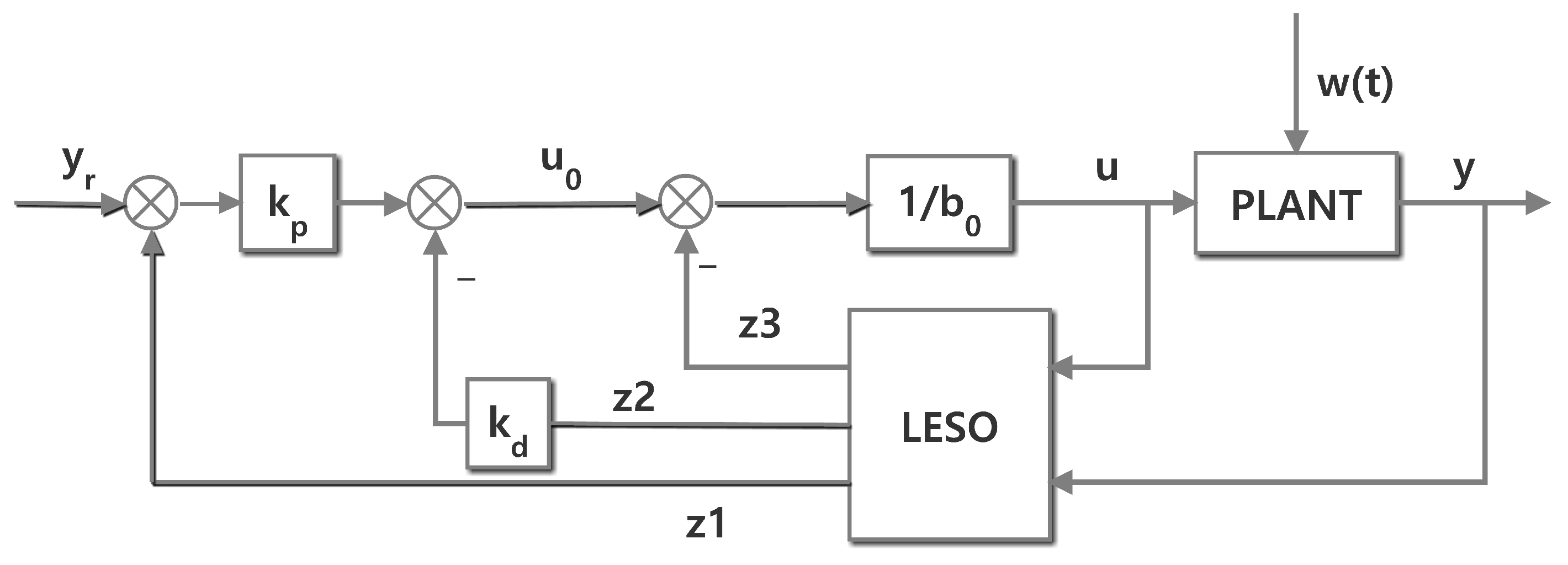
2.1. Traditional LADRC
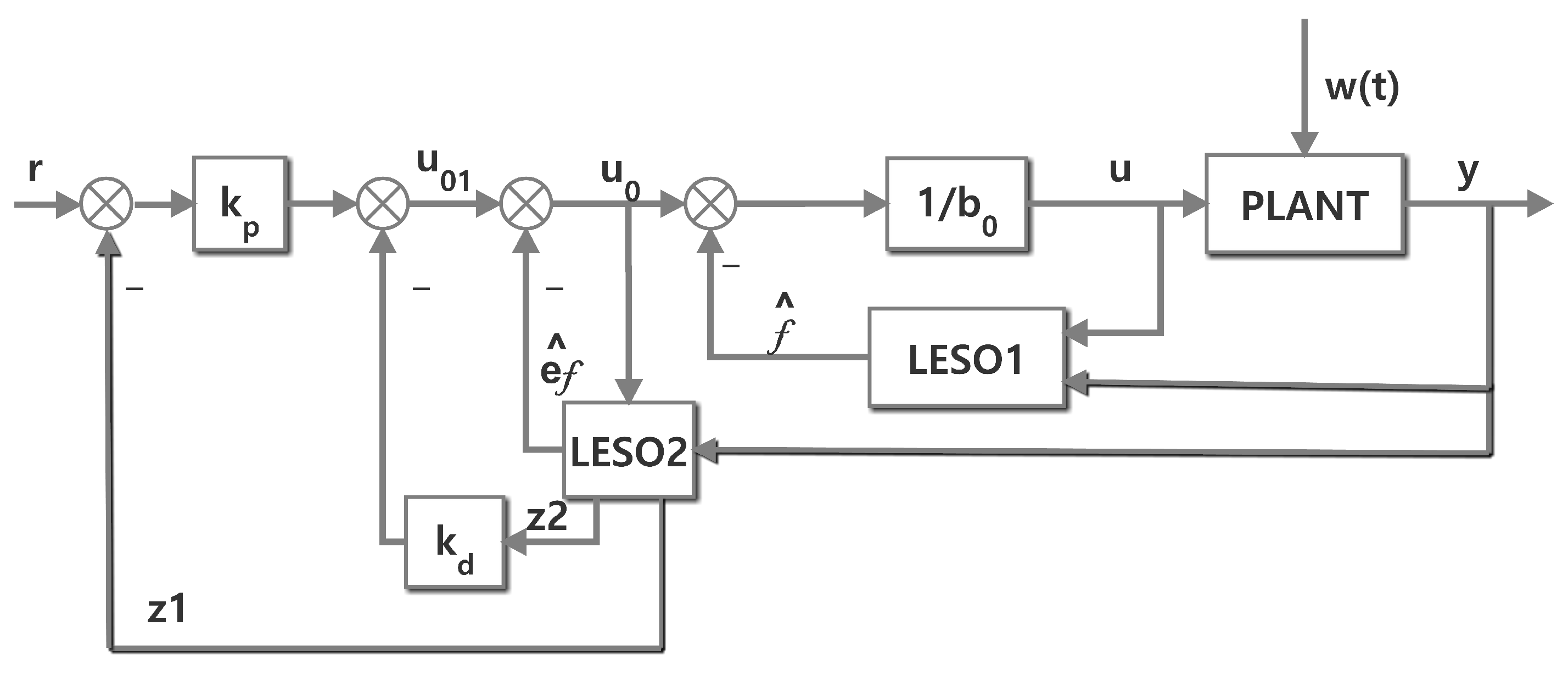
In the drum water level control system, a serial three-impulse controller is composed of three signals of drum water level Y ( s ) , steam flow D ( s ) , and feed water flow W ( s ) .
In order to compensate for the internal disturbance and external disturbance to the control system by feedforward method, the mathematical model of the water level system can be simplified to a second-order system, i.e., m = 2 , using LESO correlation description:
y ¨ = f ( y ˙ , y , w ) + b 0 u ,
where y is the output signal of the system, u is the control input signal of the system, b 0 is the gain of the controller, w is the external disturbance of the system, and f ( · ) is the total disturbance of internal disturbance plus external disturbance.
Define the state as x 1 = y , x 2 = y ˙ and x 3 = f . The total perturbation is extended to m + 1 = 3 order linear system, then the state space of Equation (1) is expressed as:
x ˙ = A x + b 0 B u + E f ˙ y = C x ,
where, A = 0 1 0 0 0 1 0 0 0 , B = 0 1 0 , E = 0 0 1 , C = 1 0 0 .
In LADRC, the LESO is the key link for real-time estimation and on-line compensation of the total disturbances of the system. Its task is to observe the states and total disturbances of the system according to the input and output data.
As the controller gain b ^ 0 = b 0 is greater than zero, the following third-order LESO is established:
z ˙ = A z + b ^ 0 B u + K e ,
where e = x z 1 = y z 1 is observer error.
k 1 k 2 k 3 = α 1 ω 0 α 2 ω 0 2 α 3 ω 0 3 ,
α i = m + 1 ! i ! m + 1 i ! ( i = 1 , 2 , 3 ) ,
where K = [ k 1 k 2 k 3 ] T is the observer gain vector. K is chosen to put all of the observer eigenvalues at ω 0 for the ease of tuning. Here, ω 0 is referred to as the observer bandwidth. The LESO characteristic equation designed is as follows:
λ = s 3 + ω 0 α 1 s 2 + ω 0 2 α 2 s 1 + ω 0 3 α 3 = ( s + ω 0 ) 3 .
Such configuration can not only maintain the stability of the system, but also give a better transition process, and simplify the parameters as the observer bandwidth.
The linear state error feedback (LSEF) is designed as a PD. The controller is designed as follows:
u 0 = k p ( r y ) k d y ˙ u = u 0 z 3 b ^ 0 ,
since Z Y , the closed-loop dynamic equation of the system can be approximately written as:
y ¨ + k d y ˙ + k p y = k p y r ,
where k p is a proportional coefficient, k d is a differential coefficient, and y r is the water level setting value. According to the parameter tuning method of linear ADRC, the proportion and differential coefficients are determined as: k p = ω c 2 , k d = 2 ω c . Here, ω c is referred to as the controller bandwidth. The structure diagram of the LADRC is shown in Figure 1.

2.2. ILADRC

Liu [30] proved that two same low-order state observers are equivalent to a high-order ESO in series, and the low-order state observers adopt uniform parameters. This method not only guarantees the quality of control, but also reduces the number of parameters that need to be adjusted for the extended state observer, which reduces the difficulty of parameter setting. At present, the LADRC has simple structure, relatively mature parameter setting rules, and more convenient application than nonlinear ADRC. Inspired by the paper [30], in order to improve the disturbance rejection performance of ADRC, an IADRC for drum water level is designed by adding the same LESO and introducing the estimated error value of total disturbance on the basis of the structure of LADRC. The added extended state observer (LESO2) and the original extended state observer (LESO1) adopt uniform parameters, which not only ensure the control quality, but also reduce the number of parameters to be tuned, and simplify the difficulty of parameter tuning.
The structure of the ILADRC is shown in Figure 2.
If u in Equation (7) is substituted into Equation (1), the original system can be reduced to:
y ¨ = f ( y ˙ , y , w ) + u 0 z 3 ,
where z 3 is the estimate of f ( y ˙ , y , w ) . When z 3 accurately estimates f ( y ˙ , y , w ) , then
z 3 = f ^ f ( y ˙ , y , w ) = x 3 .
Substituting Equation (10) into Equation (9), we can get:
y ¨ = f ( y ˙ , y , w ) + u 0 f ^ u 0 .
Therefore, the original system is transformed into an integral series form. e f is defined as the estimated error of the linear observer for the total disturbance:
e f = f ( y ˙ , y , w ) f ^ .
Substitute Equation (12) into Equation (11) to simplify:
y ¨ = f ( y ˙ , y , w ) + u 0 f ^ e f + u 0 .
e f can be observed by the actual output quantity y and the virtual control quantity u 0 in the control process. Therefore, its observed value e f ^ can be obtained by adding an observer with the same structure before the existing LESO. u 01 is a new virtual control quantity after adding observer LESO2. It is defined as:
u 01 = k p ( r y ) k d y ˙ .
The relationship between the control variable u 0 and the virtual control variable u 01 is shown in Equation (15). The control law u can be obtained by adjusting the observed e f ^ to u 01 .
u 0 = e f ^ + u 01 u = u 0 f ^ b 0 .
Equation (13) is transformed into the integral series form of Equation (16).
y ¨ = e f e f ^ + u 01 = u 01 .
Thus, the ILADRC structure introduces the estimation error e f of the total disturbance and compensates for its observation. It can enhance the control system’s ability to restrain the unknown disturbance.

2.3. Parameter Setting

The parameter b 0 in the extended state observer represents the variation range of the total disturbance value. Its function is to make the control system reach stability quickly. The larger parameter b 0 is selected, the larger 1 b 0 u can be, thus speeding up the output response rate. Generally, when setting parameter b 0 , b 0 is set as a large value to keep the system in a sufficiently large stable region, and then set from large to small according to the step response curve until satisfactory dynamic performance is achieved.
The parameter ω c refers to the parameter tuning method of LADRC. Through a lot of parameter setting experience, it can be obtained that in actual design, the controller bandwidth can be set as ω c = 10 / t (t is the settling time of the system) and then be adjusted slowly to obtain the expected dynamic characteristics of the control system. The selection of observer bandwidth ω 0 is based on the general law of LADRC parameter setting ω 0 = 3 5 ω c , and then is adjusted slowly to obtain the satisfactory dynamic characteristics of the control system.

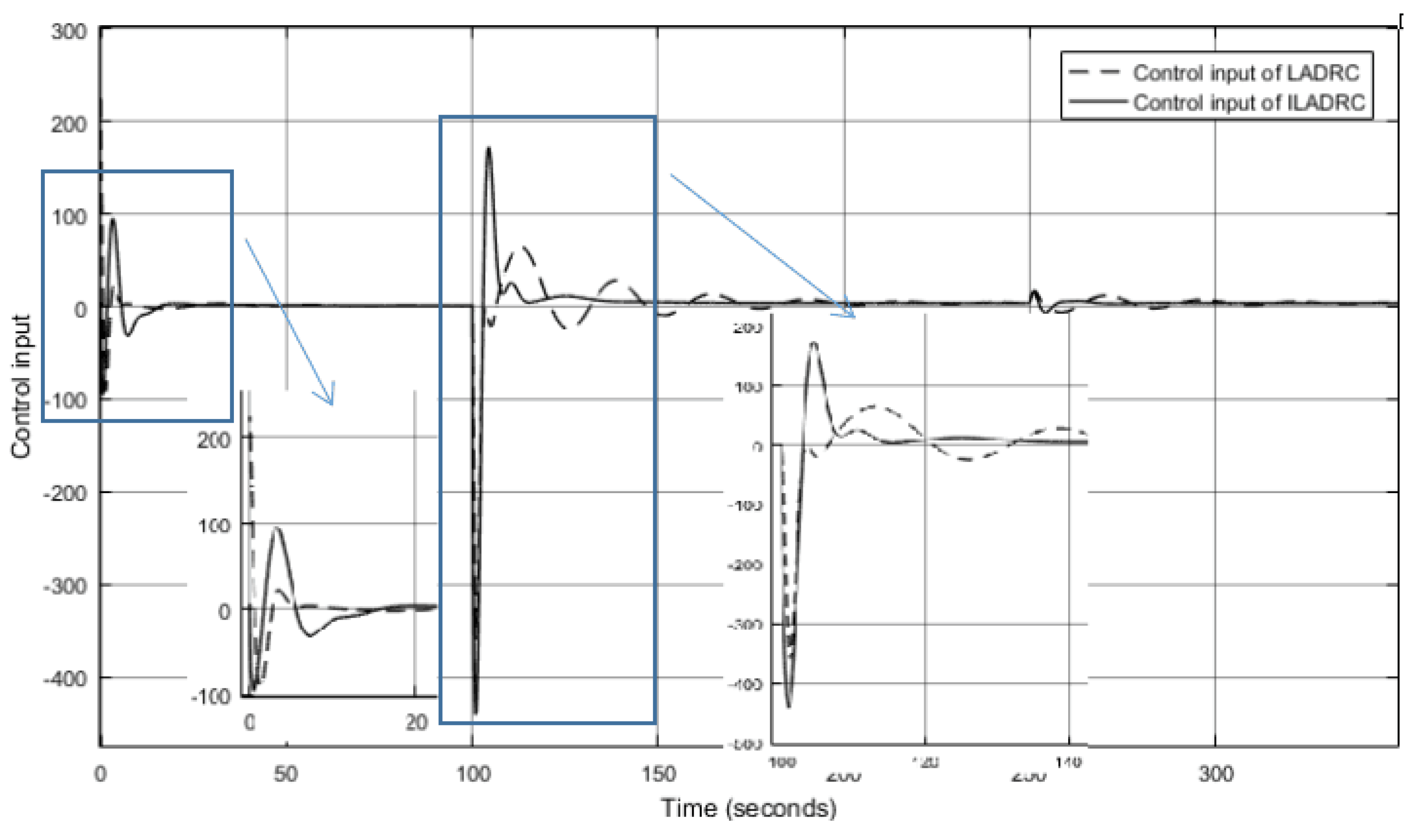
3. Simulation and Performance Analysis of Drum Water Level ILADRC

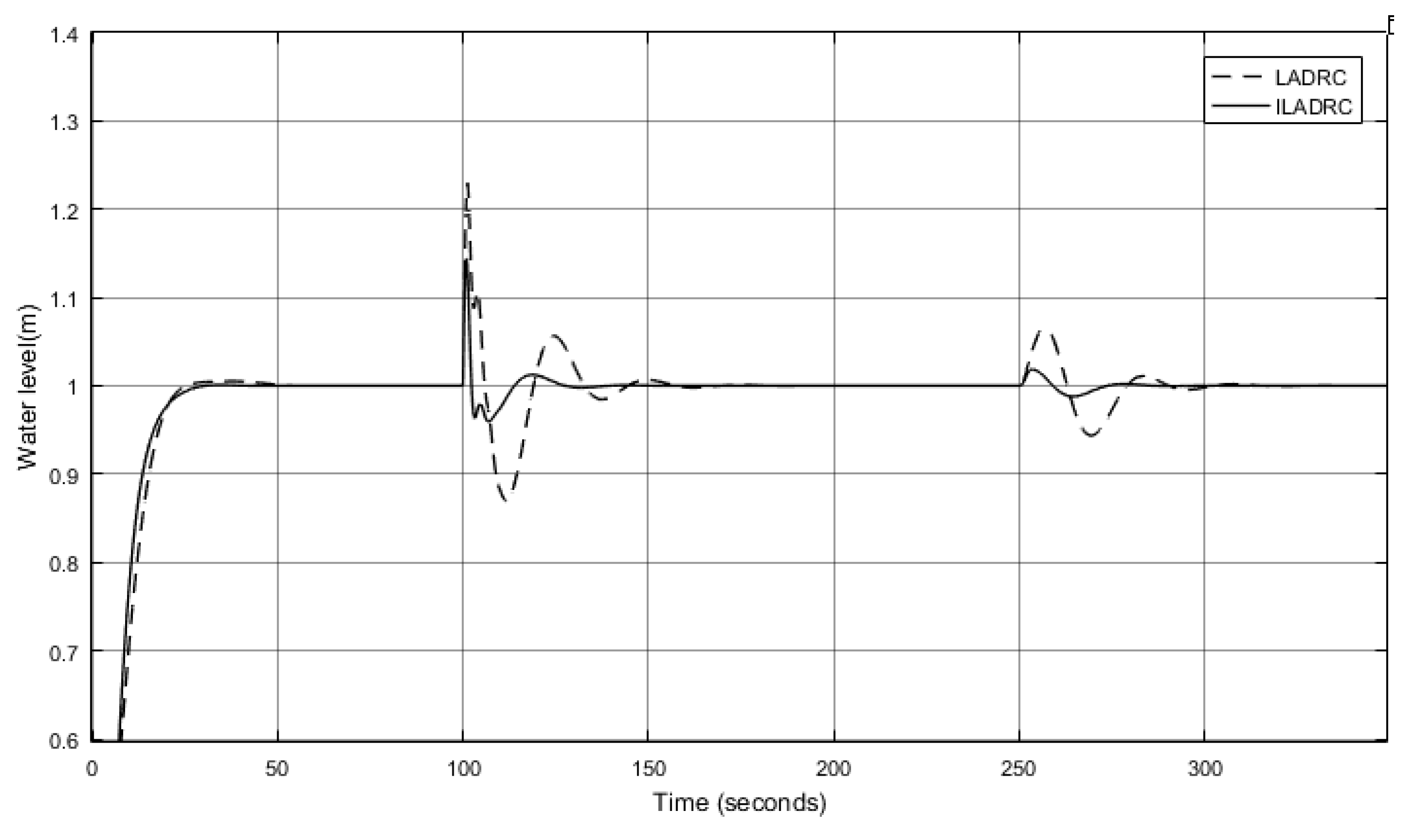
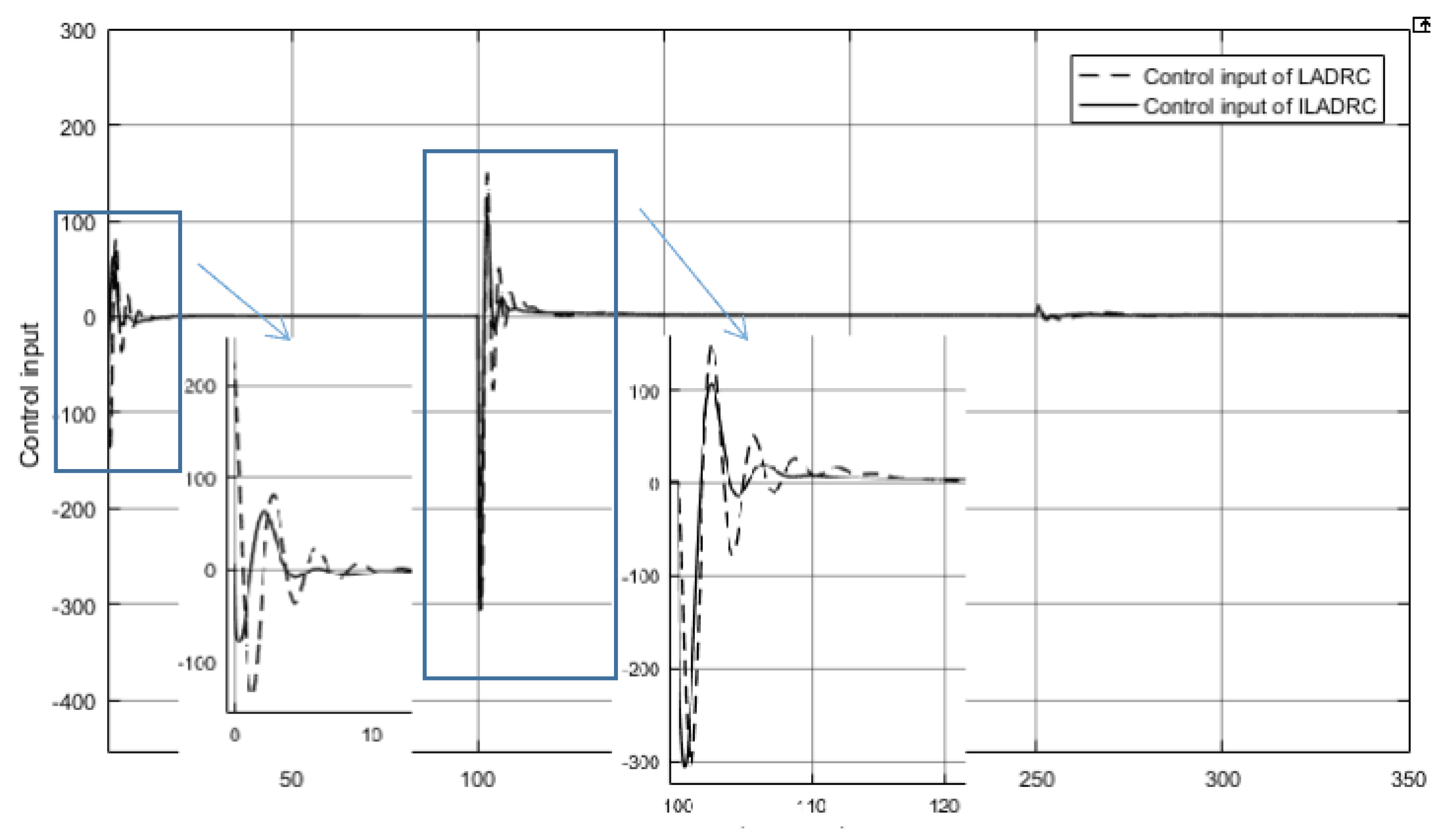
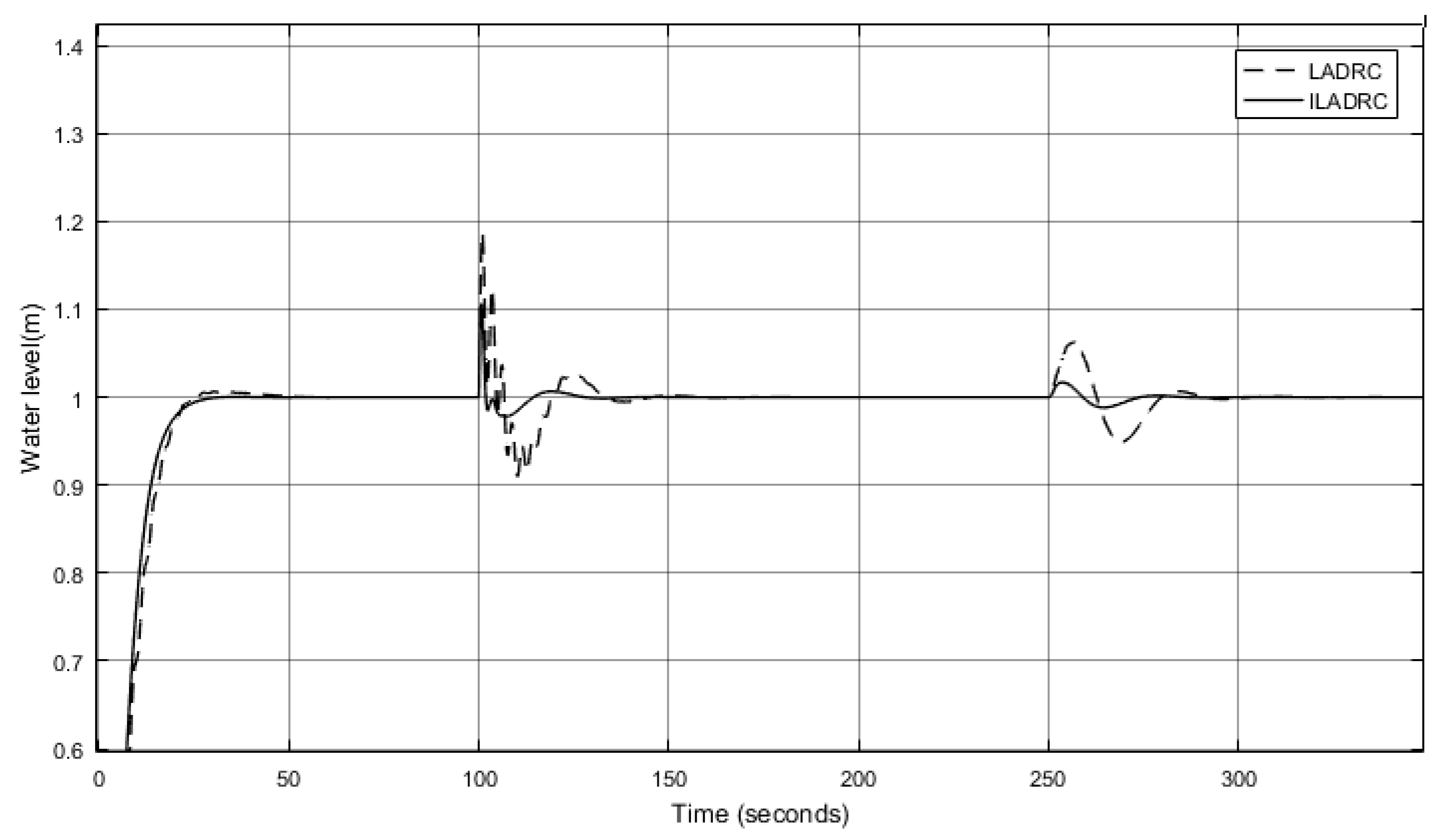
3.1. Performance Analysis under External Disturbance

In the drum water level control system, a cascade three-impulse controller is composed of three signals of drum water level Y ( s ) , steam flow D ( s ) , and feed water flow W ( s ) . The transfer function model of the drum water level system is shown in Figure 3.
In Figure 3, the control output of the main circuit is set to U ( s ) . The measurement error of water level in the main circuit and the loss of boiler connection are set to N 1 ( s ) . In the secondary circuit, the measurement error of flow meter and the disturbance of variable working condition are set to N 2 ( s ) . G V ( s ) is a mass transfer function from W(s) to feed water control valve. G D ( s ) is a transfer function from D ( s ) to Y ( s ) . G W ( s ) is a transfer function from W ( s ) to Y ( s ) . H D ( s ) is the transfer function of steam flow feedforward device. H W ( S ) is the transfer function of feed water flow feedback device. H Y ( s ) is the transfer function of the water level feedback device. G c 2 ( s ) is a sub-controller. G c 1 ( s ) is the main controller.
The initial value of drum water level is 0 and the set water level is y r = 1 . The transfer function and related parameters of the control object of the drum water level control system in a power plant are as follows:
G W ( s ) = λ s ( T s + 1 ) = 0 . 037 s ( 30 s + 1 ) G D s = 3 . 045 s 0 . 037 15 s 2 + s ,
H D ( s ) = H W ( s ) = 0 . 0174 G V ( s ) = 20 H Y ( s ) = 1 .
By tuning the controller, when the main controller is LADRC and ILADRC respectively, system parameters are shown in Table 1.
In order to investigate the performance of the system under external disturbance, when t d 1 = 100 s, the steam flow D ( s ) changes from 0.5 to 2. When t d 2 = 250 s, the secondary circuit interference N 2 ( s ) changes from 0 to 2. The comparative simulation of LADRC and ILADRC is shown in Figure 4.
The comparison of the variations of control input between LADRC and ILADRC is shown in Figure 5. As can be seen from Figure 5, the control input peak of ILADRC is smaller than that of LADRC and the fluctuation is smaller. According to the output energy of the controller input system through the control channel, ILADRC consumes less energy than that of LADRC.
The following performance indicators are defined to measure the dynamic performance of the system:
(1) Settling time
y ( t ) y r ε ,
where y r is the reference input and y ( t ) is the actual output. The selection of parameter ε usually depends on the requirement of control accuracy and needs to be larger than the amplitude of observation noise. At this time, t is the system Settling time.
(2) Overshoot
Assuming that the time when the system output reaches the first peak is t p , the overshoot θ is defined as:
θ % = y ( t p ) y ( ) y ( ) × 100 % .
The following performance indexes are defined to measure the anti-interference performance of the system.
(1) Recovery time
y ( t d 1 ) y ( t d ) ε ,
where y ( t d ) is the stable output before adding disturbance, and y ( t d 1 ) is the actual output. The choice of parameters generally depends on the requirement for control accuracy. t d is the time to add distractions. Then, the disturbance recovery time t r is written as:
t r = t d 1 t d .
(2) Dynamic landing
Suppose that the time for the system output to reach the first wave peak value is t d p , then the dynamic landing η is defined as:
η % = y ( t d p ) y ( ) y ( ) × 100 % .
The control accuracy is set as 2 % . t r 1 is the recovery time after adding interference at time t d 1 . η 1 is the dynamic landing after the introduction of disturbance at time t d 1 . t r 2 is the recovery time after adding interference at time t d 2 . η 2 is the dynamic landing after the introduction of disturbance at time t d 2 . The simulation results of LADRC and ILADRC are shown in Figure 4. The dynamic performance index and anti-interference performance index of LADRC and ILADRC are compared. The data is shown in Table 2.
As can be seen from Figure 4 and Table 2, the Settling time of LADRC and ILADRC is similar, and the overshoot of LADRC is 5.8 times that of ILADRC. Compared with the interference recovery time of the main circuit, LADRC is 2.7 times that of ILADRC. The secondary circuit interference recovery time of LADRC is 26 s, while that of ILADRC is 0 s. When the main loop is disturbed, the dynamic decline of LADRC is 1.6 times that of ILADRC. When the secondary loop is disturbed, the dynamic decline of LADRC is 3.6 times that of ILADRC. The dynamic performance of ILADRC is better than that of LADRC. The interference recovery of ILADRC in main and secondary loops is much better than that of LADRC, and the dynamic landing is much better than that of LADRC. It shows that ILADRC has better anti-interference performance when external interference is added.

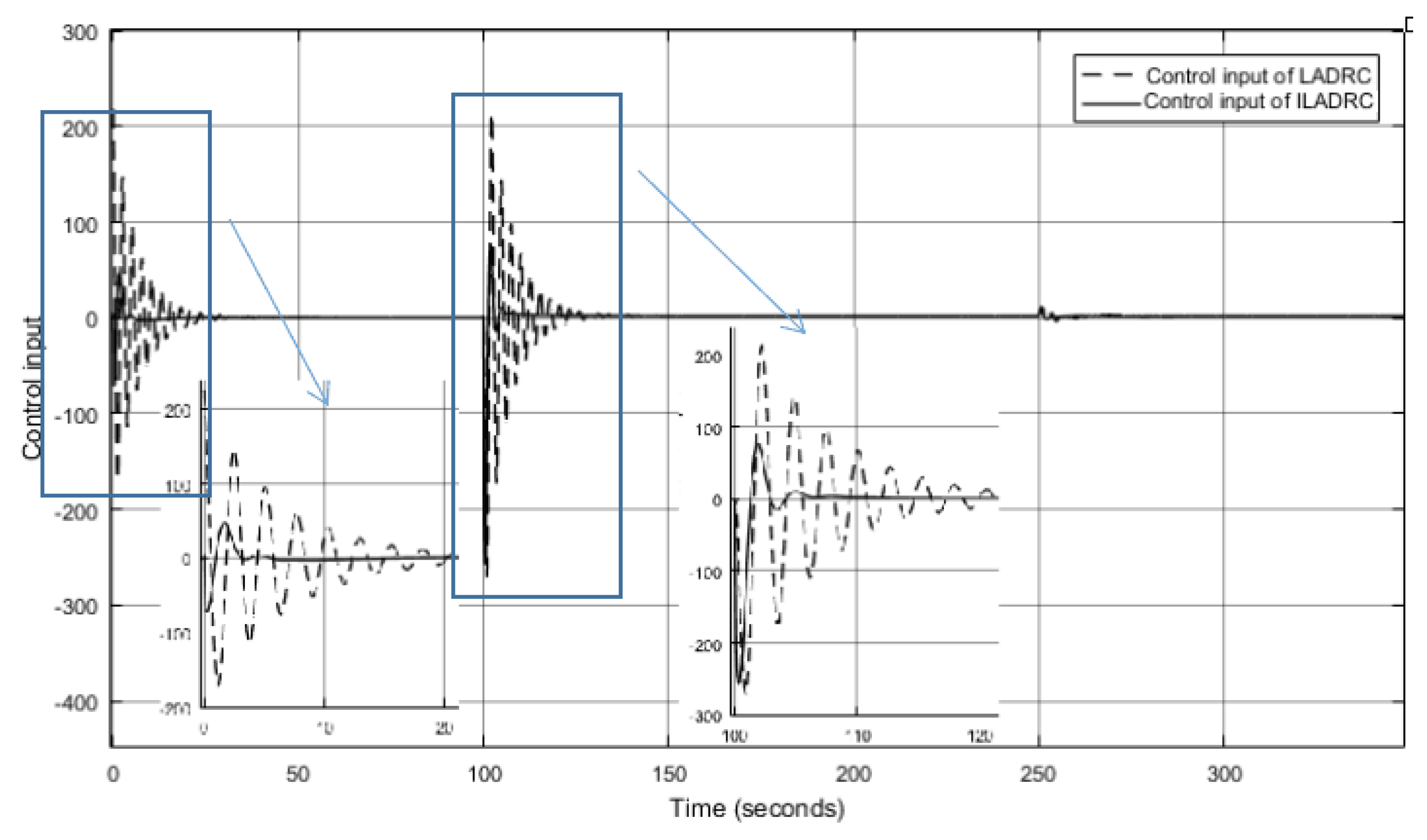
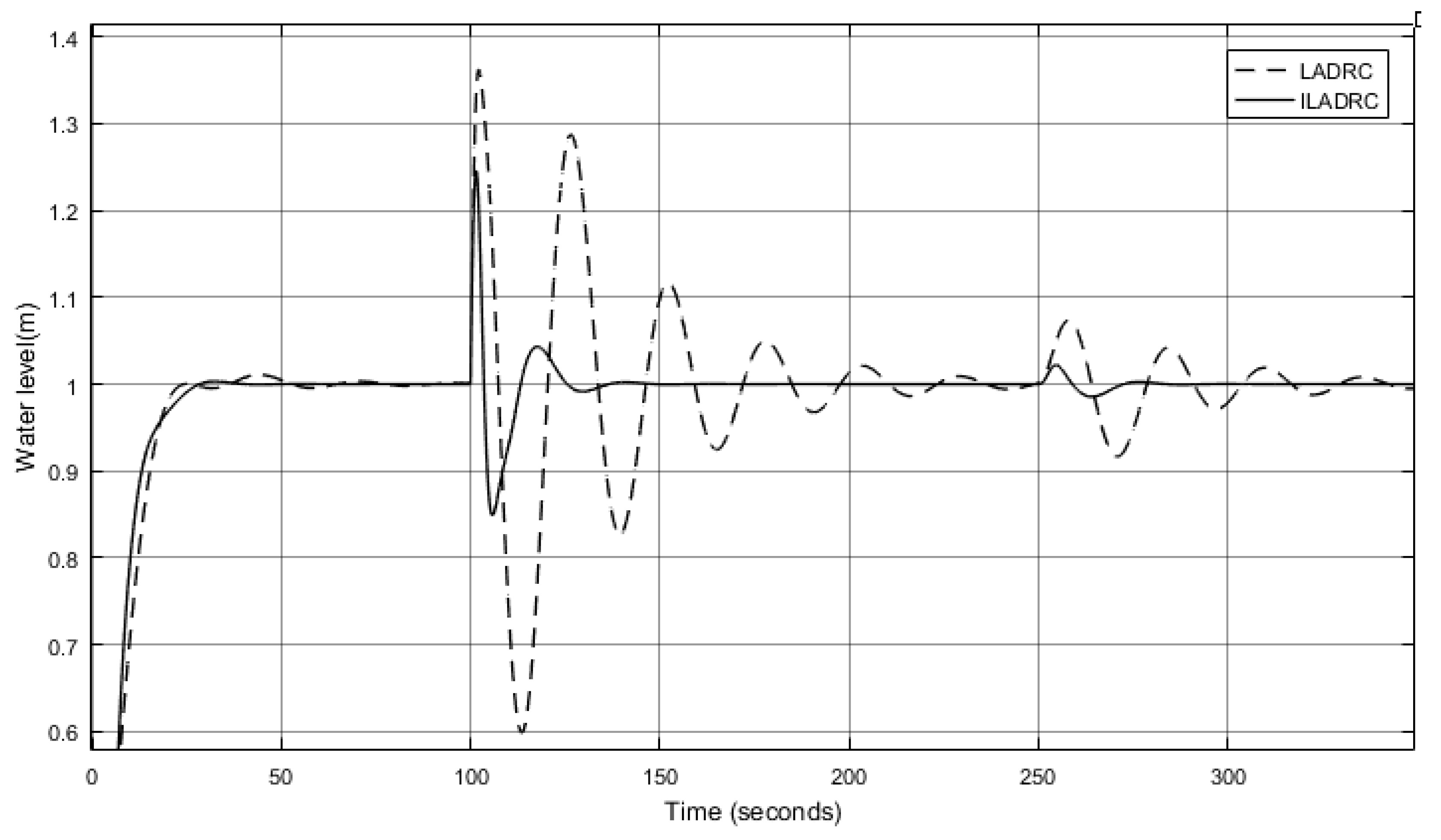
3.2. Robustness Analysis

The control performance of the system after the transfer function changes is discussed. Increase λ = 0 . 04 and decrease T = 20 , so the G W is significantly increased, and the transfer function G W is changed to:
G W ( s ) = 0 . 04 s ( 20 s + 1 ) .
The comparative simulation of LADRC and ILADRC is shown in Figure 6.
The comparison of the variations of control input between LADRC and ILADRC is shown in Figure 7. As can be seen from Figure 7, In the case of the model parameter G W increasing, the control input peak of ILADRC is smaller than that of LADRC, and the fluctuation is smaller. According to the output energy of the controller input system through the control channel, ILADRC consumes less energy than that of LADRC.
With the model parameter λ reduced to 0.02 and T increased to 40, the G W is significantly reduced, that is, the G W is changed to:
G W s = 0 . 02 s ( 40 s + 1 ) .
The comparative simulation of LADRC and ILADRC is shown in Figure 8.
The comparison of the variations of control input between LADRC and ILADRC is shown in Figure 9. As can be seen from Figure 9, in the case of the model parameter G W decreasing, although the control input peak of method ILADRC is larger than that of LADRC, the fluctuation is smaller.
The dynamic performance and anti-interference performance of LADRC and ILADRC are compared, and the results are shown in Table 3.
As can be seen from Figure 6 and Figure 8 and Table 2 and Table 3, the Setting time of LADRC and ILADRC is relatively stable. When G W is increasing, the overshoot of LADRC is 13 times that of ILADRC. When disturbance is added to the main loop, the dynamic landing of LADRC is 1.7 times that of ILADRC. When disturbance is added to the secondary loop, the multiple becomes 3.7. The recovery time of LADRC is obviously greater than that of ILADRC. When G W is decreasing, the overshoot of LADRC is 3.4 times that of ILADRC. The recovery time of LADRC is 4.8 times that of ILADRC. When disturbance is added to the main loop, the dynamic landing of LADRC is 1.5 times that of ILADRC. When disturbance is added to the secondary loop, this multiple becomes 3.4. The recovery time of LADRC is 50 s, while that of ILADRC is 0 s. The experimental data show that both are more sensitive to G W decreasing. The ILADRC’s indexes change very little and are more stable. ILADRC has better adaptability and robustness to the changes of model parameters.

4. Conclusions

In this paper, an ILADRC for drum water level is designed by adding the same LESO and introducing the estimated error value of total disturbance. The extended LESO2 and the original LESO1 adopted uniform parameters. The method of adjusting parameters that we summarized is simple and effective. The anti-interference performance and robustness of traditional LADRC and ILADRC for drum water level are simulated and analyzed under external disturbance and model parameters changing. The results show that, compared with LADRC, ILADRC of the drum water level control system has good dynamic characteristics, strong anti-interference ability, and strong robustness.
In theory, the proof of robust stability needs further study. In practice, it is necessary to build an experimental platform for real industrial field environment. In order to realize it in the actual industrial process, further and more detailed research is needed.

Author Contributions

Conceptualization, C.P. and J.S.; formal analysis, C.P., Y.Z. and J.S.; investigation, C.P. and Y.Z.; methodology, C.P.; supervision, J.S.; writing—original draft, C.P. and Y.Z.; Writing—review and editing, C.P., Y.Z. and J.S.

Funding

This research was partially financially supported by the National Natural Science Foundation of China under grants 61533012 and 91748120.

Conflicts of Interest

The authors declare no conflict of interest.

References

  1. Feng, L.Q. Research on Boiler Drum Water Level Control Based on Neural Network. Master’s Thesis, North China University of Science and Technology, Tangshan, China, 2018. [Google Scholar]
  2. Zhao, W. Design of Improved ADRC for Drum Water Level Regulation of Ship Boiler. Navig. China 2018, 41, 35–37. [Google Scholar]
  3. Jin, J.R.; Huang, H.S.; Sun, J.M.; Pang, Y. Study on Fuzzy Self-Adaptive PID Control System of Biomass Boiler Drum Water. J. Sustain. Bioenergy Syst. 2013, 3, 93–98. [Google Scholar] [CrossRef] [Green Version]
  4. Wang, J.; Meng, Q. Research on optimal control system of boiler drum water level based on LQR. In Proceedings of the 2011 International Conference on Transportation, Mechanical, and Electrical Engineering (TMEE), Changchun, China, 16–18 December 2011; pp. 1092–1094. [Google Scholar]
  5. Huang, Q.; Song, S.; Lin, X.; Peng, K. Research on water level optimal control of boiler drum based on dual heuristic dynamic programming. In International Symposium on Neural Networks; Springer: Berlin/Heidelberg, Germany, 2011; pp. 455–463. [Google Scholar]
  6. Zhao, R.; Wang, X.; Teng, F. The PID control system of steam boiler drum water level based on genetic algorithms. In Proceedings of the 2014 IEEE Chinese Guidance, Navigation and Control Conference, Yantai, China, 8–10 August 2014; pp. 1983–1986. [Google Scholar]
  7. Wang, J.H.; Meng, Q.J. Water Level Control of Boiler Drum Based on PFC-PID. J. Univ. Jinan 2012, 26, 171–174. [Google Scholar]
  8. Swarnakar, A.; Marquez, H.J.; Chen, T. A new scheme on robust observer-based control design for interconnected systems with application to an industrial utility boiler. IEEE Trans. Control Syst. Technol. 2008, 16, 539–547. [Google Scholar] [CrossRef]
  9. Senanayaka, J.S.L.; Karimi, H.R.; Robbersmyr, K.G. Sensorless small wind turbine with a sliding-mode observer for water heating applications. In Proceedings of the IECON 2015-41st Annual Conference of the IEEE Industrial Electronics Society, Yokohama, Japan, 9–12 November 2015; pp. 863–868. [Google Scholar]
  10. Mystkowski, A. Lyapunov Sliding-Mode Observers With Application for Active Magnetic Bearing Operated With Zero-Bias Flux J. Dyn. Syst. Meas. Control 2019, 141, 041006. [Google Scholar] [CrossRef]
  11. Han, J.Q. ADRC and Its Applications. Control Decis. Mak. 1998, 13, 19–23. [Google Scholar]
  12. Han, J.Q. ADRC Ttechnique—A Control Technique that Estimates and Compensates for Uncertainties; National Defense Industry Press: Beijing, China, 2008. [Google Scholar]
  13. Han, J.Q. An Extended State Observer for a Class of Uncertain Objects. Control Decis. 1995, 10, 85–88. [Google Scholar]
  14. Cheng, Q.M.; Zheng, Y.; Du, X.F.; Guo, R.Q. Three-element Drum Water-level Cascade Control System Featuring ADRC based on High Order Controller Design. J. Eng. Therm. Energy Power 2008, 23, 69. [Google Scholar]
  15. Gao, Z. Scaling and bandwidth-parameterization based controller tuning. In Proceedings of the American Control Conference, Denver, CO, USA, 4–6 June 2003; Volume 6, pp. 4989–4996. [Google Scholar]
  16. Gao, Z. Active disturbance rejection control: A paradigm shift in feedback control system design. In Proceedings of the 2006 American Control Conference, Minneapolis, MN, USA, 14–16 June 2006; p. 7. [Google Scholar]
  17. Su, J.B. Robotic Un-calibrated Visual Serving based on ADRC. Control Decis. 2015, 30, 1–8. [Google Scholar]
  18. Su, J.B.; Qiu, W.B.; Ma, H.Y.; Woo, P.Y. Calibration-free Robotic Eye-hand Coordination based on an Auto Disturbance-rejection Controller. IEEE Trans. Robot. 2004, 20, 899–907. [Google Scholar]
  19. Xiang, G.F.; Huang, Y.; Yu, J.R.; Zhu, M.D.; Su, J.B. Intelligence evolution for service robot: An ADRC perspective. Control Theory Technol. 2018, 16, 324–335. [Google Scholar] [CrossRef]
  20. Medjebouri, A.; Mehennaoui, L. Active Disturbance Rejection Control of a SCARA Robot Arm. Int. J. Serv. Sci. Technol. 2015, 8, 435–446. [Google Scholar] [CrossRef]
  21. Liu, X.L.; Xiong, L.P. Mechanical arm active disturbance rejection control based on artificial bee colony algorithm. In Applied Mechanics and Materials; Trans Tech Publications: Zürich, Switzerland, 2014; pp. 1511–1514. [Google Scholar]
  22. Wang, L.; Su, J.B. Attitude Tracking of Aircraft based on Disturbance Rejection Control. Control Theory Appl. 2013, 30, 1609–1616. [Google Scholar]
  23. Wang, L. Observer-Based Disturbance Rejection Control Methodology and Performance Evaluation. Ph.D. Thesis, Shanghai Jiao Tong University, Shanghai, China, 2015. [Google Scholar]
  24. Tan, W.; Zhou, H.; Fu, C. Linear active disturbance rejection control for load frequency control of power systems. Control Theory Appl. 2013, 30, 1607–1615. [Google Scholar]
  25. Gao, Z.Q.; Li, S.; Zhou, X.S.; Ma, Y.J.; Shi, X.Q. Design of MPPT controller for photovoltaic generation system based on LADRC. Power Syst. Prot. Control 2018, 46, 52–59. [Google Scholar]
  26. Jiang, J.G.; Liu, Y.Q.; Guo, M.L. Linear Auto Disturbance Rejection Control System for Water Level in Drum. Therm. Power Gener. 2016, 45, 110–114. [Google Scholar]
  27. Fu, Y.M.; Wang, Y.H.; Guo, F. Design of Linear Active Disturbance Rejection Controller for Drum Water Level of Heat Recovery Boiler. Therm. Power Eng. 2018, 33, 83–89. [Google Scholar]
  28. Li, Z.J. Thermal Automatic Control System; China Electric Power Press: Beijing, China, 2001. [Google Scholar]
  29. Zhou, T.M. Improved Active Disturbance Rejection Control and Its Application to Thermal System in Power Plant. Master’s Thesis, North China Electric Power University, Beijing, China, 2017. [Google Scholar]
  30. Liu, X.; Li, D.H.; Jiang, X.Z.; Hu, X.J. Simulation study of auto disturbance rejection controller for high-order systems. J. Tsinghua Univ. 2001, 6, 95–99. [Google Scholar]
Figure 1. Structural diagram of linear active disturbance rejection control (LADRC).
Algorithms 12 00132 g001
Figure 2. Structural diagram of the improved linear active disturbance rejection controller (ILADRC).
Algorithms 12 00132 g002
Figure 3. Transfer function model of drum water level system.
Algorithms 12 00132 g003
Figure 4. Comparison of LADRC and ILADRC anti-interference performance.
Algorithms 12 00132 g004
Figure 5. Comparison of control input between LADRC and ILADRC.
Algorithms 12 00132 g005
Figure 6. Simulation of LADRC and ILADRC with the model parameter G W increasing.
Algorithms 12 00132 g006
Figure 7. Comparison of control input with the model parameter G W increasing between LADRC and ILADRC.
Algorithms 12 00132 g007
Figure 8. Comparison of LADRC and ILADRC with the model parameter G W decreasing.
Algorithms 12 00132 g008
Figure 9. Comparison of control input with the model parameter G W decreasing between LADRC and ILADRC.
Algorithms 12 00132 g009
Table 1. Parameters of LADRC and ILADRC.
LADRCILADRC
main-controller b 0 = 0 . 02 b 01 = 0 . 92
ω 0 = 1 . 12 ω 01 = ω 02 = 18
ω c = 0 . 28 ω c 1 = ω c 2 = 0 . 28
sub-controller k p = 1 . 2     k i = 0 . 35     k d = 5
Table 2. Control performance comparison.
TimeIndexLADRCILADRC
t = 0 s t / s 2121
θ 0.520.09
t = 100 s t r 1 /s3011
η 1 2314
t = 250 s t r 2 /s260
η 2 6.51.8
Table 3. Control performance comparison.
TimeIndex λ , T , G w . λ , T , G w .
LADRCILADRCLADRCILADRC
t = 0 st/s21202020
θ 0.650.051.10.32
t = 100 s t r 1 /s28810522
η 1 18.610.736.224.5
t = 250 s t r 2 /s260500
η 2 6.51.77.42.2

