Abstract
This paper presents a novel diagonal recurrent neural network hybrid controller based on the shared memory of real-time database structure. The controller uses Data Engine (DE) technology, through the establishment of a unified and standardized software architecture and real-time database in different control stations, effectively solves many problems caused by technical standard, communication protocol, and programming language in actual industrial application: the advanced control algorithm and control system co-debugging difficulties, algorithm implementation and update inefficiency, and high development and operation and maintenance costs effectively fill the current technical gap. More importantly, the control algorithm development uses a unified visual graphics configuration programming environment, effectively solving the problem of integrated control of heterogeneous devices; and has the advantages of intuitive configuration and transparent data processing process, reducing the difficulty of the advanced control algorithms debugging in engineering applications. In this paper, the application of a neural network hybrid controller based on DE in motor speed measurement and control system shows that the system has excellent control characteristics and anti-disturbance ability, and provides an integrated method for neural network control algorithm in a practical industrial control system, which is the major contribution of this article.
1. Introduction
In the complicated industrial systems, the control object model of the system is often unpredictable because of the frequent interference of the external environment, the input condition variable, and the high coupling degree and time variation. Conventional control, such as PID control method, is difficult to achieve the desired control performance or even cannot meet the control requirements of complex industrial systems [1]. The use of advanced control can overcome the shortcomings of conventional control, and bring significant economic benefits to industrial applications when applied properly. Advanced control refers to those uses the intelligent control and optimal control theory to evolve into a type of control method that project implementation is more difficult and the control structure is more complicated than the traditional control method [2], ensuring the efficiency of industrial control systems, improving productivity, and reducing energy consumption.
Due to the changing production conditions and the change of product technical standards, it is often necessary to continuously optimize and update the relevant control strategies in the control system. However, the existing advanced control strategy is very difficult to coordination with the control system, the implementation and update efficiency of the control strategy is low, and has brought many challenges to industrial production [3,4]. The main reason for this phenomenon is that the current advanced control technology mostly uses an independent software system through the OPC way and DCS system for data communication, and communicates with the DCS system through OPC mode. In [5], with OPC technology, the advanced control strategy implemented in MATLAB/LabVIEW is integrated with the network control system. Paper [6] studies a kind of boiler system based on OPC application and uses OPC technology to communicate the control algorithm developed by Simulink with WICC of Siemens industrial control configuration software. Paper [7] developed an OPC client user connection based on .Net advanced control software and DCS system. Moreover, the traditional advanced control algorithm software package is usually written in a variety of high-level language integrated into the controller, its execution process often uses the ‘black box’ feature, which makes it difficult for users to perform monitoring and online debugging of advanced control algorithms, and the application effect is not ideal.
At present, it is precisely because the algorithm execution mostly adopts the method of integration and plug-in. The independent algorithm model operating environment does not have the ability to transplant and share with each other in many different types of computing platforms, resulting in the high cost of development, operation, and maintenance of advanced control strategy in industrial applications. So, how to effectively implement and apply the advanced control strategy in the industrial control system and improve the stability and real-time performance of the whole system are the problems that need to be solved by the whole control engineering community.
Neural network control technology, as a kind of advanced intelligent control algorithm, can fully approximate the unknown nonlinear dynamic behavior of an object, you can make up for the limitation of the conventional PID method, and is used to solve some nonlinear system control problem that is difficult to modeling [8,9,10,11,12]. However, the commonly used multi-layer forward neural network is a static network, which must be used in the control system to determine the object model. For systems with little or no prior knowledge, this method is inaccurate and affects the identification and control. Diagonal recurrent neural network has the internal feedback mechanism that can be used for the dynamic response of the memory system, and it does not need to have detailed knowledge of objects when being applied to the identification and control of a system. It can effectively improve the robustness and adaptability of the control system, improving the control performance of the system [13,14,15].
This study proposes a novel Diagonal Recurrent Neural Network (DRNN) hybrid controller based on real-time database structure of memory, using the DE technology to build the algorithm execution mechanism, innovatively put forward the concept of advanced control execution carrier transformation, and realize the implementation of new techniques of neural network control algorithm in low computing performance controllers. Here, we provide a brief tutorial on DN technology. The idea of DE technology is to construct a computing environment that can explain and operate the configuration files in the different control station. The prerequisite for establishing this technique is that all technical characteristics of the control configuration can be represented in a fixed data structure. DE technology includes a real-time database structure based on memory, and software organization technical specification based on a Multi-Agent System (MAS). The data model of the control configuration is installed in the real-time database, and the DE completes all the tasks of the control station through periodic data updates. The MAS software organization is used as the transaction processing mechanism of the real-time database, which can automatically motivate specific agents from the changes of specific data, and accept the related real-time data update request. From the working principle of the Data Engine, it can be seen that the configuration of the different control station in the DE has been transformed into a real-time database with unified memory data update calculation and management issues [16,17,18], thus solving the problem of programming difficulties of collaborative control of heterogeneous control devices. IAPlogic (IAP: Industry Automation Platform) [19], a control logic configuration software corresponding to the DE, uses a unified graphical configuration programming language to describe the controlled object, provides intuitive configuration and transparent data processing, and can significantly reduce development debugging costs.
Built on such fundamental theoretical of DE, we have seen various innovations. With the help of this research, we can realize the complicated calculation and application of neural network control algorithms on various computing platforms such as PLC and PC, and support the neural network control algorithm to learn, train, and test on the lower computer, and break through the barriers of the PLC controller which can only carry on simple logic operation and control, greatly improving the system operation and control of real-time performance and stability, while supporting online configuration and debugging optimization, which helps to reduce the control system development and operation and maintenance costs [20,21]. The main reason for using PLC as the execution equipment is that it has very high reliability, stability, and affordability [22]. However, for a long time, PLC has been identified as a class of equipment that is not suitable for process control and complex network control. Therefore, the significance of this study is very important.
To demonstrate the feasibility and superiority of the combination of PLC, IPC, and DE technology, a novel diagonal recurrent neural network hybrid controller was made in this paper and a DC motor speed measurement and control system is built. The neural network control strategy can run directly in the PLC, IPC-based control station of the speed control system, the use of methods is no different in nature from the conventional control. There is no longer a need to configure a high-end computer running independent advanced control software to operate an advanced control algorithm. The real-time database structure based on memory makes the diagonal recursive neural network controller not need offline training to obtain its optimal parameter value so that it can track the actual speed signal in time. Through a lot of high speed measurement and controlled experimentation, it is proven that the neural network control configuration components integrated into the configuration software can better improve the advanced control strategies and control station of the communication efficiency, improve the real-time performance of the control strategy of online operation, and provide scientific validation experiments for practical engineering application.
The rest of the paper has the following structure: in Section 2 the main problem is stated, and the theoretical background of the DE is presented. A design method of the DRNN Hybrid Controller based on DE theory is presented in Section 3. In Section 4, the proposed control method to monitor and control the motor speed is explained, and the results are presented and discussed. Finally, Section 5 is devoted to conclusions.
2. Theoretical Background
2.1. Outline of DE
The DE is the software organization made up of the real-time database based on memory and a multi-agent system of real-time data processing, mainly composed of task scheduling, a device driver, and control configuration actuator. The real-time database is a dynamic image that controls the configuration data unit, and the data content is completely independent of the control station calculation instructions and computing resources. The control configuration data unit is the control unit that performs the calculations of analog and digital quantities, for example, a control unit that acquires an input signal, a control unit that performs addition, subtraction, multiplication, and division, a control unit that performs a Boolean logic calculation, a control unit that generates a function signal, and the control unit responsible for implementation of high and low alarm, these units adopt the expression form of graphical control components, and its modeling principle is shown in Figure 1.
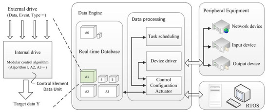
Figure 1.
Control component modeling and data engine structure.
Assuming that the control component is a multi-input single-output computing unit (the multiple outputs can be achieved with the configuration of multiple control components), then the data modeling is equivalent to the ‘projection’ of the data coding in a standard data space. In other words, the spatial structure of the corresponding data model is fixed regardless of the difference in the content of the control component. The differences between different control components are only reflected in the data content in the data model. The MAS software process is used to perform real-time database transaction tasks, specific interpretation, analysis, calculation, and update real-time database related matters.
The DE real-time database is embedded directly into the data memory area of the actual control station (PLC or IPC). According to the characteristics of the structure of the control component data model, the data memory in the control station is divided into several regions, and each region corresponds to a data model of the control component. To ensure that the control station in the implementation of the control configuration tasks in real-time, all the instruction operand address section should be pre-compiled into the contents of the data model in the process of generating control component data model. The operands of the control instructions employ decoding techniques to accommodate as much operation information as possible in a smaller memory space. With these techniques, the minimum operating cycle of the PLC-based advanced control algorithm controller has now reached a level of less than 20 ms.
2.2. Explanation of Data Engine Theory Operating Mechanism
The work of the DE is to control the configuration of data units as objects, and the real-time database will be continuously updated without interruption under the guidance of the computation sequence. Figure 2 shows the structure diagram of the DE control component in MAS software. When the control mode of a data unit body is pushed to the process of the communication module, the data carried by the data unit body is first transferred to each function processing sub-module according to the data structure and contents. These data include information about control component algorithm, control component calculation property parameters, calculation results of the previous calculation cycle, and control state of control components. The process retrieves the relevant operator from the algorithm execution library for the service request information represented by the relevant data to complete the update task of the specific data.
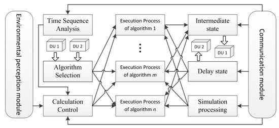
Figure 2.
The data engine control component performs a multi-agent structure.
To ensure the time-effectiveness of the control process, the traversal process of all control components must be completed within a specific operating cycle. Each of the MAS processes include an environmental perception module for monitoring the very state of the control station computing platform (dynamic reconfiguration is one of them), which can suspend the normal proxy service or temporarily change the contents of the proxy service to meet the control system security, stability, and economic operation of all the requirements.
2.3. Objective of the Control Method
Most of the current advanced control technology uses independent software system, through OPC implementing data communication with the DCS system, and the advanced control algorithm and its execution process often present the ‘black box’ feature, which makes it difficult for users to perform monitoring and online debugging of advanced control algorithms, and the application is not effective. The purpose of this study is to use DE technology to overcome the shortcomings of existing technology, providing an advanced method to implement integrated control technology in industrial control system: advanced control is integrated into the configuration software IAPlogic of the industrial control system based on the unified real-time shared memory by advanced control configuration components, the management, and configuration of advanced control components are in accordance with the conventional control components. The configuration interface is shown in Figure 3 below; the method has the following advantages:
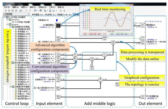
Figure 3.
Graphical configuration environment (IAPlogic).
(1) The data structure of the advanced control algorithm is the same as that of the conventional control algorithm. The computing resources of the advanced control algorithm are close to each other. The calculation process of the advanced control can be handled directly in the control station such as PLC and IPC. Therefore, it is no longer necessary to configure the high-end computer to run the advanced control algorithm.
(2) The advanced control algorithm is integrated into the configuration software in the form of advanced control components, which can greatly improve the real-time performance of the advanced control strategy.
(3) The functions of parameter modification, input/output, and calculation of intermediate variables in advanced control strategy can be realized through the simple combination of configuration components, and the calculation process of each group of components is monitored by the monitoring software so that the graphical configuration relationship very intuitive, real-time data processing transparent, which brings great convenience to the user’s online debugging.
(4) The advanced control and traditional control adopt uniform configuration and management modes. There is no essential difference between the resources used and the methods used, and user operation is very convenient, effectively reducing the costs of the development, commissioning, operation, and maintenance of industrial control systems. The integrated graphical configuration programming environment and reusable configuration components make it more flexible for engineers to handle heterogeneous controlled devices and more with online optimization of scalability.
3. Research on DRNN Hybrid Controller Based on DE
For the formulated DE technical in the previous section, a design method of the DRNN hybrid controller is proposed in this section based on DE technology. The neural network algorithm used in this method can be transplanted and shared in different kinds of computing platforms, and can support online configuration and debugging. At the same time, the online training and testing application of the neural network controller can be realized in the lower computer, and the real-time and stability elements of the control system can meet the needs of the industrial field long-term stable work. The detail of the control method will be presented in the following subsections.
3.1. Algorithm and Configuration Component Integration
3.1.1. Basic Principle of DRNN Algorithm
For complex process industry system, the controlled object is usually the more multiple input multiple output dynamic time-varying parameter system, it is difficult to establish an accurate mathematical model, at the same time, the precision of the conventional PID control method in nonlinear system control and decoupling control also make it difficult to achieve an ideal control effect. Neural network control technology, as a kind of intelligent control method, can fully approximate the unknown nonlinear dynamic behavior of an object, making up for the limitation of the conventional PID method. It is used to solve some difficult to the modeling of nonlinear system control problem. However, the multilayer forward neural network is a kind of static network, its application in the control system must first determine the model of object [23], for the system of unknown or little prior knowledge is inaccurate and affects the identification and control effect. The diagonal recurrent neural network has the internal feedback mechanism can be used to remember the dynamic response of the system, it can effectively improve the robustness and adaptability of the control system and improve the control performance of the system without knowing the detailed object knowledge in the system identification and control [24,25,26].
There are three layers of the structure of the diagonal recursive neural network, namely the input layer, the hidden layer, and the output layer, and its structure is shown in Figure 4. The implicit layer consists of a recursive neuron that receives only its own internal feedback, unrelated to other neurons. This simplifies the network structure, reduces the need to adjust the parameters, and accelerates the convergence speed.
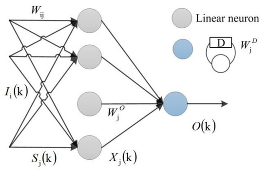
Figure 4.
Diagonal recursive neural network structure.
For any discrete moment k, is the ith input of the network. is the sum of the input of the implicit layer j, is the output of the recursive neuron, and the . is the output of the diagonal recursive neural network, , , and represent the weights of the input layer, the hidden layer, and the output layer.
The dynamic equation of the diagonal recursive neural network is then given as
The sigmoid function f(x), is used as the squashing function for all neurons and defined as
Information flows forward through the net from input to output. Note that as x tends to +∞, the value of f(x) tends to +1, while as i tends to −∞, f(x) tends to −1. When x is equal to 0 the value of f(x) is 0. As x tends to +∞ or −∞ the value of tends to 0, and when x is equal to 0 the value of is 0.5. The sigmoid function f(x) and its derivative function , are shown in Figure 5 (painted by MATLAB R2015b, the MathWorks, Inc., Shanghai, China).
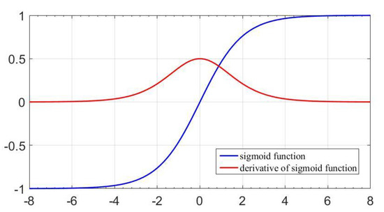
Figure 5.
Sigmoid function and derivative of sigmoid function.
The weights of , , and are iteratively updated by the output of the diagonal recursive neural network O(k)
The structure of the control system of the diagonal recursive neural network is shown in Figure 6, and there are two diagonal recursive neural network structures in the system. One as an identifier called the diagonal recursive neural network identifier (DRNI), the other one is called the diagonal recursive neural network controller (DRNC). This neural identifier is not used to estimate unknown parameters like in [27], neither to estimate the reference model directly, but to approximate the unknown sensitivity of the device . DRNC drives an unknown dynamic system that minimizes the error between the output of the device and the expected output. In this paper, a generalized dynamic Backpropagation (DBP) algorithm is used to train the DRNI network and the controller DRNC network. The current errors are also used to train the DRNN weights in the dynamic back propagation method [28].
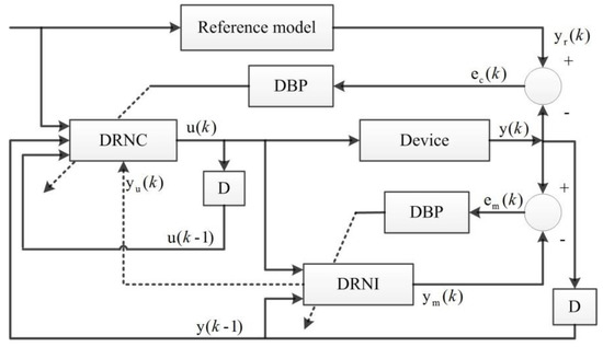
Figure 6.
Control system structure based on the DRNN.
3.1.2. Learning Algorithm of the DRNI
The current control signal u(k) produced by the DRNC network and the output of the device at the previous moment y(k−1) as the input to the DRNI network. The error between the output of the DRNI network ym(k) and the output of the device y(k) was introduced to the weight value updating formula, and modify the weight of the DRNI network. By training, the DRNI and DRNC network can get the more effective weight of the DRNC network.
The performance index function of the DRNI network was defined as
In this paper, both DRNI and DRNC network is trained by dynamic reverse propagation (DBP) algorithm, and the update formula of weight value in DRNI network can be rewritten as
where is the learning rate of the DRNI network, is the new weight, and is the current weight. The weights are iteratively updated for all the training patterns. is calculated according to Formula (3).
3.1.3. Learning Algorithm of the DRNC
The input of the DRNC controller network is the reference input r(k), the output of the device at the previous moment y(k−1), and the control signal of the previous moment u(k−1). The output of the DRNC network is the control signal of the device u(k). After several training cycles by using the DBP algorithm to adjust the weight of the DRNC network, the error between the output y(k) and the desired output yr(k) can be reached to a small value. However, it needs the device’s Jacobian information when training DRNC network, which is usually unknown, so DRNI is required to estimate the sensitivity information of unknown devices (Jacobian information) for controller DRNC.
The performance index function of the DRNC network was defined as
The update formula of weight value in DRNC network can be rewritten as
where is the learning rate of the DRNI network, represents the sensitivity of the device, for unknown controlled devices, it is difficult to obtain by direct calculation, but if DRNI network has better training, it can approximate it as
Therefore, by training the DRNI and DRNC network continuously, can get the more effective weight of the DRNC network, which is the algorithm of the control system based on the diagonal recursive neural network.
3.2. Summary of DRNN Hybrid Controller Based on DE Theory
In view of the current investigation of neural network controller in industrial application, neural network algorithms run in the upper computer are often processed in non-real-time databases, and the real-time data collected by the control station also needs to be transferred to the upper computer, which affects the real-time performance of system control to a certain extent. So, a common neural network hybrid controller implementation method is proposed in this paper.
Step 1—Constructing the topology of controller algorithm by using data unit. According to the structure of the designed DRNN neural network and the learning methods of the network, the topology of the DRNN network algorithm is constructed by the data unit of the configuration software IAPlogic, and the time series judgment and analysis of the calculation order of each unit module are carried out, and then the variable data calculation and signal transfer process of the control algorithm are determined.
Step 2—Establish a mapping relationship between the data unit and the generic middleware. The function of the general middleware is to establish a connection between the computing unit module and the target platform, which is composed of a set of memory-based database, transaction scheduler, an algorithm executing program, and a middleware program. The algorithm information of the DRNN neural network topology is sent to the general middleware, the program which reflects the data unit of the network node is structured and digitally encoded according to a certain mapping relationship, and the mapping relationship between them will be established. The factors that should be considered in digital coding include real-time data, data type, identification of data in the system, control logic of the calculation unit module and calculation timing between modules, communication address, and so on.
Step 3—Establish a mapping relationship between general middleware and target platform. Analyze the programming specification of the target platform instruction system and establish a set of mapping relationship is between the structured digital coding system of the common middleware and the target platform instruction system.
Step 4—Parsing the mapping relationship between general middleware and target platform and generating the code supported by the target platform. Using the middleware program to analyze the mapping relationship between the digital code of the general middleware control algorithm and the program code of the target platform, the encoding algorithm is transformed into executable code supported by different platform computing hardware and its instruction system by using the program code automatic generation method. Figure 7 depicts the architecture of our abstract platform based on DE Theory.
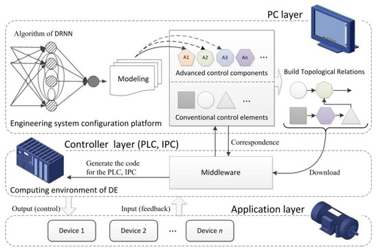
Figure 7.
The abstract platform architecture of the DRNN hybrid controller.
3.3. Implementation of the DRNN Control Algorithm
Unlike offline learning, online learning attempts to update the knowledge base of the neural network incrementally after the presentation of each training sample, rather than learning data samples based on a particular offline learning scenario [29]. The topology of the DRNN controller in this study contains two parts: the instruction data that does not change during the execution of the control algorithm, and the dynamic data that participates in real-time computation and update which only needs to provide timely feedback and dynamic updates to the real-time data parts when the entire control system is running. When the DE receives a learning request, the calculation threads of the control algorithm for all data units are frozen. The data unit responsible for online learning and training is continuously receiving the feedback control signal from the actual device and is then sent to a temporary data buffer of the control station, where it retrieves the DRNN related execution algorithm from the algorithm execution library to self-iterate the data unit in time, completing the task of updating the weight data, and realizing the goal of online learning.
Numerical simulations of DRNC and DRNI were performed on an IPC platform (model IPC-S2221), a set of sinusoidal analog signals were used for confirmatory experiments. The actual output and the reference output of the controlled device in the diagonal recurrent neural network control system are observed to verify the feasibility of this study. Assuming a single input single output nonlinear device, its difference equation can be described as
The difference equation of the reference model is
where the reference input is .
The goal is to determine the device input u(k) make the where the is an appropriate minimum. In this experiment, the neurons nodes in the DRNC and DRNI network were 7 and 5 respectively, , the calculation cycle of the control station ; as mentioned above, not presetting (off-line training) of the weight vector was necessary. Special requirements are not necessary for the initial conditions of the first two controllers. A real-time dynamic nonlinear learning law (as opposed to off-line training procedure) of the weight vector is proposed for the neural network by using DE technology, initial conditions of the weight vector were random number is the random number between 0 and 1, and the seven nodes were used to approximate u(k).
The simulation results are obtained when implementing the DRNN during 100 s. Figure 8 shows the evolutions of the errors of the during the learning online process. The convergence of the weights of the identifier and controller are shown in Figure 9, respectively, where all of the INN weights converge after 20 s. Calculated by the IPC control station calculation cycle Ts = 100 ms, equivalent to the online iterative training nearly 200 times. The number of iterations is similar to that of some online learning research [30,31,32,33,34].
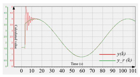
Figure 8.
The estimated and real numerical simulations signals. Initial speed guess before 3 s is 1.6.
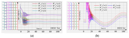
Figure 9.
Convergence of the DRNN weights for the reference mode: (a) DRNC, (b) DRNI.
Under the simulation conditions, the errors are significantly large and chattering in the early stages, but reduce fast when the weights converge and the performance approaches approximately optimal values. It is shown that the control system of DRNN based on DE technology has a good self-regulation and adaptive ability that can quickly recover to a stable state and the anti-interference ability is stronger.
4. Motor Experimental Setup and Results
4.1. Experimental Setup
The proposed DRNN controller validation framework was applied to real motor speed measurement and control experiment platform environmental modeling case studies to demonstrate the scientific DE technology that is used in industrial applications of neural network control. A snapshot of the experimental setup is illustrated in Figure 10; it shows the architecture is divided into engineering station (Human–Machine Monitoring layer), control layer, executive layer, and application layer. In this paper, IPC (IPC-S2221) based on QNX control system is used as a controller to run the DRNN control algorithm logic through the embedded DE software, and realize the self-iterative continuous operation of the algorithm components in the form of data update, and then generate the final control signal through the shared memory sent to the corresponding output component of the PLC that is the executing device, by the PLC CS1W-DA08C analog output module output to the voltage input end of the TaiDa servo driver for control.
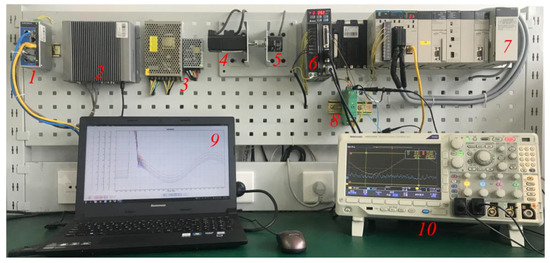
Figure 10.
Components of the experimental setup. 1: Router, 2: IPC, 3: 10V and 5V power supply, 4: Servo motor, 5: Optical electrical rotary encoder, 6: Server driver, 7: PLC, 8: D/A channels, 9: Engineer station, 10: Oscilloscope.
The feedback thread of the control loop is used as the speed sensor by the Omron C6B2-C optical-electrical rotary encoder converts the geometric displacement of the servomotor into pulse digital, the resolution of the encoder is set to 60P/R, that is used to simulate the proximity switch signal in actual industrial applications. A PLC CS1W-CT021 high-speed counting module was used for acquisition which the maximum input frequency is 500 kHz, in order to carry out a real-time testing. The speed is calculated by the DE software embedded in Omron PLC and then fed back to IPC for neural network control algorithm iterative operation, eventually forming closed-loop control. The D/A channels are used to provide the command signal outputs to be shown in the oscilloscope.
The structure of the entire control system and the flowchart of control information are shown in Figure 11, through the engineer station, the corresponding version of the DE software downloaded to IPC and PLC respectively to build a unified memory real-time sharing mechanism. The application of a unified graphical configuration component as a programming language, effectively solves the problem of integrated control of heterogeneous devices. This article is mainly used in the collaborative control of Omron PLC and SuoQi IPC, which fully combines the reliability and stability of PLC as the actuator and the powerful computing ability of the IPC, which effectively improves the anti-disturbance ability of the control system and the implementation efficiency of nerve network control algorithm. From the cost analysis, it not only reduces the cost of separately developing the ladder diagram of the PLC and developing the IPC based on C #, Java, and XML, but also the implementation process of the algorithm is transparent that convenient for engineers to carry out unified debugging under the condition of online operation, reducing the running risk of the system. The logic diagram of the coordinated control configuration is shown in Figure 12 below. Also, the entire system is based on Industrial Ethernet communication, which has good real-time function and stability on data transmission and reduces the control delay error caused by communication delay.
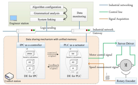
Figure 11.
Block diagram of DRNN closed-loop compound control system based on DE Theory. AO: Output analog component, AI: Input analog component, SM: Speed measurement component.
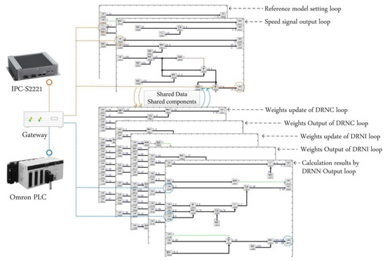
Figure 12.
Collaborative control configuration diagram of different hardware devices.
4.2. Tracking Performance
The performance of the DRNN hybrid controller based on DE technology is investigated at different operating conditions, the control system parameter settings of the DRNN and the initial conditions were the same with them. The dynamic behaviors of the PI control and with neural network control are shown in Figure 13 at no load conditions.
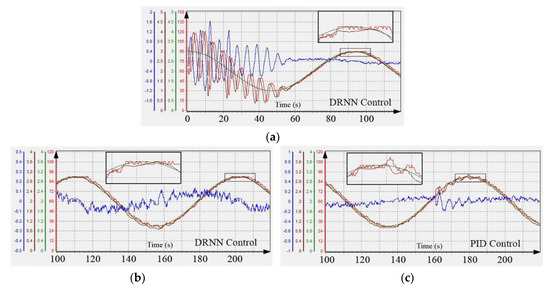
Figure 13.
Reference tracking performance comparison between diffident control strategies, red line: Speed feedback value, green line: Reference model , brown line: control signal , blue line: Evolution of the errors for the rotational speed. (a) The initial control performance with RDNN; (b) The steady state control performance with RDNN; (c) The steady state control performance with PID.
Compared with the simulation experiment in the ideal state, there are many uncertainties in the practical application research, such as multi-variable strong coupling, strong interference, feedback hysteresis, and unknown parameter information of the nonlinear controlled device. Therefore, the corresponding difference equation cannot be obtained. This paper assumes that the controlled motor is an unknown dynamic system, and the DRNI is used to estimate the sensitivity information of the unknown equipment for the DRNC. Figure 13a shows the reference signal with parameter uncertainties and its estimations given by the DRNN based on the DE technology. It can be seen that despite these uncertainties leading to the failure to achieve online learning speed and tracking characteristics under the pure simulation conditions shown in Figure 8, the proposed DRNN controller estimates the reference signal very well and the error can gradually converge within a reasonable range after 58 s.
Figure 13b,c present the performance comparison during steady state operation respectively, and it is observed that the reference tracking performances are nearly same with PI and neural based drive system. From the partial magnification diagram can be found when the weights are converging, the control signal calculated by DRNN controller tends to be smooth and gradually fit the reference model , but in the PID control curve, it still fluctuates. The steady-state error signal by variance was analyzed with the oscilloscope real-time sampling in this paper to determine the degree of deviation from the volatility. The results are shown in Table 1 below. Although, in the results, it is observed that the PI control is tuned to give an optimum response at steady state, the neural network control has faster response time, smaller steady-state error, and better tracking performance.

Table 1.
Error variance comparison between PI and neural controllers during the steady state operation.
4.3. Control Performance
For a particular step signal, Figure 14 shows the control performance of the DRNN hybrid controller with different learning rates. It can be seen that the value of the learning rate on the control performance when the learning rate is small, the step response time longer, but it does not overshoot. However, when the learning rate increases gradually, the step response time is shorter, and the overshoot increases. In this experiment, when the learning rate is 0.02, it has the best control performance, which not only has short response time, but also no obvious overshoot.
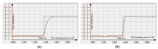
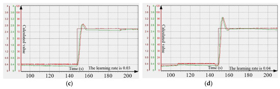
Figure 14.
Comparison of step control performance under different learning rates. (a) Performance curve when the learning rate is 0.01; (b) Performance curve when the learning rate is 0.02; (c) Performance curve when the learning rate is 0.03; (d) Performance curve when the learning rate is 0.04.
Based on the 0.02 optimal learning rate, we set up the disturbance experiment and the dynamic response experiment under the change of the reference model. Figure 15a shows the effect of a reference model change on motor speed control performance. When the controller reaches a steady state for a period, the weights have been trained and tend to converge. At this moment, the recognizer DRNI has adequately estimated the sensitivity information of the unknown motor device for the controller DRNC. Therefore, when the reference model changes from a sinusoidal signal to a constant signal, larger fluctuations do not appear. It should be noted that if the converted reference signal has a step characteristic (sharp increase in instantaneous error), we can observe from Figure 15b that the peak overshoot at the time of conversion and is quickly eliminated under the control of the DRNN controller.
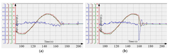
Figure 15.
Dynamic characteristics analysis of reference model switching condition. (a) Curve converted to line under continuous switching; (b) Non-continuous switching.
In the disturbance experiment, two-second disturbance bias signals were applied to the output of the equipment and the speed feedback respectively to simulate the disturbance of the actual control site. Experimental results are shown in Figure 16, a paranoid signal is applied at 160 s, the control system can quickly return the error signal to the weight vector calculation unit of the identifier DRNI for weight updating (the number of neurons in the DRNI network is set to 5), and adjust back to the steady state within 15 s. It shows that the neural network hybrid controller has good robustness in dealing with disturbance.
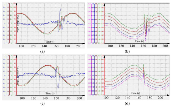
Figure 16.
Dynamic characteristics analysis of disturbance condition. (a) Adaptive curve under equipment output disturbance; (b) Weight update curve under equipment output disturbance; (c) Adaptive curve under feedback signal disturbance; (d) Weight update curve under feedback signal disturbance.
4.4. Dynamic Reconstruction Performance
To reflect the adaptability and high availability of DRNN hybrid controller in an unintended environment, a unique concept of dynamic reconfiguration based on DE technology was introduced in this paper, which is a synonym of runtime evolution, the ability to change a system’s functionality and topology while it is running. The benefit is application consistency and service continuity for the system while it is being updated [35,36].
One of the significant features of the controller based on the DE technology is that the control logic topology is written by the host computer and then downloaded to different lower-level machines for execution control, and the data of control execution devices are interconnected and interoperable under the mechanism of shared memory, the data transformation process of each data unit can be monitored on the host computer in real time. Therefore, when an extreme condition such as disconnection or a crash occurs on the engineer station in the host computer, it will not affect the implementation of IPC and PLC on the control strategy, when the host computer resumes grid connection, it can be monitored immediately. As shown in Figure 17a,b, the engineer station (network disconnected) was shut down manually at 120 s, and the engineer station (connected to the grid) was restarted at 200 s, the control system can still operate in the steady state and no interference appears.
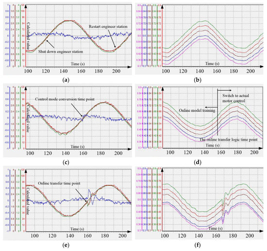
Figure 17.
Dynamic characteristics analysis curves under control mode switching between advanced control and normal control. (a) Control curve under online delivery without disturbance; (b) Weight update curve under online delivery without disturbance; (c) Change control method (PID converted to DRNN); (d) Weight update curve under change control method; (e) Dynamic additive difference equation to modify motor internal characteristics; (f) Weight update curve under dynamic additive difference equation.
Besides, the neural network hybrid controller can be switched online without disturbance. As can be seen from Figure 17c, when changing the control mode from conventional PID control to DRNN control, there is no significant dynamic tracking error similar to the one shown in Figure 13a that results from the convergence of the weight update during the training start-up phase, but only a very small range of overshoot fluctuations. This is because, in the process of PID control, we also study the DRNN control logic online at the same time. When the error value is smaller than certain smaller value, we can download the topology of the DRNN control logic to the control station to achieve interference-free switch. It should be noted that the online learning samples are from the reference model, so the ideal learning environment generated feedback error value is small, and in the moment of switching, the learning sample is transformed into the measured value of the actual motor speed, resulting in a sudden change in the error feedback signal, which is also the main reason for the small overshoot. As shown in Figure 17d, the weight update trend shows that the weight update curve is very smooth before switching. After switching to the DRNN control logic, the updating process of weights is adjusted in real time with the fluctuation of feedback errors, showing a certain degree of volatility.
In order to further study the dynamic reconfiguration of the controller, this paper set a group of experiments by modifying the characteristics of the controlled motor. In this paper, we superimpose a single-input single-output difference equation on an unknown controlled object, and try to dynamically modify the characteristic equation of the motor online to observe the performance of the DRNN hybrid controller. As shown in Figure 17e, the topology of a difference equation is superimposed on-line at the output of the DRNN control logic at 160 s. The difference equation is
It can be found that there is a certain amount of peak overshoot at the moment when the characteristics of the motor are changed. The cause of the peak overshoot is still due to the instantaneous increase of the feedback error, which leads to an increase of the calculated value of the weight during the iterative calculation of the weight and this phenomenon can be seen by the corresponding weight update curve of Figure 17f. However, since the process of reconfiguring the control logic on-line transmission takes place in a steady state, that is, the DRNN hybrid controller has been deeply learning the reference model so that the errors can be rapidly eliminated and show good robustness.
5. Conclusions
This paper presents a DE technology based on the real-time database and multi-agent system and discusses the concept and operation mechanism in detail. Developed advanced control strategy components based on this technology have the same data structure and the configuration mode with conventional control algorithm components; it can be directly used in PLC, IPC, and another machine for visual operation and debugging, with no need to configure a separate advanced control software to perform advanced control algorithm, improving the real-time performance of the online operation of the advanced control strategy to some extent. More importantly, DE technology: (1) enables the algorithm model to have a configuration programming environment that can be migrated and shared among different types of computing platforms; (2) realizes the interconnection and interworking of data between heterogeneous equipment control devices in engineering applications; (3) significantly reduces the development, operation, and maintenance costs of industrial applications for advanced control strategies; and (4) derived an advanced control technology in actual industrial control system.
A novel DRNN hybrid controller was made in this paper to demonstrate the feasibility and superiority of the combination of PLC, IPC, and DE technology. In Section 3, the topology structure of the diagonal recurrent neural network algorithm, the architecture of the controller, and the realization method were described in detail. Also, a numerical simulation of nonlinear equipment with known reference model was made for the DRNN controller proposed in this work. The results showed that the off-line training with extensive input data was not necessary, the system has a good self-regulation, adaptive ability, can quickly return to a stable state, and has strong anti-interference ability with the real-time dynamic nonlinear learning law of the weight vector.
The practical application research with motor speed measurement and control platform were made in this work, presented in Section 4. The results showed the good performance of the DRNN hybrid controller and the validity of the procedure to calculate the motor speed signal with motor parameter uncertainties. Also, the transient response from the steady state provided by the DRNN control has been best compared to conventional PID control.
The control system based on DE technology realizes the graphical configuration of the neural network control algorithm by way of dynamic reconfiguration, providing an innovative application method for neural network intelligent control theory in engineering implementation, which is a major contribution of this paper. The experimental results in Section 4.3 show that dynamically changing the topological structure of the control strategy will not cause much disturbance to the steady-state system. Therefore, the dynamic reconfiguration technology is no longer limited to the exception of the control system and the change of process conditions; it extends to the field of the dynamic evolution technology of intelligent control domain control algorithm, including the long-term continuous online optimization of the control system.
Despite all the achievements that have been made for DRNN control systems in the past decades, more efforts are still needed in the future, especially in the field of industrial control. In future studies, the DE architecture is planned to be deployed in the cloud of the Internet of Things. It will also be used to build the industrial cloud platform application of a neural network control algorithm, and research its close relationship with other systems such as the Internet of Things and multi-agent systems. This applied research will then reveal the values of control systems based on DE with an advanced control algorithm in broader perspectives.
Author Contributions
Conceptualization, S.Z.; methodology, S.Z., C.B. and Y.L.S.; software, C.B. and Y.L.S.; validation, C.B. and Y.L.S.; formal analysis, C.B.; investigation, S.Z., C.B. and Y.L.S.; resources, C.B.; data curation, C.B.; writing—original draft preparation, S.Z. and C.B.; writing—review and editing, S.Z. and C.B.; visualization, C.B.; supervision, S.Z.; project administration, S.Z.; funding acquisition, S.Z.
Funding
This work was supported by the Fuzhou Science and Technology Project Foundation of China (grant no. 2017-G-70).
Conflicts of Interest
The authors declare no conflict of interest.
References
- Namazov, M.; Basturk, O. DC motor position control using fuzzy proportional-derivative controllers with different defuzzication methods. TJFS 2010, 1, 36–54. [Google Scholar]
- Dotoli, M.; Fay, A.; Mariagrazia, M.; Seatzu, C. Advanced control in factory automation: A survey. Int. J. Prod. Res. 2017, 55, 1243–1259. [Google Scholar] [CrossRef]
- Bauer, M.; Craig, I.K. Economic assessment of advanced process control—A survey and framework. J. Process Control 2008, 18, 2–18. [Google Scholar] [CrossRef]
- Shao, G.D.; Latif, H.; Carla, M.V.; Denno, P. Standards-based integration of advanced process control and optimization. J. Ind. Inf. Integr. 2019, 13, 1–12. [Google Scholar] [CrossRef]
- Mahmoud, M.S.; Sabih, M.; Elshafei, M. Using OPC technology to support the study of advanced process control. ISA Trans. 2015, 55, 155–167. [Google Scholar] [CrossRef]
- Wu, M.L.; Wu, M.; Huang, J. Intelligent control system of water level for boiler drum based on OPC and MATLAB. In Proceedings of the 30th Chinese Control Conference (CCC), Yantai, China, 22–24 July 2011; pp. 4461–4464. [Google Scholar]
- Huang, Y.; Yan, L.X. Design of OPC Client Based on. NET for Advanced Control System. Adv. Mater. Res. 2014, 1037, 334–338. [Google Scholar] [CrossRef]
- Jain, L.C.; Seera, M.; Lim, C.P.; Balasubramaniam, P. A review of online learning in supervised neural networks. Neural Comput. Appl. 2014, 25, 491–509. [Google Scholar] [CrossRef]
- Hou, Z.G.; Cheng, L.; Tan, M. Decentralized robustad aptive control for the multi agent system consensus problem using neural networks. IEEE Trans. Syst. Man Cybern. Syst. Part B Cybern. 2009, 39, 636–647. [Google Scholar]
- Zhang, H.W.; Lewis, F.L. Adaptive cooperative tracking control of higher-order nonlinear systems with unknown dynamics. Automatica 2012, 48, 1432–1439. [Google Scholar] [CrossRef]
- Das, A.; Lewis, F.L. Cooperative adaptive control for synchronization of second-order systems with unknown nonlinearities. Int. J. Robust Nonlinear 2011, 21, 1509–1524. [Google Scholar] [CrossRef]
- Chen, G.; Song, Y. Cooperative tracking control of nonlinear multi-agent systems using self-structuring neural networks. IEEE Trans. Neural Netw. 2014, 25, 1496–1507. [Google Scholar] [CrossRef]
- Campolucci, P.; Uncini, A.; Piazza, F.; Rao, B.D. On-line learning algorithms for locally recurrent neural networks. IEEE Trans. Neural Netw. 1999, 10, 253–271. [Google Scholar] [CrossRef] [PubMed]
- Kumar, R.; Smriti, S.; Gupta, J.R.P. Diagonal recurrent neural network based adaptive control of nonlinear dynamical systems using lyapunov stability criterion. ISA Trans. 2017, 67, 407–427. [Google Scholar] [CrossRef]
- Mosavi, M.R. A comparative study between performance of recurrent neural network and Kalman filter for DGPS corrections prediction, Signal Processing. In Proceedings of the 2004 7th International Conference ICSP’04, Beijing, China, 31 August–4 September 2004; pp. 356–359. [Google Scholar]
- Zheng, S.; Ni, W.D. Research and Implementation of Dynamic Reconfiguration Technology in Distributed Control System. At. Energy Sci. Technol. 2009, 43, 724–729. [Google Scholar]
- Zheng, S.; Zhang, W.; Liu, C.L. Research on the configuration method of mobile robot and its realization. In Proceedings of the IEEE Chinese Control and Decision Conference, Guiyang, China, 25–27 May 2013; pp. 2877–2883. [Google Scholar]
- Zheng, Y.L.; Zheng, S. Cyber Security Risk Assessment for Industrial Automation Platform. In Proceedings of the IEEE International Conference on Intelligent Information Hiding and Multimedia Signal Processing, Adelaide, Australia, 23–25 September 2015; pp. 341–344. [Google Scholar]
- Zheng, S. Application of Platform Integration Control Technology in Ship. In Proceedings of the China Command and Control Conference, Beijing, China, 4–5 August 2014; pp. 77–82. [Google Scholar]
- Gupta, S.; Sharma, S.C. Selection and application of advance control systems: PLC, DCS and PC-based system. J. Sci. Ind. Res. 2005, 64, 249–255. [Google Scholar]
- Zhang, R.; Wu, S.; Gao, F.R. State Space Model Predictive Control for Advanced Process Operation: A Review of Recent Development. New Results Insight. Ind. Eng. Chem. Res. 2017, 56, 5360–5394. [Google Scholar] [CrossRef]
- Dumitru, I.; Iulia, N.; Fagarasan, I. A fuzzy PLC control system for a servomechanism. Intell. Control Syst. 2010, 43, 69–74. [Google Scholar] [CrossRef]
- Levin, A.U.; Narendra, K.S. Control of nonlinear dynamical systems using neural networks—Part II: Observability, identification, and control. IEEE Trans. Neural Netw. 1996, 7, 30–42. [Google Scholar] [CrossRef]
- Ku, C.C.; Lee, K.Y. Diagonal recurrent neural networks for dynamic systems control. IEEE Trans. Neural Netw. 1995, 6, 144–156. [Google Scholar] [PubMed]
- Ku, C.C.; Lee, K.Y. Nonlinear system identification using diagonal recurrent neural networks. In Proceedings of the International Joint Conference on Neural Networks, Baltimore, MD, USA, 7–11 June 1992; pp. 839–844. [Google Scholar]
- Kazemy, A.; Hosseini, S.A.; Farrokhi, M. Second order diagonal recurrent neural network. In Proceedings of the IEEE International Symposium on Industrial Electronics, Vigo, Spain, 4–7 June 2007; pp. 251–256. [Google Scholar]
- Ahmed-Ali, T.; Kenne, G.; Françoise, L.L. Identification of nonlinear systems with time-varying parameters using a sliding-neural network observer. Neurocomputing 2009, 72, 1611–1620. [Google Scholar] [CrossRef]
- Elbuluk, M.E.; Malik, E.; Liu, T.; Iqbal, H. Neural-network-based model reference adaptive systems for high-performance motor drives and motion controls. IEEE Trans. Ind. Appl. 2002, 38, 879–886. [Google Scholar] [CrossRef]
- Saad, D. On-Line Learning in Neural Networks; Cambridge University Press: Cambridge, UK, 1998; pp. 59–62. [Google Scholar]
- Humphrey, G.B.; Maier, H.R.; Wu, W.; Mount, N.J.; Dandy, G.C.; Abrahart, R.J.; Dawson, C.W. Improved validation framework and R-package for artificial neural network models. Environ. Model. Softw. 2017, 92, 82–106. [Google Scholar] [CrossRef]
- Liu, G.; Liang, J.; Lan, G.; Hao, Q.; Chen, M. Convolution neutral network enhanced binary sensor network for human activity recognition. In Proceedings of the 2016 IEEE SENSORS, Orlando, FL, USA, 30 October–3 November 2016. [Google Scholar]
- Menghal, P.M.; Jaya Laxmi, A. Neural network based dynamic simulation of induction motor drive. In Proceedings of the 2013 International Conference on Power, Energy and Control (ICPEC), Sri Rangalatchum Dindigul, India, 6–8 Febuary 2013; pp. 566–571. [Google Scholar]
- Nguyen, T.L. Adaptive dynamic programming-based design of integrated neural network structure for cooperative control of multiple MIMO nonlinear systems. Neurocomputing 2017, 237, 12–24. [Google Scholar] [CrossRef]
- Fernando, J.L.; Godpromesse, K.; Francoise, L.L. A novel online training neural network-based algorithm for wind speed estimation and adaptive control of PMSG wind turbine system for maximum power extraction. Renew. Energy 2016, 86, 38–48. [Google Scholar]
- García, J.; Palomo, F.R.; Luque, A.; Aracil, C.; Quero, J.M.; Carrión, D.; Gámiz, F.; Revilla, P.; Pérez-Tinao, J.; Moreno, M.; et al. Reconfigurable distributed network control system for industrial plant automation. IEEE Trans. Ind. Electron. 2004, 51, 1168–1180. [Google Scholar] [CrossRef]
- Almeida, J.P.A.; Sinderen, M.V.; Pires, L.F.; Wegdam, M. Platform-independent Dynamic Reconfiguration of Distributed Applications. In Proceedings of the IEEE 10th International Workshop on Future Trends in Distributed Computing Systems (FTDCS 2004), Suzhou, China, 28 May 2004; pp. 286–291. [Google Scholar]
© 2019 by the authors. Licensee MDPI, Basel, Switzerland. This article is an open access article distributed under the terms and conditions of the Creative Commons Attribution (CC BY) license (http://creativecommons.org/licenses/by/4.0/).