Abstract
This paper presents the hardware implementation of a stand-alone Electrical Capacitance Tomography (ECT) system employing a Field Programmable Gate Array (FPGA). The image reconstruction algorithms of the ECT system demand intensive computation and fast processing of large number of measurements. The inner product of large vectors is the core of the majority of these algorithms. Therefore, a reconfigurable segmented parallel inner product architecture for the parallel matrix multiplication is proposed. In addition, hardware-software codesign targeting FPGA System-On-Chip (SoC) is applied to achieve high performance. The development of the hardware-software codesign is carried out via commercial tools to adjust the software algorithms and parameters of the system. The ECT system is used in this work to monitor the characteristic of the molten metal in the Lost Foam Casting (LFC) process. The hardware system consists of capacitive sensors, wireless nodes and FPGA module. The experimental results reveal high stability and accuracy when building the ECT system based on the FPGA architecture. The proposed system achieves high performance in terms of speed and small design density.
1. Introduction
The Electrical Capacitance Tomography (ECT) is one of the recent techniques applied for visualizing industrial applications. It has the ability to generate images capturing the dynamic behavior of the process [1]. The ECT is a non-invasive and non-intrusive modality which measures capacitance data from an array of electrodes evenly mounted around a vessel. Dielectric permittivity properties of materials inside the imaging area change the measured data and enable the ECT to generate tomographic images describing these materials’ distribution [2]. Compared with the other electrical tomography techniques such as Magnetic Resonance Imaging (MRI) and Computed Tomography (CT), the ECT has a high temporal resolution [3]. Some of the advantages of the ECT technique over the other methods are low cost, high speed, and robustness [4].
Typically, the ECT system has an array of electrodes mounted around an object to measure the capacitance values across that object to build an image describing its dielectric distribution [2]. The array contains 8–12 electrodes separated by an earthed ring to eliminate any interference between the electrodes. The mutual capacitance is measured between each different pair of the electrodes where one electrode, in turn, is raised as a transmitter and the rest as receivers. Some recent ECT systems have high measurements’ sensitivity in a range of femto-Farads (fF) to atto-Farads (aF). However, one challenge is the long time consumed in the data acquisition process (average 1.15 ms) and the image reconstruction procedure around 1.25–1.4 ms [5].
The ECT system can visualize distribution of dielectric or conductive materials [6,7]. Multi-phase flows such as oil/gas in oil pipelines and gas/solid in fluidization processes are common dielectric ECT applications. One ECT application for conductive materials is casting process where the generated images describe a distribution of metal inside a flask [8]. The capacitance measurements are affected by the amount of the metal between the electrodes. The collected data are used by a proper image reconstruction algorithm to generate the images [9,10,11].
The cross-section view of the ECT system for imaging the Lost Foam Casting (LFC) process is shown in Figure 1. There are 12 electrodes attached to the wall of the flask surrounding a foam pattern, embedded in compressed sand, where a molten metal will be poured. The boundaries of the foam pattern represent the imaging area. Each capacitive sensor ( to ) is a pair of electrodes [12]. In order to eliminate the outside disturbance, the flask is grounded. The measurements are wirelessly sent based on Mote technology to a base station connected to a PC where the images will be generated. The system is flexible and portable because it uses wireless technology. The sensors operate simultaneously at different operating frequencies [13].
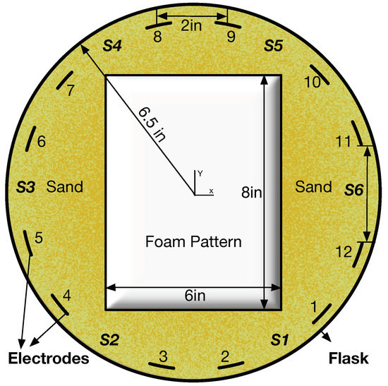
Figure 1.
An ECT system for imaging conductive materials.
Two consecutive procedures have to be followed to create the images: the first is called a forward problem and the second is called an inverse problem. The forward one concerns creating a Finite Element Model (FEM) simulating the real ECT system taking spatial materials’ distribution and generates corresponding capacitance measurements. While the inverse problem takes the measurements as inputs and applies an image reconstruction algorithm to create a tomographic image [14]. The image reconstruction algorithms are classified into two categories: linear and nonlinear. The linear ones are simple and fast; therefore, they are applied for high temporal and fast dynamic applications, but, usually, output images from these algorithms are blurred. While nonlinear reconstruction algorithms are complex and iteratively solve linear algebra transformations in order to generate high-quality images.
The ECT system has been widely implemented with software algorithms running on general- purpose processors. Commands are sent by the processor to measure the capacitance between sensors, construct the tomography images, and display it. Typically, the drawbacks of these systems are big size, high power consumption, high cost, as well as hard adaptation to the new system requirements. However, when a real-time operation is required, dedicated hardware must be designed [1]. Therefore, a parallel VLSI architecture is proposed to reduce the consumed time by the high computation image reconstruction algorithm and increase the throughput to more than 500 f/s. The new proposed architecture makes the ECT systems more applicable for high dynamic applications.
The reconfigurable computing technology is driven by the Field Programmable Gate Arrays (FPGAs) [15]. Advantages of the FPGAs such as the terrific logic capacity, the intense flexibility of their use, and the extensive spread of hardware languages (VHDL, Verilog) have made the FPGA platforms a perfect candidate for developing reconfigurable computing machines. In many applications, FPGA-based systems have proven substantial performance over general-purpose processors. More advantages such as flexibility of the hardware design, modifying the structure and extending an adjusted performance are gained by the ability of the FPGAs to be reconfigured directly by the software [6].
Replacing DSP processors with FPGA platforms enhances the performance of the ECT system since a decent part of the control/data flow of the image reconstruction algorithm can be implemented on the FPGA. The usage of the FPGA speeds up the reconstruction process by reducing the sequential access of the memory. In [16], an Electrical Impedance Tomography (EIT) system generating 100 f/s and consisting of some impedance measurement FPGA modules is developed. Each FPGA module has its particular current source and voltmeter connected through Intra-network FPGA controller. Applying the FPGA in just the data acquisition process without involving it in the image reconstruction procedure causes the low throughput of the system [17].
Other tomography techniques such as Computed Tomography (CT) [18], Electrical Impedance Tomography (EIT) [16], and Positron Emission Tomography (PET) [19] also implemented their image reconstruction algorithms on the FPGA. Superior performance was achieved in [20] when the algorithm uses the intrinsic fine parallelism ability of the FPGA. In addition, the substantial functioning of Graphics Processing Units (GPU) for arithmetically exhaustive algorithms drives the implementation of the 3D ECT system [21]. However, their performance is lower than the FPGA since it needs a lot of random off-chip memory access. Another real-time system utilizing a Spartan FPGA platform for the PET was discussed in [19]. The proposed image reconstruction algorithm was fully implemented on the FPGA to attain high time resolution.
Usually, the evaluation of the FPGA designs is based on three parameters: speed, density, and power. Fixed point designs are fast, consume less power, and need fewer gates compared to its equivalent floating-point designs. However, very large and tiny numbers cannot be realized using fixed point and a bit-width of the number affects its range significantly. Many studies have been carried out on the design of fixed point matrix multiplication on the FPGA. High output architecture using a systolic array for bit level matrix multiplication is proposed in [22] and implemented on Xilinx XCV2000E of Virtex-E FPGA. Another type of implementation based on fully parallel matrix multiplier core was discussed by [23].
The proposed work in this paper integrates the Wireless Sensor Networks (WSN) technology and the reconfigurable FPGA technology as new hardware architecture for the ECT system. The developed system is able to image the metal distribution in the LFC process. The proposed ECT system applying the FPGAs architecture attains faster and more compact realization which boosts the reliability of the overall system.
This paper is structured as follows: the details of the ECT system are described in Section 2. The software algorithm for reconstructing the tomography images is explained in Section 3. Section 4 presents the design philosophy and challenges, followed by the implementation of the system in Section 5. Finally, Section 6 explains the experiment setup and discusses the results, and then the conclusions.
2. ECT System
A typical ECT system contains three hardware parts, an array of electrodes mounted around the area of interest, a data acquisition unit including a multiplexer to switch between capacitance sensors, and a computing device (usually a general-purpose computer) to carry out the image reconstruction and the parameters’ analysis [24]. Figure 2 is a sketch of the ECT system with all three components [2]. However, the most consuming computation time in these three parts is the reconstruction algorithm which requires dedicated hardware to attain real-time performance. This reason, as well as the fact that a PC is not always the proper choice to be deployed in such devices, derives the development of a new parallel and dedicated hardware architecture [4].
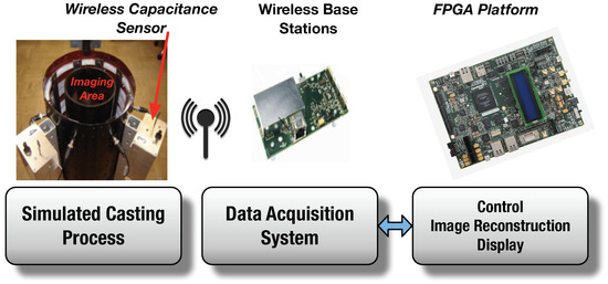
Figure 2.
Wireless electrical capacitance tomography system.
The casting process is simulated in the first stage where the capacitive sensors are mounted. The foam is represented by a pipe in the center of the flask and the metal will exist in this area. The collected measurements are relative to the metal distribution inside the imaging area [25,26]. In the second stage, there is a data acquisition system (base-station) collecting the data wirelessly from the sensors and working as a bridge between the sensing circuits and the FPGA platform. This base-station is connected to the controlling and monitoring FPGA station in the final stage where an image reconstruction algorithm is implemented. The base-station either collects packets from the ECT sensors or sends commands from the FPGA to that sensors. In our application, the Crossbow MIB600CA gateway is hooked to a MicaZ mote to function as the base station. There is a program on the mote to read the collected packets from the nodes and sends them to the gateway. The integration of main functional units on a single chip reduces the size and the cost of the proposed system.
3. Image Reconstruction Algorithm
An appropriate image reconstruction algorithm is applied to solve the inverse problem. The input of the inverse problem is the capacitance measurements while the result is a sequence of tomographic images describing the conductivity distribution inside the area of interest. Typically, a PC is used for implementing this algorithm where the data is processed and the final images are displayed. The relationship between the capacitance measurements (C) and the materials distribution (H) is highly nonlinear. However, this relation can be approximated as the following [14]:
where C is a vector of m normalized measurements related to a certain conductive distribution, vector H has n normalized pixel values indicating the metal distribution, and S a normalized matrix called sensitivity matrix. The values in H are either zero or one, where zero means no metal exists and one for metal. Each row in the sensitivity matrix represents how the capacitance measurements of each sensor change by altering each pixel from metal to no metal, therefore the S is also called a capacitance coefficient. In the case of six sensors, m equals 6, and the image is divided into pixels, so n is 256. The sensitivity matrix contains six sets of capacitance coefficients, and each one has 256 values related to each individual pixel in the image.
The discrete form of the image reconstruction algorithm computes H by using the values of C, while S is kept constant for simplicity [27]. One of the initial reconstruction algorithms is Linear Back Projection (LBP) which applies a transpose of the sensitivity matrix instead of its inverse to calculate grey levels of the image pixels. Thus, to calculate H, the transpose of S is multiplied by C:
Usually, applying LBP as a single step solution for the inverse problem creates blurred images since the problem is highly nonlinear. Therefore, to improve the quality of the reconstructed images, the inverse problem has to be solved iteratively. Typically, a modified version of the LBP algorithm that solves Equation (2) iteratively is common and called the Iterative Linear Back Projection (ILBP) algorithm [28]. The image vector is calculated as shown in Equation (3):
where vector contains the measured capacitance, is the solution of the forward problem, and k are the relaxation factor and the iteration number, respectively. Figure 3 presents a general nonlinear reconstruction algorithm. One of the most effective stages of the inverse problem is the solution of the forward problem which was applied in the iterative loop and significantly affects the speed and resolution of reconstructed images.
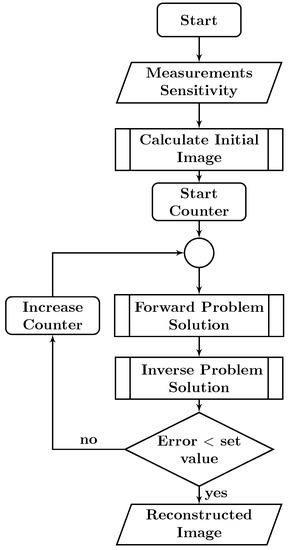
Figure 3.
Nonlinear reconstruction algorithm in ECT.
The ILBP algorithm can be summarized in the following steps:
- An initial image is obtained by the LBP algorithm Equation (2).
- The forward problem Equation (1) is solved to calculate a vector of capacitance measurements.
- Differences between the calculated and the actual measurements is multiplied by to calculate pixels’ errors.
- The difference between the previous image and the pixels’ errors represents the new image.
- The termination is reached when the difference in step 3 reaches a certain acceptable value.
Typically, these algorithms involve a large number of matrix operations, therefore implementing it on a parallel processing platform rather than a serial PC is crucial. For example, the ILBP algorithm implemented on a 2.53 GHz-i5 PC with 4 GB RAM generates a 32 × 32 image in more than 1.5 s.
4. Design Philosophy and Challenges
The ECT reconstruction algorithms are built on matrix multiplication. To enhance the performance of these algorithms, an efficient matrix multiplier is crucial. Commonly, there are two methods for implementing matrix multiplier, either fast processors or dedicated hardware. The implementation using the first one is slow and considered as a bottleneck in most applications. Therefore, the design of the matrix multiplier on the FPGA offers two main advantages, fast computation time and flexibility.
The FPGA platform contains all fundamental modules such as data acquiring and processing modules as well as all mathematical processing operations needed for the reconstructed algorithm. Furthermore, the FPGA design includes modules for communicating with I/O devices such as the Wireless Base Station (WBS) and the display module. Integrating all modules on one platform realizes a low cost and small size system. Moreover, the system will attain high robustness and fault tolerance since the FPGA resources are dynamically reconfigurable.
The System-on-Programming-Chip (SoPC) technology is applied in the proposed system. The Qsys is a powerful development tool usually used to build systems based on processors, peripherals, and memories. Utilizing the Qsys tool in defining and creating a complete system significantly reduces the design time compared to traditional and manual integration methods. A comprehensive integration between the hardware programming and software programming has been carried out in order to reduce the complexity of the system. Therefore, some complicated mathematical operations are implemented by a soft processor called the ARM processor defined in a hardware description language. This processor is implemented in Altera’s FPGA platform by using the Quartus CAD system. The software package required for building and configuring this software processor is Qsys.
There are design challenges that have to be identified before implementing the proposed system. First, studying the benefits and difficulties when dealing with a Real Time Operating System (RTOS). The RTOS can afford convenience since all of its drivers are included even they are not used in the current system. However, this occupies a lot of the available resources of the FPGA platform. Therefore, the RTOS is not deployed in the proposed system, which imposes a challenge of designing each desired driver on the chip while reducing the target chip size. Second, careful attention has to be paid to the synchronization between the designed VGA interface and both the processing unit and the memory. Lastly, applying the soft processor requires predefined libraries and modules while all the libraries and modules are designed and implemented in the proposed system since they are not existing in the embedded software.
5. System Implementation
The implementation process of the proposed system can be broken down into three steps: 1. Choosing and configuring of the hardware by the Qsys; 2. Writing the hardware description files using Quartus; 3. Functioning the software processor, after deploying the hardware files on the FPGA board, to be united with the program running on the FPGA. Therefore, the hardware and software implementation phases are crucial. In the hardware implementation phase, the following customized modules have to be designed: SDRAM memory, VGA peripheral, processing unit, and an Ethernet interface. All the hardware components are connected by an AX14 bus, whereas the software phase is the deployment of the image reconstruction algorithm on the embedded software ARM processor.
The FPGA platform has two inputs: the sensitivity matrix stored on the SDRAM and the capacitance measurements collected wirelessly and passed to the FPGA through the WBS [29]. The software processor is responsible for taking these two inputs and applies the ILBP algorithm to reconstruct distribution images. The VGA peripheral takes the final images to display it and store it on the SDRAM. The frequency of reading the SDRAM by the VGA controller is 25 MHz. The VGA controller and other hardware components are coded using HDL while the code of the ILBP algorithm is implemented by embedded C language. The proposed system is shown as a block diagram in Figure 4.
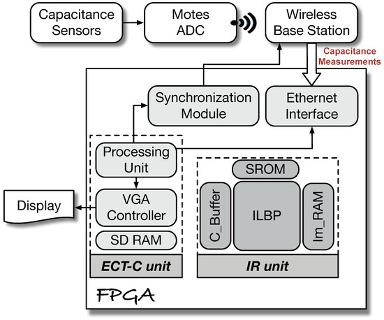
Figure 4.
Block diagram of the proposed system.
The HDL Workflow Advisor of the HDL Coder is used in our work for simulation and synthesis. The synthesis process is generating a netlist as an HDL file that is used by the software processor. The design has to be tested and verified before the synthesis process. After the verification of the final design, a binary file holding all information for configuring the FPGA board will be generated. Furthermore, the Qsys generates files which are used by the Quartus, while the Quartus writes the responsible top-level module to begin the desired task and calling other modules.
5.1. FPGA Platform and Software Tools
The implementation of the ECT system is carried out on an Altera Cyclone V SoC FPGA platform. This platform has the Cyclone V 5CSXFC6D6F31C6 Revision D FPGA device, DDR3 memory, and common interface controllers. A multicore ARM processor subsystem is integrated into the FPGA fabric, in addition to a Hard Processing System (HPS) has a dual-core ARM Cortex-A9 MPCore processor running at 925 MHz frequency. A standard AXI4 bridge connects the HPS to the FPGA fabric, which provides communication means between masters on the FPGA fabric and slaves in the HPS logic. The Matlab HDL Coder [30] integrated with the Altera suite of development tools, Quartus II, and the SoC Embedded Design Suite (EDS) are the tools used in the implementation of the proposed system [31].
Currently, the embedded system design is applied on the system-level rather than the RTL-level in order to reduce difficulties associated with the RTL-level design and benefit from the immediate integration between the HW/SW in the system design phase. Therefore, sophisticated embedded SoC design tools such as Altera Qsys integrated to its Quartus II CAD system have been developed. These tools integrate components such as the processor, DSPs, FPGA IPs, and I/O peripherals on the FPGA platform. In addition, other tools such as SoC Embedded Design Suite (SoC EDS) help in the software design on the ARM processor [31]. However, there are some difficulties when working with these tools such as having two separate workflows. The hardware workflow is implemented using Quartus II CAD tool integrated with the HDL language for modeling custom hardware IPs, whereas the software workflow is managed by the SoC EDS toolset.
The HDL Coder and Embedded Coder from Mathworks are Model-Based design workflow toolboxes. These two tools generate synthesizable HDL code and Embedded C code, respectively, from MATLAB code as well as from Simulink model. Therefore, the HDL coder integrated with the Altera Quartus II can generate an optimized hardware IP targeting the Cyclone V SoC FPGA device that can be integrated with a larger design using Qsys tool as well as generating the design bitstream file ready to be downloaded to the FPGA fabric. Similarly, linking with Altera SoC EDS allows the Embedded Coder to generate an executable “.elf” file downloadable to the ARM processor on the FPGA platform.
5.2. System Architecture
The architecture of the ECT system consists of two main compounds: an ECT controller (ECT-C) and an Image Reconstruction (IR) unit as shown in Figure 4. The ECT-C unit is connected to two parts outside the FPGA platform, a Wireless Base Station (WBS) and an LCD peripheral. In addition, the IR unit itself has three elements, which are a matrix processing block, memory and buffering blocks, as well as an Image RAM (Im_RAM) block. The matrix processing block realizes the implementation of the three steps of Equation (3), while the memory blocks work as a storage for the capacitance measurements in a C_Buffer, and the constant sensitivity matrix in a S_ROM block. The last Im_RAM block stores the pixels values of the reconstructed image.
5.3. Matrix-Vector Multiplication Scheme
The crucial computation model of the image reconstruction algorithms Equations (2) and (3) consists of Matrix-Vector Multiplication, MVM; while the core unit of the MVM entails inner-product. A large MVM requires an efficient design and implementation of the FPGA hardware architecture to achieve the real-time performance requirements. The MVM is implemented by multiplying rows of matrix G by the corresponding column elements of vector C. The operations of the MVM are:
- Reading row elements of matrix G and column elements of vector C,
- Storing these elements in internal buffers,
- Multiplying row and column elements,
- Adding the multiplier output and storing the results in the output buffers.
Each stage of the MVM is built using a shared segmented parallel inner-product architecture to attain the trade-off between the high performance and the limited resources of the FPGA. The parallel implementation of the MVM realizes higher performance within a single computation cycle than serial implementation, but requires huge FPGA resources; multiplier and adders. Therefore, implementing the MVM using a shared parallel inner-product architecture can fulfill the performance/resource-usage trade-off.
Building a parallel inner-product architecture by applying parallel multiplication operations of the inner-product procedure will enhance the performance against the cost of increasing the required resources. Realization of the inner-product of two N vectors in a single computation cycle requires N multiplier and adders. The parallel multiplication of all pairs of elements of the inner-product input vectors then adding them to produce the final result reduces the combinational path delay.
Segmentation of the inner-product to multiple segments reduces the combinational paths delay for large vectors and lower the number of resources. Every computational cycle, only one segment from both input vectors enters the segmented inner-product unit. The combinational path delay consists of multiple clock-cycles via a delay-counter which enables writing the partial inner-product to a memory buffer at the end of the computation cycle.
In the model-based design at the system-level, the segment length is an input to the design flow which greatly minimizes the development time and effort and relieves remodeling the system in each design cycle. The first LBP matrix-vector multiplication stage of the iLBP algorithm is organized as to feed each row vector of matrix as well as the C vector to the segmented inner-product unit.
5.4. Hardware–Software Partitioning
The main advantages of the embedded system design are performance and flexibility. Although the software implementation has high flexibility with low design efforts, its performance gain is low. Instead, the intrinsic parallelism of the hardware attains high system performance, but its design is complex. Therefore, in the embedded system design, the Hardware–Software (HW/SW) codesign manages the trade-off between the reasonable performance and flexibility.
The partitioning of the hardware and software components is a crucial stage in the HW/SW codesign of the SoC system. The analysis of the system states that the ILBP algorithm which has continually intensive matrix computation is a feasible candidate for the hardware implementation on the FPGA fabric, while the ECT-C unit is a control flow-intensive state machine which interfaces with the WBS and the LCD. Therefore, the ECT-C unit is suitable for the software implementation on the ARM processor of the FPGA platform, which reduces the required software drivers for these peripherals.
The SoC design and implementation of the proposed ECT system, the IR unit, and the ECT-C have been carried out in two stages. In the first stage, the Matlab Hardware-Software Codesign Workflow is applied to generate an HDL IP for the IR algorithm and a C code for the software ECT-C unit. In the second stage, the generated HDL IP is joined the Altera Qsys with the ARM processor and the other system blocks such as SDRAM, LCD driver, and WBS to build the final ECT system. The generated C code for the ECT-C unit is integrated with the rest of the software components in the Altera SoC EDS toolset for debugging and performance measure.
The Matlab HW/SW codesign workflow of the IR unit is implemented into two steps: First, a Matlab model for the ECT system is built, then it is converted to a fixed-point version; afterwards, its equivalent Simulink model is built. The created Simulink model of the proposed ECT system has the partitioned HW part (IR algorithm) and the SW part (ECT-C).
5.5. Hardware Implementation
In order to increase the performance gain, energy efficiency, and fewer hardware resources, the IR algorithm is realized with the fixed-point representation, where the word length is chosen to be 32-bits in the simulation to preserve similar precision of its floating-point counterpart. Inside the Simulink model and by utilizing the HDL Workflow Advisor tool of the HDL coder, we have generated the HDL IP core for the IR unit, and the interface logic to the software part mapped to the ARM processor. Typically, the IP interface logic is abstracted as a software interface model with the AXI4 interface to the ARM processor.
The design involves a computation of image H using , where is a matrix of size , vector C has size and the size of matrix H is . It is essential to develop a library of arithmetic matrix operations such as transpose, multiplication, and subtraction. Using HDL Workflow Advisor tool of the HDL Coder toolbox, the HDL-code as an IP-core for the image reconstruction subsystem is generated. In the same process, the IP interface logic as well as its abstract software interface model to the ARM processor is automatically generated according to the AX14 interface.
The iteration loop is controlled either by the iterations number or a predefined error. The number of iterations controls the quality and accuracy of the reconstructed images. Hence, the optimal number of iterations has to be carefully chosen. There is a trade-off between increasing the iteration number to enhance the accuracy and computational time, especially for dynamic applications. Another way to stop the iteration loop is reaching the difference between the actual and estimated measurements a predefined value E. Figure 5 shows the execution of the ILBP algorithm on the software processor.
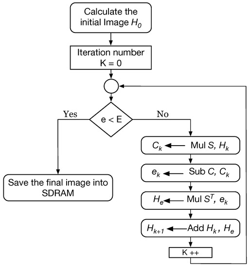
Figure 5.
Flow chart of the ILBP algorithm.
The memory interfaces play a vital role in the design of the ECT system. The Altera FPGA internal RAM memory blocks are used as the system’s memory. The word size of the memory block is set to be 256 (16-bit). During the communication process between the processor and the memory, the memory read/write operations are issued by the processor controller. These operations allow reading and storing the transferred information and intermediate results from and to the memory. In addition, the interface of the memory has logic for the generation of various memory control signals.
In order to boost the code of signal processing, a fixed-point matrix arithmetic library containing basic operations such as an adder, subtractors, and multipliers is implemented. Arithmetic modules of 8, 16, and 32 bits were developed using HDL to adapt the requirements of the reconstruction algorithm. The bitmaps created from these modules were effectively verified after downloading it the FPGA platform. Conclusively, the functions’ flow diagrams were translated into HDL code. Functional calls representing the arithmetic operations are established to decrease the number of arithmetic unit instantiations.
5.6. Software Implementation
The software phase of the design containing the ECT-C unit attached to the generated AX14 interface model is implemented by the Embedded Coder and a code is generated. Finally, the generated HDL IP code for the IR unit is integrated into the proposed ECT system by utilizing Qsys tools in Quartus II CAD system. Moreover, the generated C code of the ECT-C is ready to be integrated with the other software components of the ECT system.
On the other hand, the generation of the ECT-C corresponding C code for the ARM processor is handled by the Embedded Coder toolbox so as to be connected to the generated AX14 interface model. The compiled and bit-stream configuration files of the generated C and HDL-code parts, respectively, of the system, can be deployed to the FPGA platform directly from within the HDL Workflow Advisor tool. The generated C code the rest of the software components will be integrated into the final ECT system. Using the Qsys tools of the Quartus II CAD system, the generated HDL IP core for the image reconstruction subsystem can be reused within other related ECT systems.
The VGA peripheral has two functions, controlling the VGA and reading/writing the SDRAM. The VGA peripheral controls the SDRAM beside communicating with the software processor and accepting data from it. Initially, the IDE processor sends a one-pixel image as a header to the VGA controller. This image alerts the peripheral that a new image needs to be written on the SDRAM since it is defined that there is no image with width 1. At this time, the display will be blanked out so the user will not notice the writing process on the SDRAM. In addition, a flag is set to signify the change of the background “complexion” is needed. The background color is chosen as white to match the picture. Afterwards, the address where the image will be written in the SDRAM is introduced by the software processor. The controller will keep sending the SDRAM addresses followed by SDRAM until the entire image is displayed.
6. Experimental Setup and Results
Our ECT system consists of six capacitance sensors evenly distributed around a rectangular foam pattern centered in circular flask a shown in Figure 1. The rectangular imaging area is where the metal will exist. The mutual capacitance between the electrodes corresponding to each metal distribution were wirelessly collected. The Finite Element Method (FEM) is applied to create a mesh consisting of 720 linear triangular elements inside the flask. The image area of size 16 × 16 pixel is meshed in the center of the FEM model to reduce the complexity of the computation. Therefore, the sensitivity matrix S of size 6 × 256 and a measurement electrodes capacitance C vector of size 6 elements were applied during the experiments. Since the solution of the forward problem requires solving nonlinear differential equations and it happens once, it is faster to calculate it using Matlab on a PC. The sensitivity matrix is calculated by FEM and saved on the SDRAM. Simulink modules representing the proposed system are developed for testing and verification purposes. The HDL Workflow Advisor generates the bitstream file which is downloaded on the FPGA fabric through the JTAG USB interface. The mathematical matrix operations library coded in C is compiled and built to an executable file. The generated file is deployed to the ARM processor in the Altera Qsys FPGA platform.
The image reconstruction subsystem of the ECT system is coded with HDL-synthesizable; while the main processing unit is modeled with C-compatible. The system-level simulation of the cycle-accurate model allows functional verification as well as cycle-based performance measurement.
The ILBP reconstruction algorithm implemented on the FPGA platform is applied to generate the final tomographic images. In order to test the performance of the developed system, different distributions of metal pieces inside the imaging area are used. Figure 6 illustrates the actual metal distributions in the first column, while the results of the reconstructed images are shown in the second column. Two metal pieces shown in Figure 6a are positioned in front of sensor and simultaneously. The reconstructed image shown in Figure 6b proves how the proposed system is able to identify the position of the two pieces correctly. Another metal distribution of three metals located in front of sensors , , and is shown in Figure 6c, while the result in Figure 6d from the algorithm deployed on the FPGA accurately detected the locations of the three pieces.
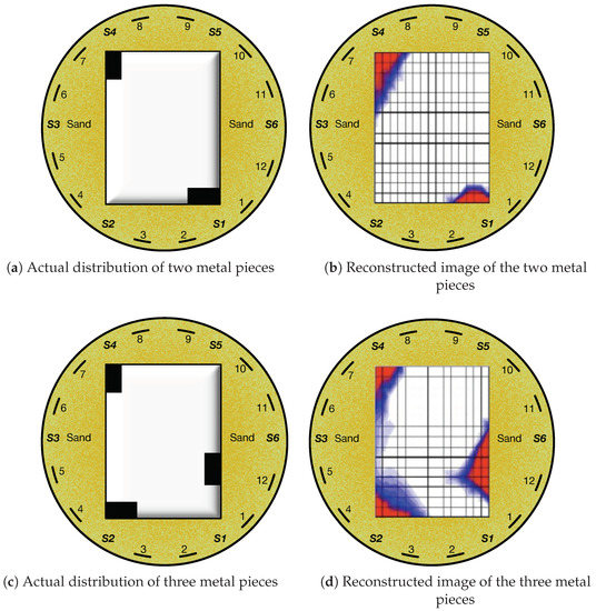
Figure 6.
Actual metal distribution and reconstructed tomographic images for different metal objects using an ILBP algorithm.
Regarding the FPGA (Altera Cyclone V) resources, about 11% of the total logic elements is used on the integrated prototype and only 15% of its memory. The maximum propagation delay captured for the system is 12.04 ns lesser than the 50 MHz clock period of 20 ns. The power consumption of the Cyclone-V FPGA is low about 12 mW.
7. Conclusions
In this paper, the ECT system is realized and deployed on FPGA architecture. In addition, hardware–software (HW/SW) codesign of the ECT digital processing unit is proposed. The solution of the inverse problem, Iterative Linear Back Projection (ILBP), is implemented on the FPGA to reconstruct the final metal distributions. The design and implementation of the ECT system via FPGA has greatly minimized the development time and reduces the design cycle as well as alleviates remodeling the system in each design cycle. A big improvement has been achieved by utilizing the reconfigurable platform compared to the PC. The new system has small size, high speed as well as low cost. The new architecture was evaluated on the FPGA running at a clock frequency of 50 MHz using Cyclone V. The results have showed that the proposed system just used only about 11% of the FPGA logic gates and 15% of its memory; also the speed has almost been doubled. The results showed that the proposed reconfigurable system is promising.
Funding
This work was supported by the Deanship of Scientific Research at Umm Al-Qura University, Grant No. 43308004.
Acknowledgments
The author would like to thank the Deanship of Scientific Research at Umm Al-Qura University for the financial support (Project No.: 43308004).
Conflicts of Interest
The authors declare no conflict of interest.
Abbreviations
The following abbreviations are used in this manuscript:
| AB | Avalon Bus |
| ARM | Advanced RISC Machines |
| ECT | Electrical Capacitance Tomography |
| EIT | Electrical Impedance Tomography |
| FPGA | Field Programmable Gate Array |
| FSM | Finite State Machine |
| FEM | Finite Element Method |
| GPU | Graphics Processing Units |
| HW/SW | Hardware/Software |
| ILBP | Iterative Linear Back Projection |
| JTAG | Joint Test Action Group |
| LBP | Linear Back Projection |
| LCD | Liquid Crystal Display |
| LFC | Lost Foam Casting |
| RTOS | Real Time Operating System |
| SDRAM | Synchronous Dynamic Random Access Memory |
| SoC | System-On-Chip |
| VGA | Video Graphic Array |
| VLSI | Very-large-scale integration |
| WSN | Sensor Networks |
References
- Kryszyn, J.; Wróblewski, P.; Stosio, M.; Wanta, D.; Olszewski, T.; Smolik, W.T. Architecture of EVT4 data acquisition system for electrical capacitance tomography. Measurement 2017, 101, 28–39. [Google Scholar] [CrossRef]
- Rahman, N.A.; Abdul Rahim, R.; Mohd Nawi, A.; Pei Ling, L.; Pusppanathan, J.; Mohamad, E.J.; Kok Seong, C.; Mohammad Din, S.; Nor Ayob, N.M.; Mohd Yunus, F.R.; et al. A Review on Electrical Capacitance Tomography Sensor Development. J. Teknol. 2015, 73, 35–41. [Google Scholar] [CrossRef]
- Woo, E.J.; Seo, J.K. Magnetic resonance electrical impedance tomography (MREIT) for high-resolution conductivity imaging. Physiol. Meas. 2008, 29. [Google Scholar] [CrossRef] [PubMed]
- Yao, J.; Takei, M. Application of Process Tomography to Multiphase Flow Measurement in Industrial and Biomedical Fields: A Review. IEEE Sens. J. 2017, 17, 8196–8205. [Google Scholar] [CrossRef]
- Soleimani, M. Numerical Modelling and Analysis of the Forward and Inverse Problems in Electrical Capacitance Tomography. Int. J. Inf. Syst. Sci. 2005, 1, 193–207. [Google Scholar]
- Meribout, M.; Saied, I.M. Real-time Two Dimensional Imaging of Solid Contaminants in Gas Pipelines using An Electrical Capacitance Tomography System. IEEE Trans. Ind. Electron. 2017, 64, 3989–3996. [Google Scholar] [CrossRef]
- Abd Rashid, W.N.; Mohamad, E.J.; Abdul Rahim, R.; Abdullah, J.; Mohmad Ameran, H.L. Electrical capacitance tomography: A review on portable ECT system and hardware design. Sens. Rev. 2016, 36, 64–70. [Google Scholar] [CrossRef]
- Deabes, W.A.; Abdelrahman, M.A. A nonlinear fuzzy assisted image reconstruction algorithm for electrical capacitance tomography. ISA Trans. 2010, 49, 10–18. [Google Scholar] [CrossRef]
- Abdelrahman, M.; Gupta, A.; Deabes, W. A feature-based solution to forward problem in electrical capacitance tomography of conductive materials. IEEE Trans. Instrum. Meas. 2011, 60, 430–441. [Google Scholar] [CrossRef]
- Wondrak, T.; Soleimani, M. A novel metal flow imaging using electrical capacitance tomography. Meas. Sci. Technol. 2017, 28, 064001. [Google Scholar] [CrossRef]
- Liu, X.; Wang, X.; Hu, H.; Li, L.; Yang, X. An extreme learning machine combined with Landweber iteration algorithm for the inverse problem of electrical capacitance tomography. Flow Meas. Instrum. 2015, 45, 348–356. [Google Scholar] [CrossRef]
- Castillo, E.; Morales, D.P.; Martinez-Olmos, A.; Alvarez, D.; Parrilla, L.; Palma, A.J.; Navello, F. Parametrized ECT processing over FPGA for a reconfigurable application. In Proceedings of the 2015 Conference on Design of Circuits and Integrated Systems (DCIS), Estoril, Portugal, 25–27 November 2016. [Google Scholar] [CrossRef]
- Deabes, W.A.; Abdelrahman, M.A.; Rajan, P.K. A New Wide Frequency Band Capacitance Transducer with Application to Measuring Metal Fill Time. Sens. Transducers 2009, 100, 72–84. [Google Scholar]
- Yang, W.Q.; Peng, L. Image reconstruction algorithms for electrical capacitance tomography. Meas. Sci. Technol. 2003, 14, R1–R13. [Google Scholar] [CrossRef]
- Morales, D.P.; Lopez-Ruiz, N.; Castillo, E.; Garcia, A.; Martinez-Olmos, A. Adaptative ECT system based on reconfigurable electronics. Measurement 2015, 74, 238–245. [Google Scholar] [CrossRef]
- Sohal, H.; Wi, H.; McEwan, A.L.; Woo, E.J.; Oh, T.I. Electrical impedance imaging system using FPGAs for flexibility and interoperability. Biomed. Eng. Online 2014, 13, 126. [Google Scholar] [CrossRef]
- Cui, Z.; Wang, H.; Yin, W. Electrical Capacitance Tomography With Differential Sensor. IEEE Sens. J. 2015, 15, 5087–5094. [Google Scholar] [CrossRef]
- Kim, J.K.; Fessler, J.A.; Zhang, Z. Forward-Projection Architecture for Fast Iterative Image Reconstruction in X-ray CT. IEEE Trans. Signal Process. 2012, 60, 5508–5518. [Google Scholar] [CrossRef]
- Fysikopoulos, E.; Georgiou, M.; Efthimiou, N.; David, S.; Loudos, G.; Matsopoulos, G. Fully digital FPGA-based data acquisition system for dual head PET detectors. IEEE Trans. Nucl. Sci. 2014, 61, 2764–2770. [Google Scholar] [CrossRef]
- Xu, L.; Taufer, M.; Collins, S.; Vlachos, D.G. Parallelization of tau-leap coarse-grained Monte Carlo Simulations on GPUs. In Proceedings of the IEEE International Symposium on Parallel and Distributed Processing (IPDPS), Atlanta, GA, USA, 19–23 April 2010. [Google Scholar] [CrossRef]
- Kapusta, P.; Majchrowicz, M.; Sankowski, D.; Jackowska-Strumiłło, L. Acceleration of image reconstruction in 3D Electrical Capacitance Tomography in heterogeneous, multi-GPU system using sparse matrix computations and Finite Element Method. In Proceedings of the Federated Conference on Computer Science and Information Systems, Gdansk, Poland, 11–14 September 2016; pp. 679–683. [Google Scholar] [CrossRef]
- Amira, A.; Bouridane, A.; Milligan, P.; Sage, P. A high throughput FPGA implementation of a bit-level matrix product. In Proceedings of the IEEE Workshop on Signal Processing Systems (SiPS), Lafayette, LA, USA, 11–13 October 2000; pp. 356–364. [Google Scholar] [CrossRef]
- Belkacemi, S.; Benkrid, K.; Crookes, D.; Benkrid, A. Design and implementation of a high performance matrix multiplier core for Xilinx Virtex FPGAs. In Proceedings of the IEEE International Workshop on Computer Architecture for Machine Perception (CAMP), New Orleans, LA, USA, 12–16 May 2003; pp. 156–159. [Google Scholar] [CrossRef]
- Saied, I.; Meribout, M. Electronic hardware design of electrical capacitance tomography systems. Philos. Trans. R. Soc. A 2016, 374, 3–31. [Google Scholar] [CrossRef]
- Al Hosani, E.; Zhang, M.; Soleimani, M. A limited region electrical capacitance tomography for detection of deposits in pipelines. IEEE Sens. J. 2015, 15, 6089–6099. [Google Scholar] [CrossRef]
- Deabes, W.A.; Amin, H.H.; Abdelrahman, M. Optimized fuzzy image reconstruction algorithm for ect systems. In Proceedings of the EEE International Conference on Fuzzy Systems (FUZZ-IEEE), Vancouver, BC, Canada, 24–29 July 2016; pp. 1209–1215. [Google Scholar] [CrossRef]
- Mishra, A.; Yadav, H.; Rani, S.; Design, M.T.V. A Review of Different Methods for Matrix Multiplication Based on FPGA. Int. J. VLSI Embed. Syst. 2014, 5, 747–751. [Google Scholar]
- Alme, K.; Mylvaganam, S. Electrical Capacitance Tomography–Sensor Models, Design, Simulations, and Experimental Verification. IEEE Sens. J. 2006, 6, 1256–1266. [Google Scholar] [CrossRef]
- Deabes, W.; Abdallah, M.; Elkeelany, O.; Abdelrahman, M. Reconfigurable wireless stand-alone platform for Electrical Capacitance Tomography. In Proceedings of the IEEE Symposium on Computational Intelligence in Control and Automation, Nashville, TN, USA, 30 March–2 April 2009; pp. 112–116. [Google Scholar] [CrossRef]
- MATLAB. Global Optimization Toolbox. 2017. Available online: https://www.mathworks.com/products/global-optimization.html (accessed on 15 June 2018).
- Altera. Cyclone V Hard Processor System Technical Reference Manual; Technical Report; Altera: San Jose, CA, USA, 2016. [Google Scholar]


© 2019 by the author. Licensee MDPI, Basel, Switzerland. This article is an open access article distributed under the terms and conditions of the Creative Commons Attribution (CC BY) license (http://creativecommons.org/licenses/by/4.0/).