Nonlinear Modeling and Coordinate Optimization of a Semi-Active Energy Regenerative Suspension with an Electro-Hydraulic Actuator

Abstract
:1. Introduction
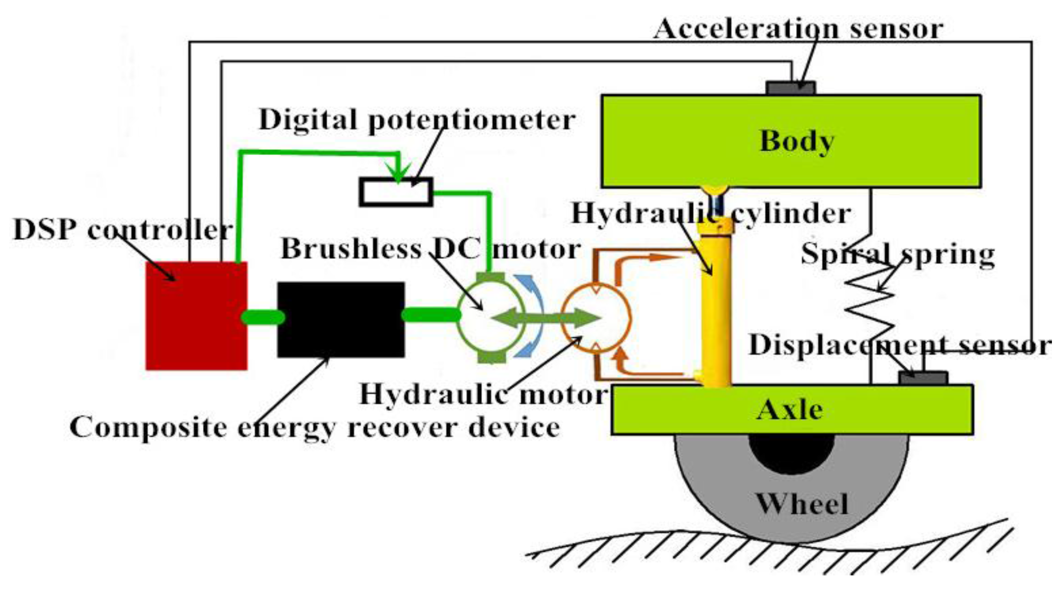
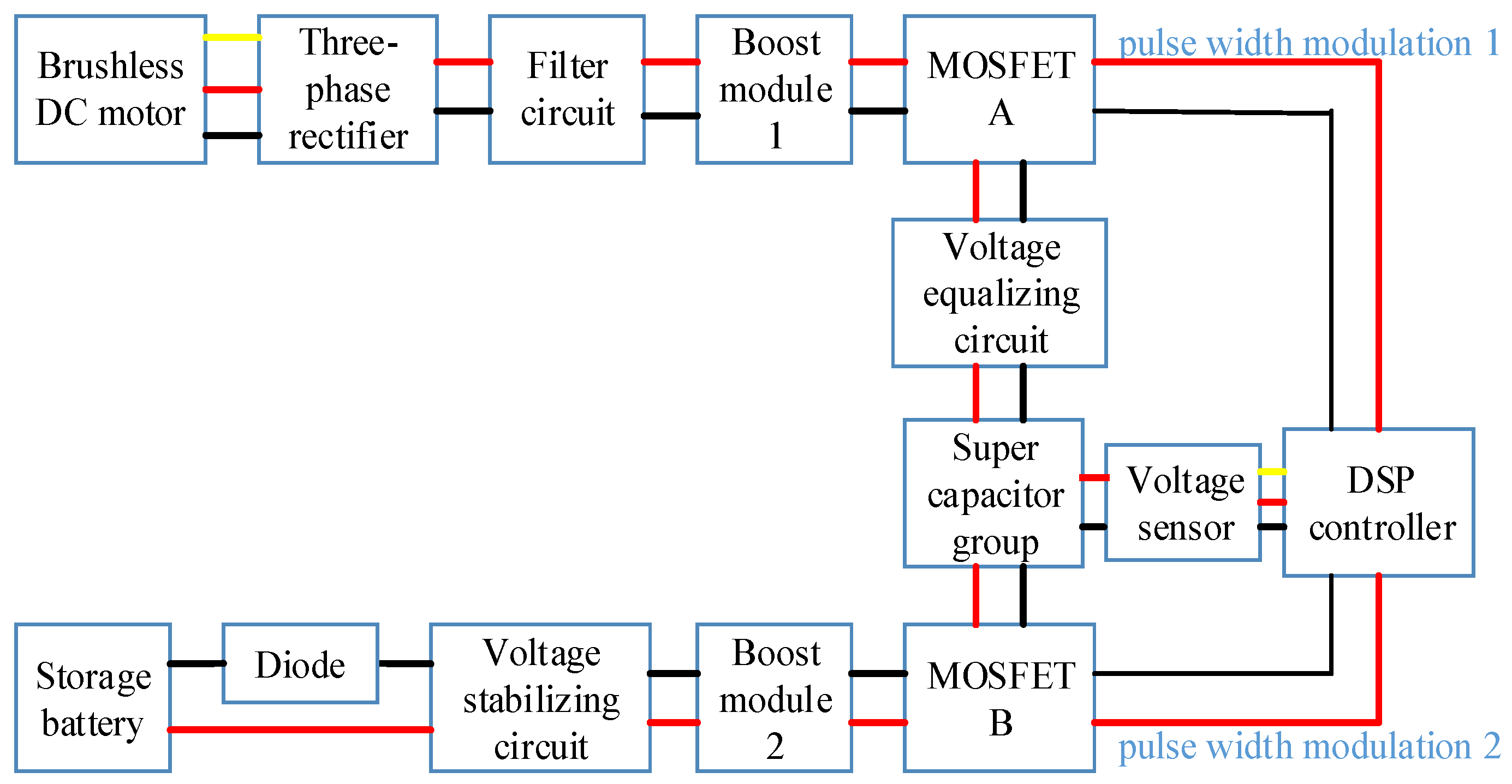
2. Structure and Principle of the Semi-Active Energy Regenerative Suspension with an EHA
3. Nonlinear Modeling of the Semi-Active Energy Regenerative Suspension with an EHA
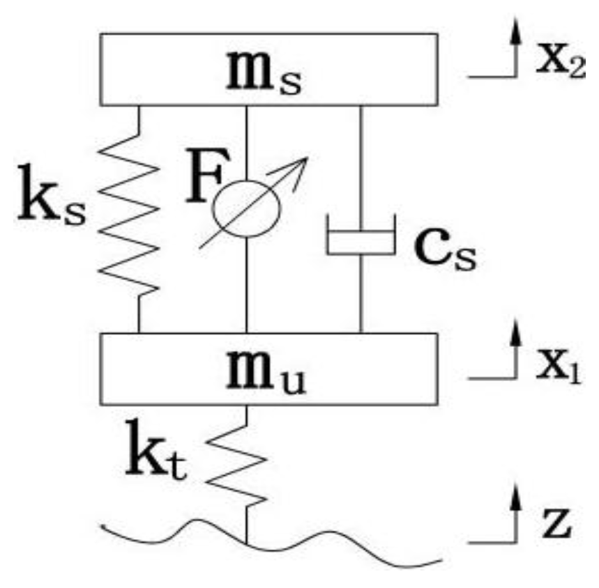
3.1. Dynamic Model of a Two Degrees of Freedom Suspension System for a Quarter-Vehicle
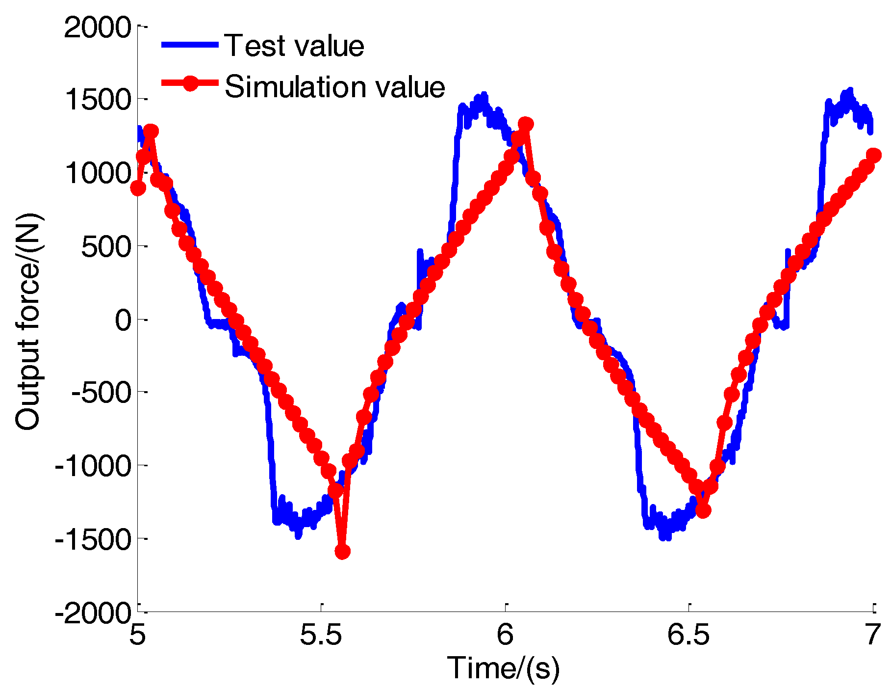
3.2. Parameter Identification of Nonlinear Model
3.3. Mathematical Model of the Semi-Active Energy Regenerative Suspension with an EHA
4. The Control Strategy of the Semi-Active Energy Regenerative Suspension with an EHA
5. Parameter Optimization of the Semi-Active Energy Regenerative Suspension with an EHA
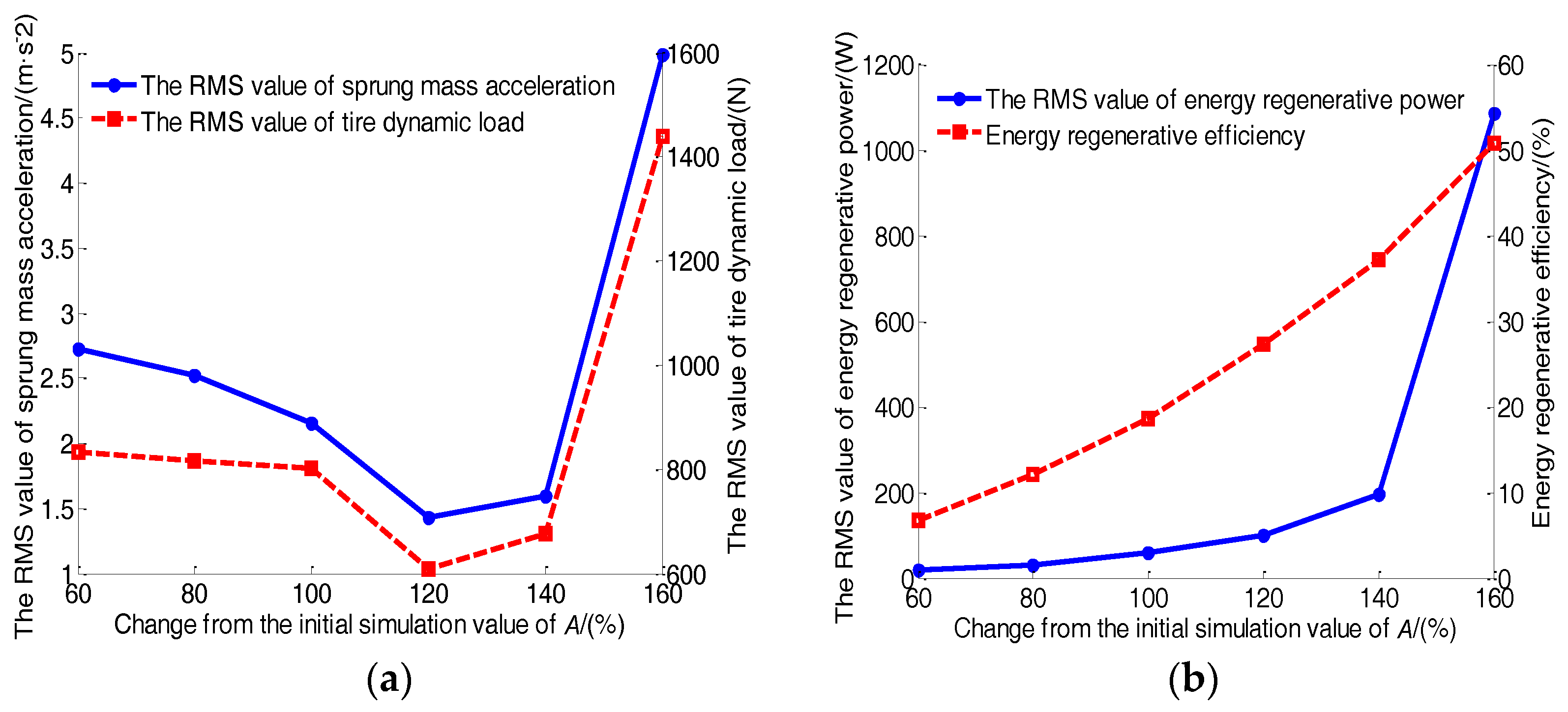
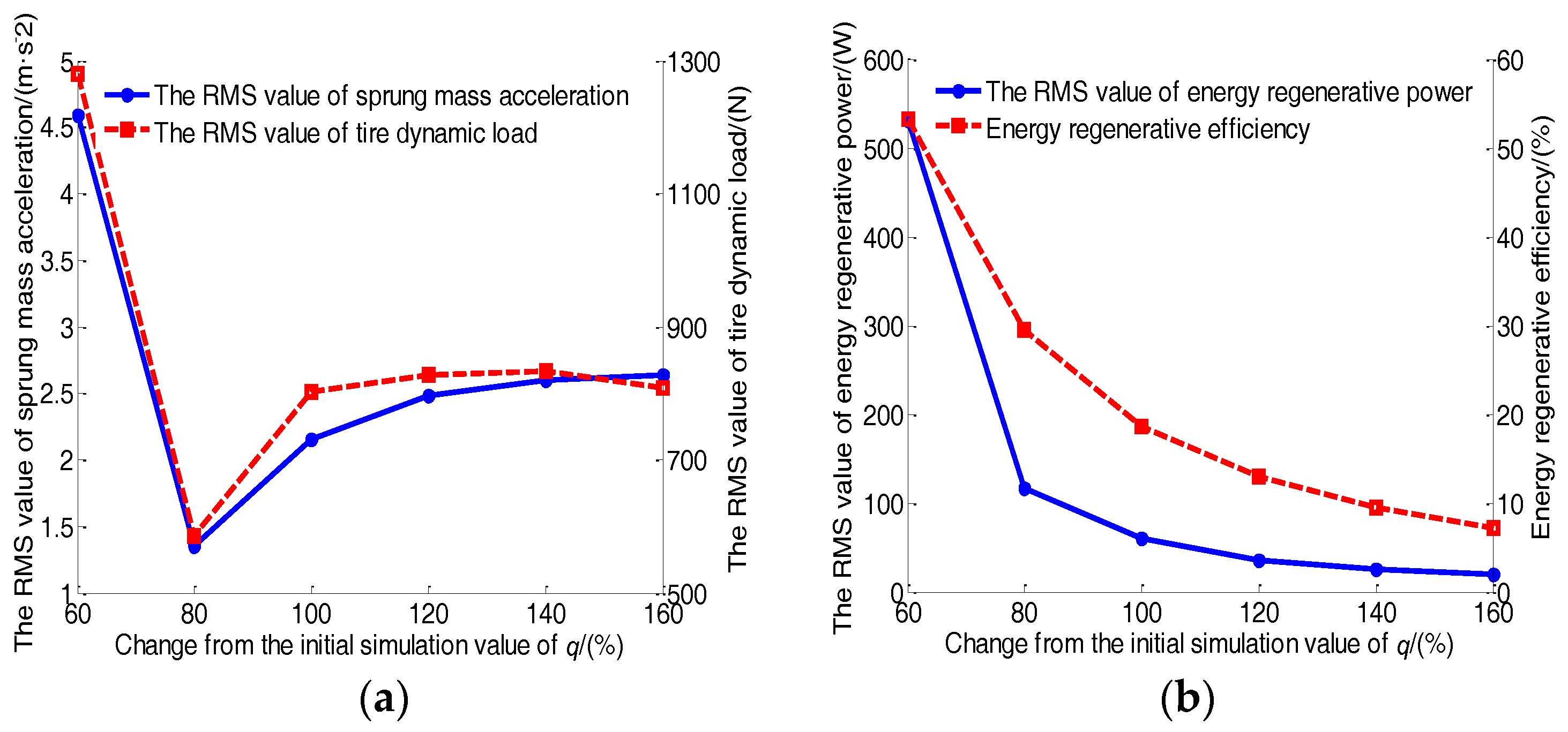
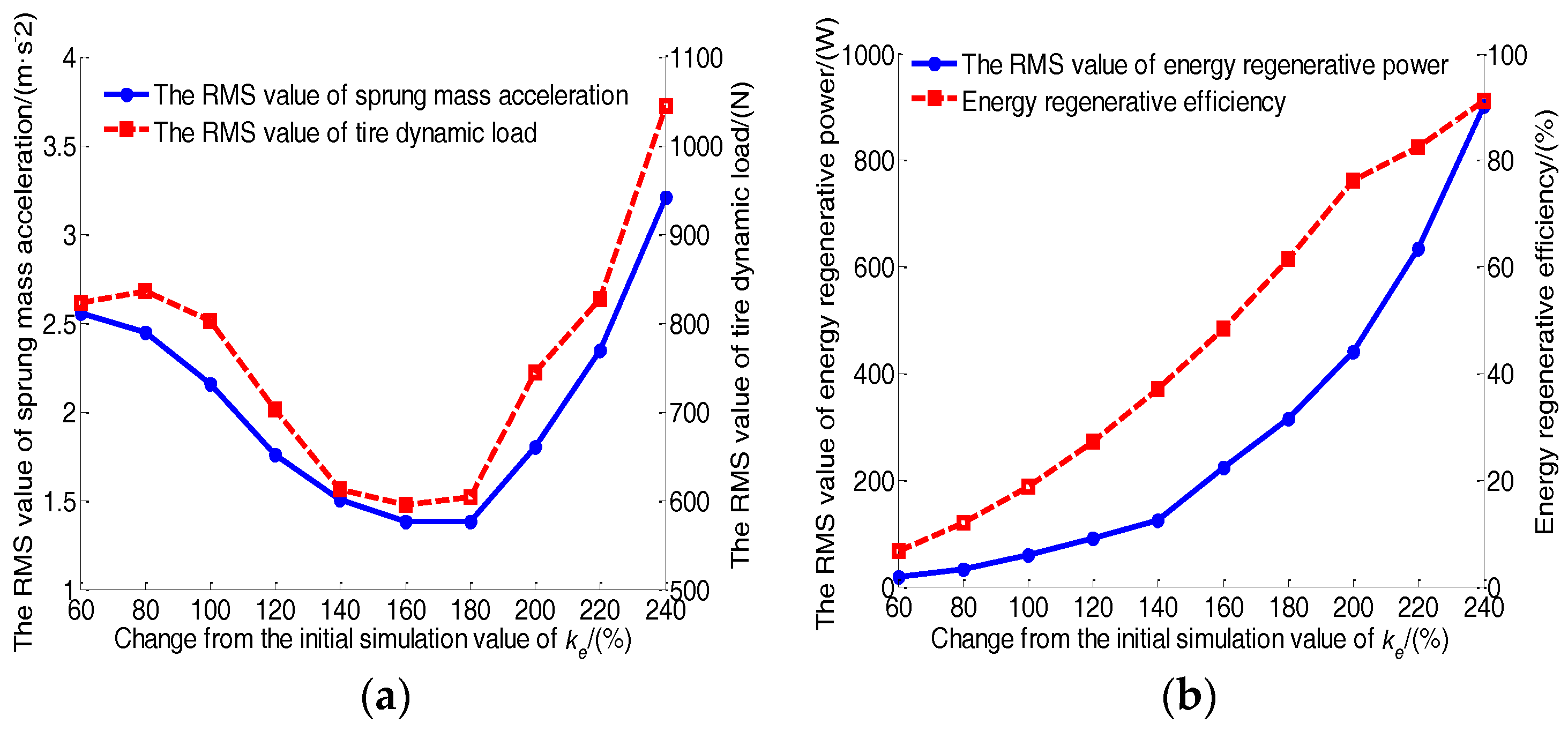
5.1. Parameter Sensitivity Analysis
5.2. Optimization Objectives and Constraints
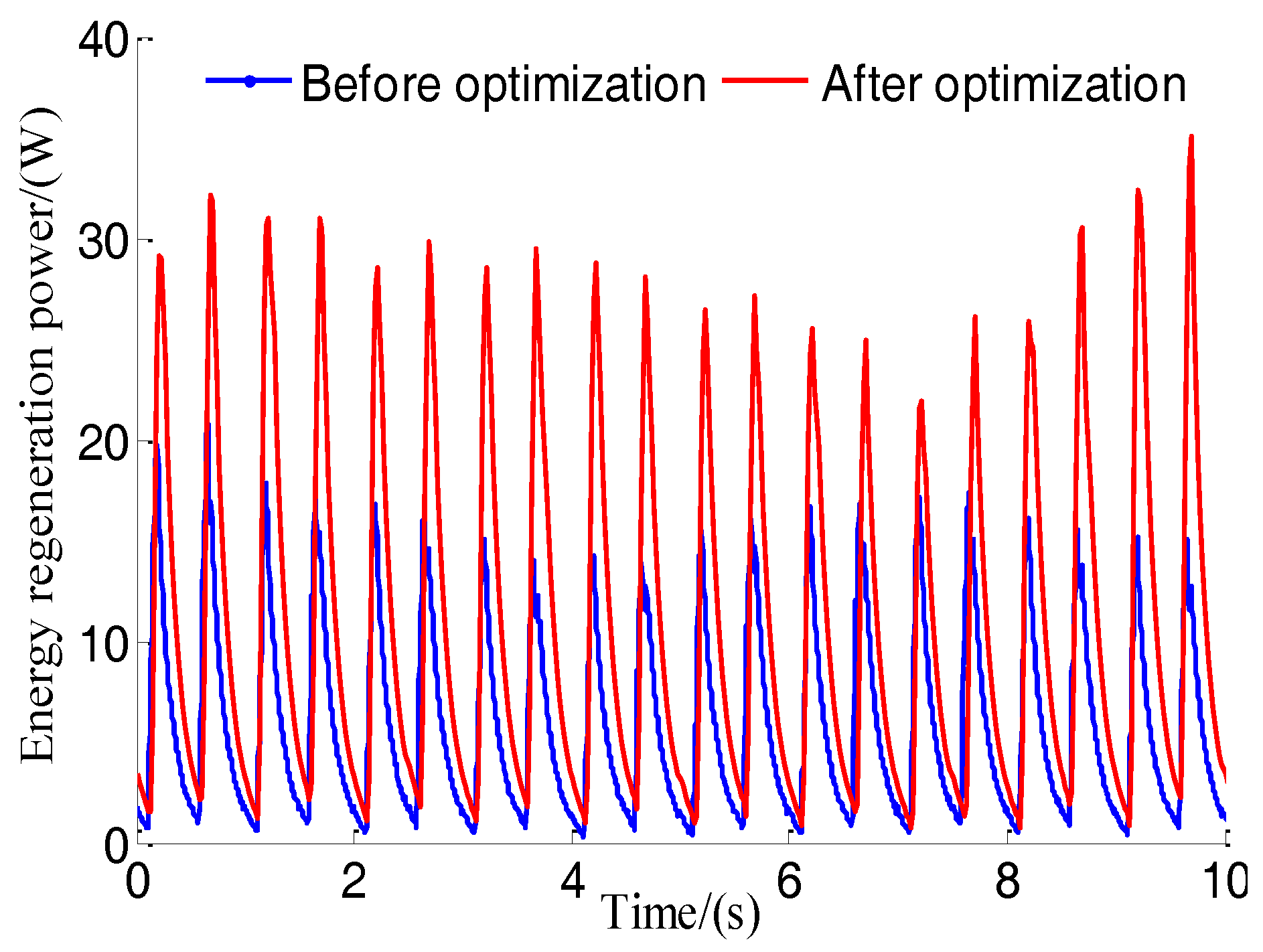
5.3. Optimization Result Analysis
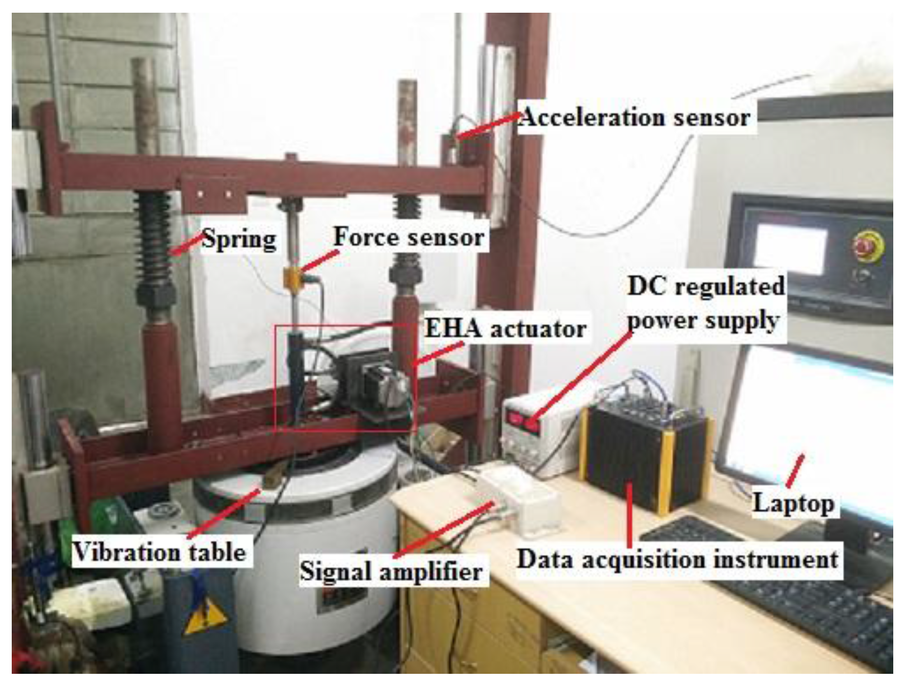
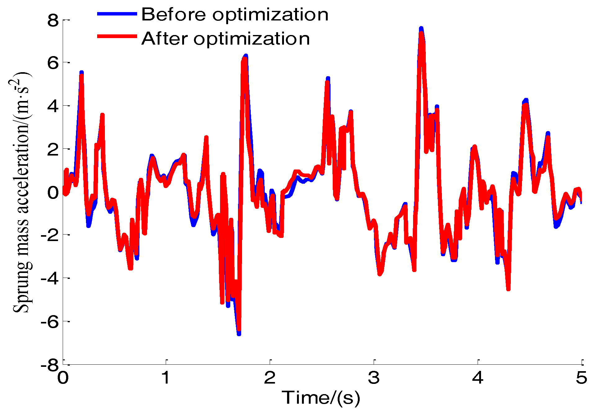
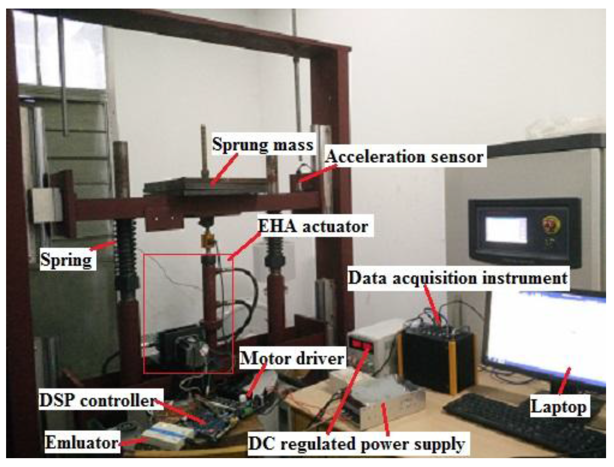
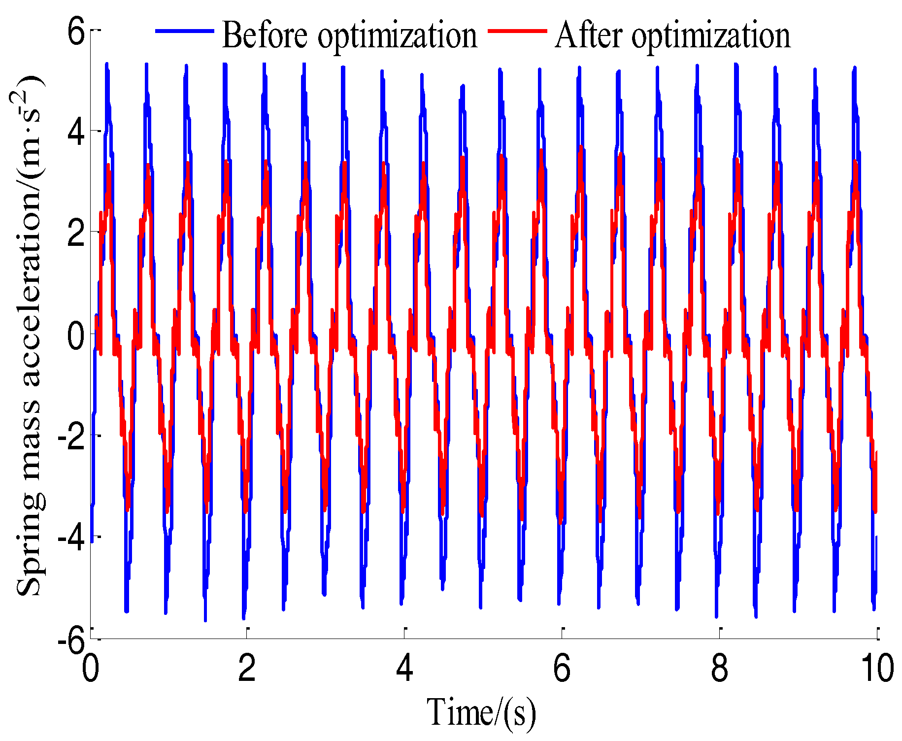
5.4. Test and Analysis
6. Conclusions
Acknowledgments
Author Contributions
Conflicts of Interest
References
- Tseng, H.E.; Hrovat, D. State of the art survey: Active and semi-active suspension control. Veh. Syst. Dyn. 2015, 53, 1034–1062. [Google Scholar] [CrossRef]
- Chen, S.A.; Li, X.; Zhao, L.J. Development of a control method for an electromagnetic semi-active suspension reclaiming energy with varying charge voltage in steps. Int. J. Automot. Technol. 2015, 16, 765–773. [Google Scholar] [CrossRef]
- Wu, L.N.; Shi, M.M.; Wang, R.C. Parameter optimization of hybrid suspension with linear motor based on PSO. J. Chongqing Univ. Technol. (Nat. Sci.) 2016, 30, 12–17. [Google Scholar]
- Babak, E. Development of Hybrid Electromagnetic Dampers for Vehicle Suspension Systems; University of Waterloo: Waterloo, ON, Canada, 2009. [Google Scholar]
- Okada, Y.; Ozawa, K. Energy Regenerative and Active Control of Electro-Dynamic Vibration Damper. Trans. Jpn. Soc. Mech. Eng. C 2005, 70, 233–242. [Google Scholar]
- Zhang, H.; Guo, X.X.; Hu, S.B.; Fang, Z.G.; Xu, L. Simulation analysis on hydraulic-electrical energy regenerative semi-active suspension control characteristic and energy recovery validation test. Trans. Chin. Soc. Agric. Eng. (Trans. CSAE) 2017, 33, 64–71. [Google Scholar]
- Efatpenah, F.; Beno, J.H.; Weeks, D.A. Energy requirements of a passive and an electromechanical active suspension system. Veh. Syst. Dyn. 2000, 34, 437–458. [Google Scholar] [CrossRef]
- Goldner, R.; Zerigian, P.; Hull, J. A Preliminary Study of Energy Recovery in Vehicles by Using Regenerative Magnetic Shock Absorbers; SAE Paper; SAE International: Warrendale, PA, USA, 2001; pp. 2001–2011. [Google Scholar]
- Zuo, L.; Nayfeh, S.A. Structured H2 optimizatioensions based on multi-wheel models. Veh. Syst. Dyn. 2003, 40, 351–371. [Google Scholar] [CrossRef]
- Anubi, O.M.; Clemen, L. Energy-regenerative model predictive control. J. Frankl. Inst. 2015, 352, 2152–2170. [Google Scholar] [CrossRef]
- Clemen, L.; Margolis, D. Modeling and control of a quarter car electrodynamic air-suspension. In Proceedings of the International Conference on Bond Graph Modeling, Monterey, CA, USA, 6–10 July 2014; pp. 27–33. [Google Scholar]
- Zuo, L.; Scully, B.; Shestani, J.; Zhou, Y. Design and characterization of an electromagnetic energy harvester for vehicle suspensions. Smart Mater. Struct. 2010, 19, 145–153. [Google Scholar] [CrossRef]
- Zuo, L.; Tang, X.D. Large-scale vibration energy harvesting. J. Intell. Mater. Syst. Struct. 2013, 24, 1405–1430. [Google Scholar] [CrossRef]
- Huang, K.; Zhang, Y.C.; Yu, F. Coordinate optimization for synthetical performance of electrical energy-regenerative active suspension. J. Shanghai Jiao Tong Univ. 2009, 43, 226–230. [Google Scholar]
- Wang, Q.N.; Liu, S.S.; Wang, W.H. Structure design and parameter matching of ball-screw regenerative damper. J. Jilin Univ. Eng. Technol. 2012, 42, 1100–1106. [Google Scholar]
- Kou, F.R. Design and energy regenerative study on semi-active suspension with electro-hydrostatic actuator. Trans. Chin. Soc. Agric. Mach. 2016, 28, 352–359. [Google Scholar]
- Martins, I.; Estevez, J.; Marques, G. Permanent-magnets linear actuators applicability in automobile active suspensions. IEEE Trans. Veh. Technol. 2006, 55, 86–94. [Google Scholar] [CrossRef]
- Kou, F.R.; Fan, Y.Q.; Zhang, C.W.; Du, J.F.; Wang, Z. Time delay compensation control of semi-active suspension with vehicle electro-hydrostatic actuator. China Mech. Eng. 2016, 27, 2111–2117. [Google Scholar]
- Sun, X.Q.; Chen, L.; Wang, S.H. Nonlinear modeling and parameter optimization of two-stage series-connected ISD suspension. Trans. Chin. Soc. Agric. Mach. 2014, 45, 7–13. [Google Scholar]
- Kawamoto, Y.; Suda, Y.; Inoue, H. Electro-mechanical suspension system considering energy consumption and vehicle manoeuvre. Veh. Syst. Dyn. 2008, 46, 1053–1063. [Google Scholar] [CrossRef]
- Kou, F.R.; Du, J.F.; Zhang, C.W.; Wang, Y.J.; Wang, Y.Z. Multi-mode switching control of self-powered active suspension with electro-hydrostatic actuator. Mech. Sci. Technol. Aerosp. Eng. 2016, 35, 1937–1943. [Google Scholar]
- Li, C.; Zhu, R.R.; Liang, M. Integration of shock absorption and energy harvesting using a hydraulic rectifier. J. Sound Vib. 2014, 33, 3904–3916. [Google Scholar] [CrossRef]
- Zhao, L.F.; Hu, J.F.; Zhang, R.Y. Integrated optimization design of cab suspension and suspension parameters for heavy tractor. China Mech. Eng. 2016, 27, 791–808. [Google Scholar]
- Zhan, M. Dynamic Simulation and Performance Study of Hydraulic Electromagnetic Regenerative Shock Absorber; Jilin University: Changchun, China, 2015. [Google Scholar]


| Optimal Parameters | Symbol | Value |
|---|---|---|
| The effective area of the hydraulic cylinder piston | ||
| The displacement of the hydraulic motor | 4.25 | |
| The back electromotive force constant of the generator | 8.28 |
| Performance Index | Symbol | Value | Control Effect/% | |
|---|---|---|---|---|
| Before Optimization | After Optimization | |||
| Sprung mass acceleration | 2.1585 | 1.7571 | −18.60 | |
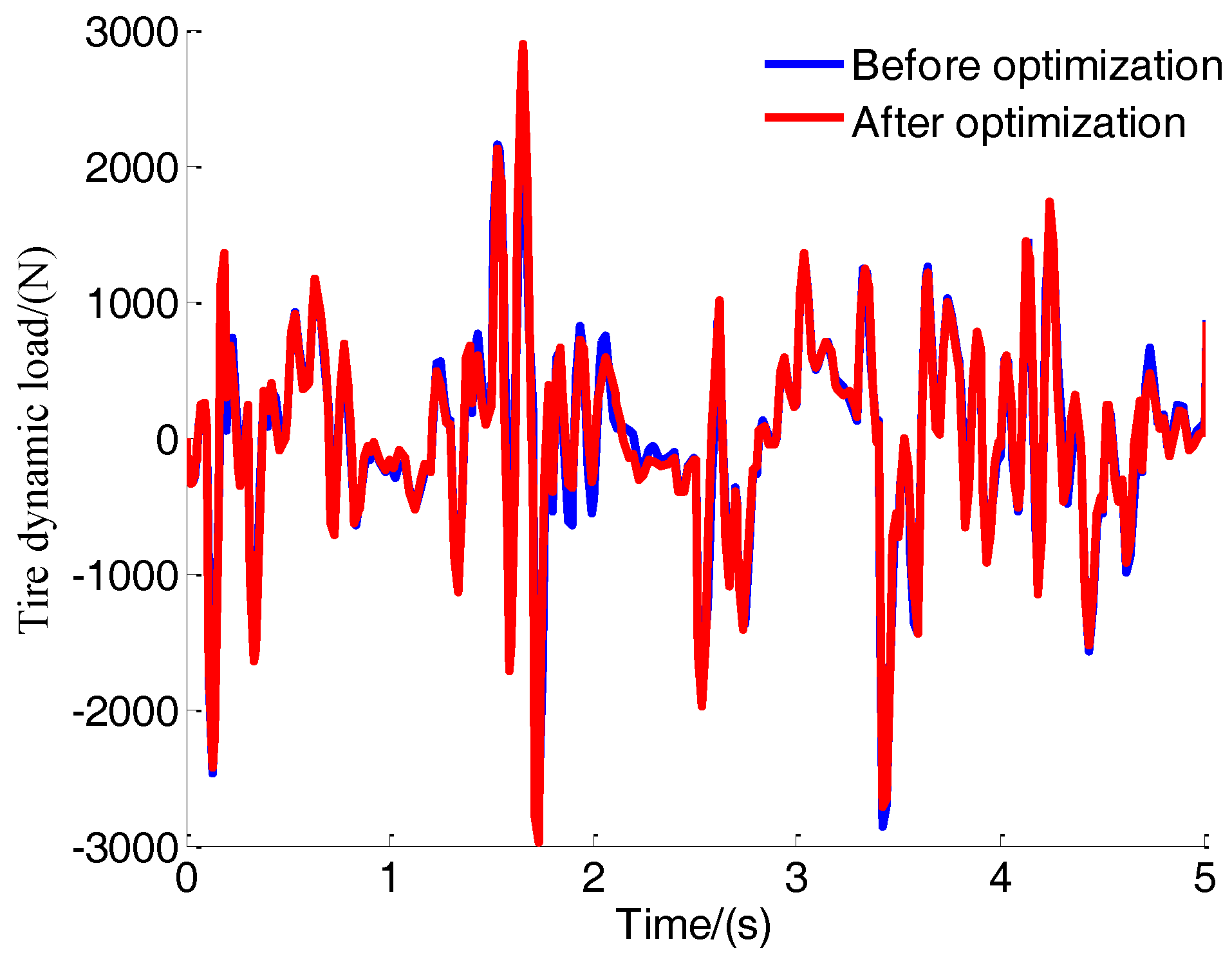
| Tire dynamic load | 802.7 | 701.5 | −12.61 | |
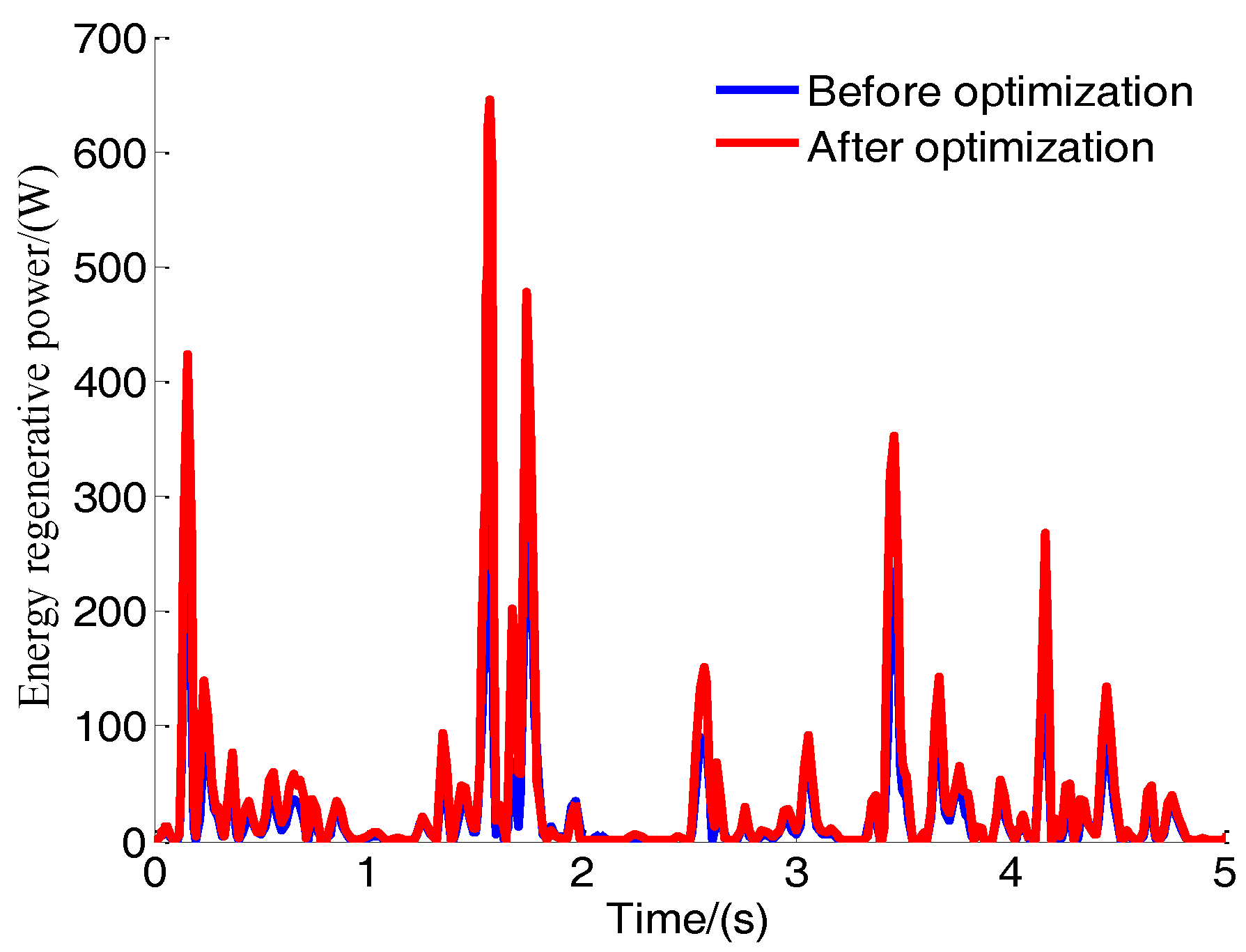
| Energy regenerative power | 59.82 | 89.53 | 49.67 | |
| Energy regenerative efficiency | 18.68 | 27.26 | 45.93 | |
© 2018 by the authors. Licensee MDPI, Basel, Switzerland. This article is an open access article distributed under the terms and conditions of the Creative Commons Attribution (CC BY) license (http://creativecommons.org/licenses/by/4.0/).
Share and Cite
Kou, F.; Du, J.; Wang, Z.; Li, D.; Xu, J. Nonlinear Modeling and Coordinate Optimization of a Semi-Active Energy Regenerative Suspension with an Electro-Hydraulic Actuator. Algorithms 2018, 11, 12. https://doi.org/10.3390/a11020012
Kou F, Du J, Wang Z, Li D, Xu J. Nonlinear Modeling and Coordinate Optimization of a Semi-Active Energy Regenerative Suspension with an Electro-Hydraulic Actuator. Algorithms. 2018; 11(2):12. https://doi.org/10.3390/a11020012
Chicago/Turabian StyleKou, Farong, Jiafeng Du, Zhe Wang, Dong Li, and Jianan Xu. 2018. "Nonlinear Modeling and Coordinate Optimization of a Semi-Active Energy Regenerative Suspension with an Electro-Hydraulic Actuator" Algorithms 11, no. 2: 12. https://doi.org/10.3390/a11020012
APA StyleKou, F., Du, J., Wang, Z., Li, D., & Xu, J. (2018). Nonlinear Modeling and Coordinate Optimization of a Semi-Active Energy Regenerative Suspension with an Electro-Hydraulic Actuator. Algorithms, 11(2), 12. https://doi.org/10.3390/a11020012