1. Introduction
Typical colloidal particles with appropriate wettability can be irreversibly adsorbed at fluid–fluid interfaces (e.g., oil–water and air–water interfaces) [
1,
2]. Strong particle adsorptions can decrease interfacial tension and stabilize the interface, thereby preventing phase separation and coalescence in emulsion systems. In particular, chemically homogeneous colloidal particles likely impart kinetic stability in Pickering emulsions stabilized by solid particles [
3,
4]. The efficacy of interfacial stability is highly dependent on the relative amount of each fluid phase and particle wettability (polarity or apolarity) with regard to the fluid–fluid interface that can be characterized via three-phase contact angles.
Janus particles that possess chemical and/or geometric anisotropy can improve the stabilization efficiency of Pickering emulsion systems when used as stabilizers [
5,
6,
7,
8,
9,
10,
11,
12,
13,
14,
15]. This is because Janus particles tend to be aligned toward increasing the surface area of preferred wetting (e.g., apolar surfaces exposed to oil and polar surfaces exposed to water), resulting in effectively reduced surface free energy. Additional degrees of freedom gained from anisotropic properties can lead to diversity in configurational behaviors (upright or tilted) when attached to a fluid–fluid interface [
16,
17,
18,
19,
20]. It is important to note that configurations on the single-particle level can significantly affect interactions between particles at the interface, their assembly structures, and consequently the rheological properties of the interface [
21,
22,
23,
24,
25,
26,
27,
28,
29,
30,
31]. For instance, Janus spheres with two chemically different sides (apolar and polar surfaces) generally adopt an upright orientation corresponding to the geometry in which the Janus boundary or wettability separating line (WSL) is pinned to the fluid–fluid interface [
32]. With regard to non-spherical Janus particles (e.g., Janus ellipsoids, Janus dumbbells, and Janus cylinders), particle configurations can be either upright or tilted, depending on the relative influence of chemical and geometric factors. Particularly, particles adopted tilted configurations when the geometric effect (e.g., aspect ratio,
AR) is stronger than the chemical effect (e.g., wettability), whereas particles under the opposite conditions adopted upright configurations. Janus particles with tilted configurations likely deformed their surrounding fluid interface due to unpreferred wetting (e.g., apolar surfaces exposed to water, and vice versa), and the resulting interface deformation led to lateral capillary interactions between particles to minimize the surface areas of the deformed interfaces [
33,
34,
35,
36,
37,
38,
39]. Capillary interactions between particles at the interface directly affected their microstructure, and therefore the rheological properties of the particle-laden interface. Effects of configuration at the single-particle level on interparticle interactions were experimentally demonstrated using Janus cylinders with apolar and polar surfaces prepared via PDMS (Polydimethylsiloxane) molding techniques [
33,
34,
40]. Apolar and polar precursor solutions were added to a PDMS mold with cylindrical wells one after another, and subsequent UV exposure led to photopolymerization of the precursor solution, resulting in Janus cylinders. The aspect ratio and relative lengths of the two sides could be readily controlled depending on the well depth in the mold and the amount of each precursor solution. Janus cylinders with high
AR values adopted tilted configurations and exhibited strong capillary attractions. In contrast, low
AR particles adopted upright configurations and attractive interactions occurred negligibly.
The configurational behaviors of two types of non-spherical Janus particles (i.e., Janus ellipsoids and Janus dumbbells) have been theoretically investigated by numerically calculating the attachment energy at the fluid–fluid interface as a function of orientation angle [
16,
17]. With regard to Janus dumbbells, a single energy minimum occurred in the attachment energy profile, indicating that the Janus dumbbells exclusively adopted either an upright or a tilted configuration. Interestingly, for Janus ellipsoids with particular
AR and wettability values, two energy minima appeared in the attachment energy profile; one corresponding to an upright configuration, and the other to a tilted configuration—one of the two configurations should be kinetically stable. With regard to Janus ellipsoids, it is unknown whether the Janus boundary of the particles can be detached or unpinned from the fluid–fluid interface, regardless of configuration. These pinning and unpinning behaviors might depend on the relative effect of chemical and geometric anisotropy. Indeed, it was previously reported that the Janus boundary of Janus spheres could be unpinned from the interface when the boundary significantly deviated from the central region of the particles [
2,
32]. In this study, we quantitatively investigate the effects of geometric and chemical factors of Janus ellipsoids on the pinning and unpinning behaviors of the Janus boundary at the fluid interface. We also relate the unpinned configuration to the tilted configuration when the
AR value is larger than 1.
2. Theoretical Basis
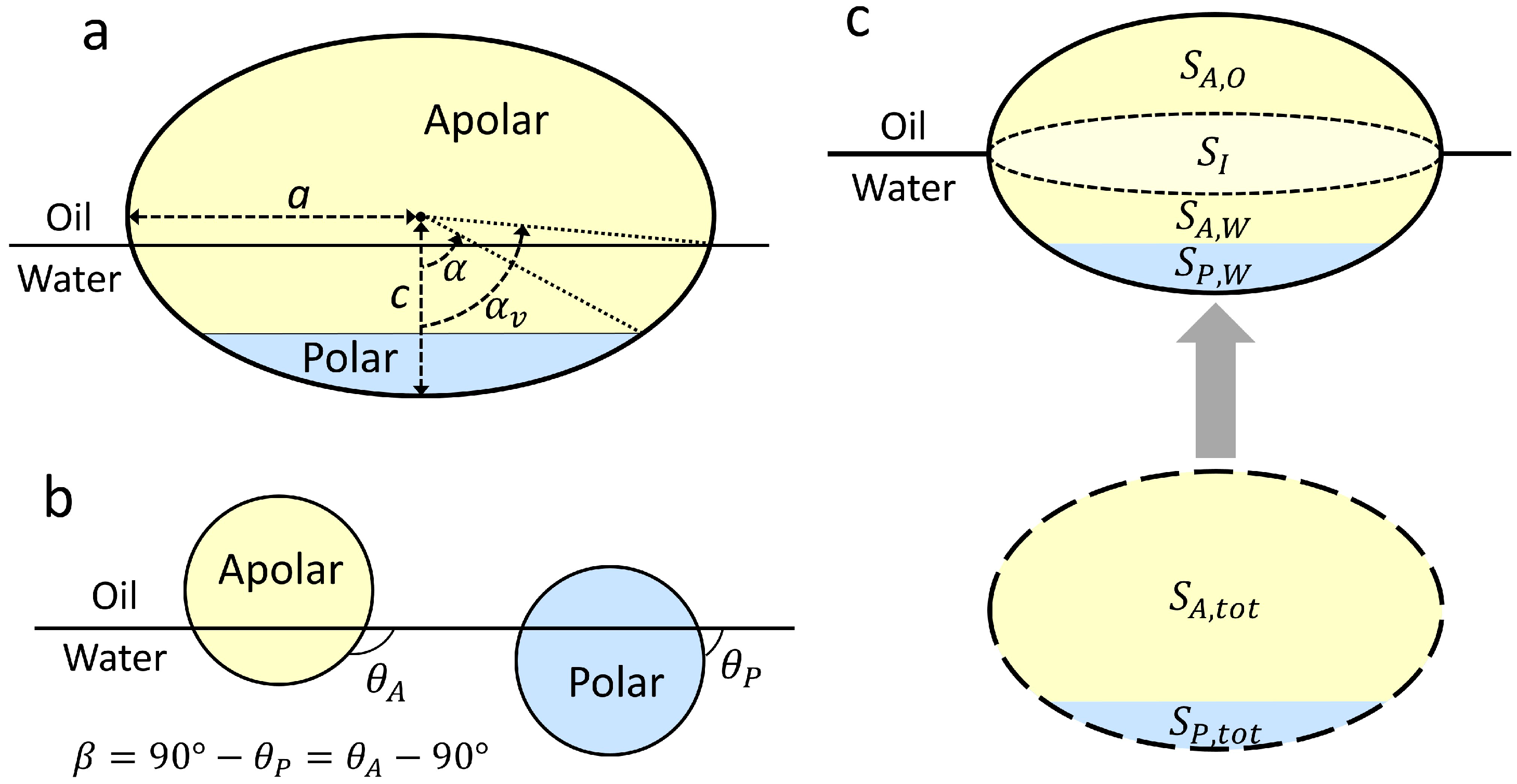
To characterize the geometric and chemical anisotropy of Janus ellipsoids, we define the aspect ratio (
AR), the location of the Janus boundary (
α), and the supplementary wettability (
β) as shown in
Figure 1a,b. The aspect ratio is the ratio of the major axis to the minor axis, calculated by
AR =
c/
a. Depending on the value of
AR, the ellipsoids are prolate or oblate at
AR > 1 and
AR < 1, respectively, with a sphere formed at
AR = 1. We designate all studied particles as Janus ellipsoids. The Janus boundary that indicates the wettability separation line (WSL) dividing polar and apolar regions is characterized by an elevation angle,
α. The supplementary wettability is defined as
, in which
and
indicate the three-phase contact angles of homogeneous polar (
α = 180°) and apolar (
α = 0°) spheres when trapped at an oil–water interface, respectively (
Figure 1b).
Based on these geometric relationships, the attachment energy of a particle that is attached to a planar oil–water interface from the water phase (
Figure 1c) is given by [
1,
2,
16,
17]
The respective energies of a particle at the oil–water interface (
EI) and a particle immersed in the aqueous phase (
Ew) are
where
Sij is the surface area (
i =
P (polar) or
A (apolar)) exposed to a fluid phase (
j =
w (water) or
o (oil)),
γij is the corresponding surface energy of surface
i and fluid
j,
and
are the surface area values of the oil–water interface when particles are present and absent, respectively, and
indicates the displaced area of the interface due to presence of the particle. The displaced area (
SI) corresponds to the cross-sectional area of the particle at
αv, which is the elevation angle measured from the major axis to the fluid interface (i.e., the three phase contact line), as shown in
Figure 1a.
and
are the total surface area values of the apolar and polar regions of the particle, respectively. Substitution of the following Young’s Equations:
into Equations (1)–(3) yields the following:
Similarly, the attachment energy of a Janus particle from the oil phase to the oil–water interface can be expressed as:
The difference between Equations (6) and (7) is the reference energy state (i.e.,
Ew and
Eo); therefore, the shapes of the attachment energy profiles obtained from the equations should be identical. Since the use of either Equation (6) or (7) predicts the same configurational behavior, Equation (6) is used in this work. To calculate the surface area
Sij, a numerical method using the hit-and-miss Monte Carlo method is employed [
16]. The oil–water interfacial tension value is arbitrarily designated as
γow = 50 mN/m, corresponding to the interfacial tension of a decane–water interface.
In the numerical calculations, it is assumed that the meniscus at the particle interface is smooth. The effect of line tension at the three-phase contact line can be neglected when the particle dimensions are sufficiently large (e.g., >10 nm) [
15,
41]. In this case, the effect of the Brownian motion of particles on the configuration behaviors is also negligible [
16]. The oil–water interface around the particle is assumed to be flat when the particle size is less than a few hundred microns, in which the corresponding Bond number (ratio of gravitational force to surface tension force) is sufficiently small. Although interfacial deformation around the particles is possible for non-spherical Janus particles, it was previously demonstrated that the flat interface assumption (FIA) with regard to the attachment energy calculations was appropriate to determine the equilibrium configurations of the particles at the fluid–fluid interface [
16]. Moreover, it was reported that the configuration behaviors of Janus cylinders predicted from the numerical calculations based on the FIA showed a good agreement with the experimental observations [
33,
34]. Note that in spite of the consistency between the experimental and theoretical results for the configuration behaviors when the FIA is used, interfacial deformation around Janus particles with a tilted configuration can occur, leading to capillary-induced interactions between the tilted Janus particles [
33,
34,
35]. Based on these conditions and methods, the attachment energy is calculated as a function of vertical position,
αv. To evaluate whether the Janus boundary of the particles is pinned or unpinned at the oil–water interface, the attachment energy is minimized to obtain the lowest energy minimum,
, and the corresponding vertical position ,
αv,min.
Notably, for Janus prolates with
AR > 1, there are four possible cases in their configuration behaviors, depending on
AR and wettability values, such as the upright only, the upright equilibrium/tilted metastable, the tilted equilibrium/upright metastable, and the tilted only regions [
16,
17]. For the co-existing regions, for instance, two energy minima appear in the attachment energy profiles, indicating that particles can adopt either upright or tilted configurations, whereas particles in the titled only region possess only the tilted configuration. Therefore, to further determine the configuration behaviors (upright or/and tilted) of the Janus prolates, the attachment energy is calculated as functions of the vertical position (
αv) as well as the orientation angle (0° <
θr < 90°), in which
θr = 0° and 90° indicate the geometries of the Janus boundary parallel and perpendicular to the interface, respectively. In this case, the attachment energy is scanned by varying the
αv values at a constant
θr. The minimum attachment energy is then calculated at the given
θr value, and the same procedure is repeated for different values of
θr to find a global energy minimum,
.
For spherical Janus particles with supplementary wettability (i.e.,
and
), the attachment energy from the water phase (Equation (6)) can be further simplified using geometric relationships. In particular, when the Janus boundary of a Janus sphere is pinned at the oil–water interface, the surface areas of the apolar and polar regions exposed to the oil phase are
and
, respectively. The displaced area in this geometry is
. Therefore, Equation (6) becomes,
Equation (8) should satisfy the condition of at for the Janus sphere with the pinned Janus boundary, yielding , and thus .
3. Results and Discussion
Pinning (
α =
αv,min) and unpinning (
α ≠
αv,min) behaviors of the Janus particles with respect to the interfaces can be determined through two competing factors: geometric and chemical anisotropy. To minimize the attachment energy in Equation (6), a Janus particle tends to be aligned toward increasing the displaced area (
SI) at the oil–water interface, simultaneously increasing the surface area of the preferred wetting state (
SAo; note that
). The state of preferred wetting indicates the configuration of the apolar and polar regions exposed to their favorable fluid phases, oil and water, respectively. Depending on the relative influence of these two factors, the particle is likely to preferentially adopt the pinned configuration when wettability effects are greater than geometric effects, whereas particles are unpinned from the interface when geometric effects are dominant. Notably, Janus prolates can adopt the two configurations, the upright and tilted one (e.g., when the
AR value is high and wettability is moderate) [
16]. In this particular case, the attachment energy may be further decreased by rotating the particle at the interface. We also examine the relationship between the pinning/unpinning and the upright/tilted configuration behaviors.
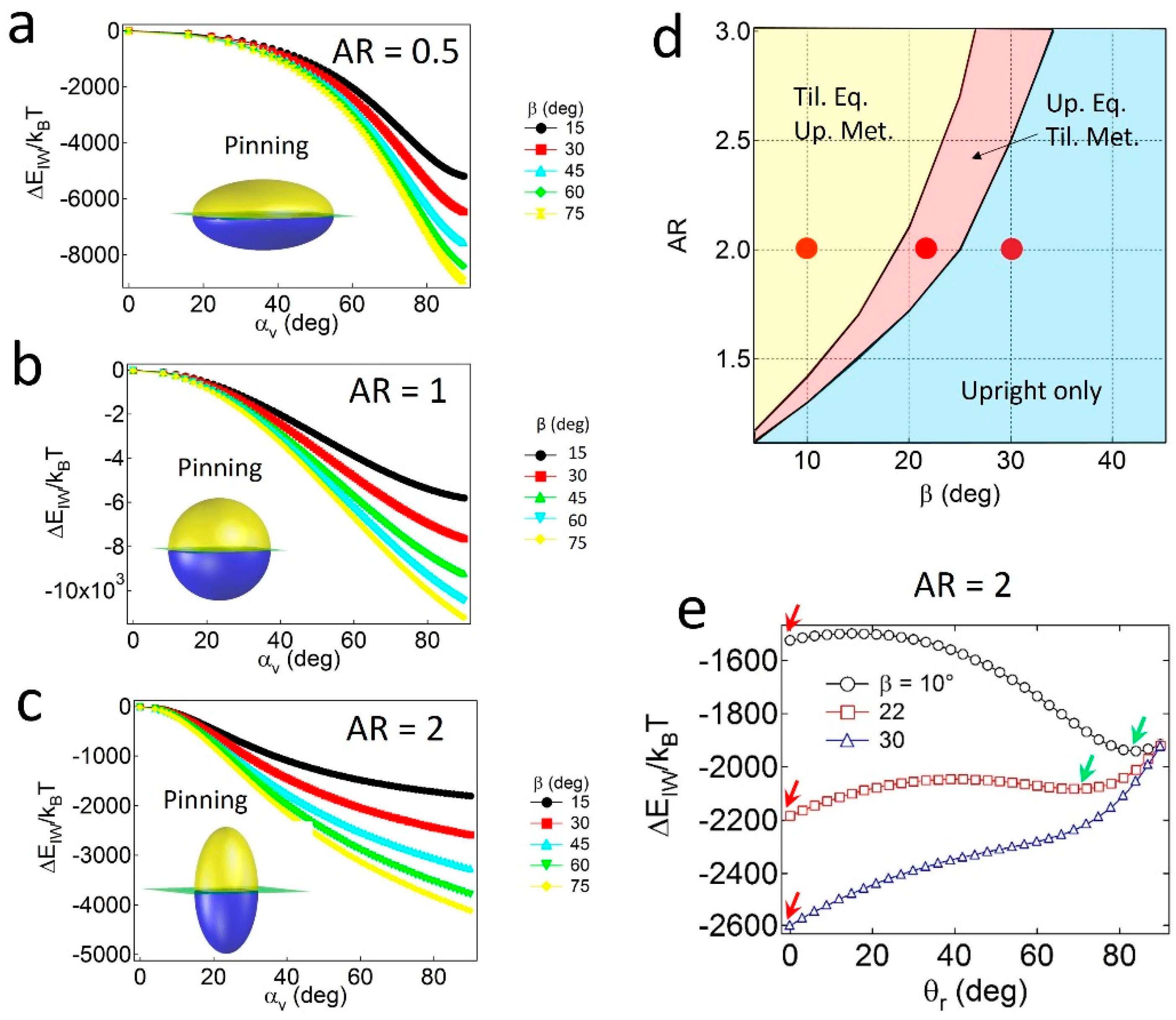
To investigate the effects of geometry (AR and α) and wettability (β) on the pinning and unpinning behaviors of Janus ellipsoids, the attachment energy () is calculated as a function of αv at constant values of β and AR = 0.5 (oblate), 1 (sphere), or 2 (prolate). Since the supplementary wettability (β) is used and Janus particles with α ≤ 90° are considered, is calculated in the range of . Note that similar results can be obtained in the case of Janus ellipsoids with α > 90°.
For the Janus ellipsoids with
α = 90°—in which the polar and apolar surface area values are identical—the lowest energy minimum (
) for all cases is found at
αv,min = 90°, as shown in
Figure 2a–c. The result of
α =
αv,min indicates that the Janus boundary of the geometrically symmetric Janus ellipsoids is always pinned at the oil–water interface, regardless of the values of
AR and
β. The pinned configuration of the particles simultaneously satisfies both conditions; that is, the particles tend to possess maximum values of the displaced area (
SI) and preferred wetting (
SAo) in Equation (6) when
α =
αv,min.
Janus prolates with particular
AR and
β values can also adopt the tilted configuration. As shown in the configuration phase diagram in
Figure 2d, particles with relatively high
β and low
AR values only possess the upright or the pinned configuration (light blue region), whereas two coexisting regions (pink and yellow regions) appear when particles carry the opposite properties (i.e., relatively low
β and high
AR values). For instance, for particles with
AR = 2 and
β = 10° or 22° (denoted as red dots in
Figure 2d), two energy minima exist in the attachment energy profiles in
Figure 2e; that is, one corresponds to the upright (red arrow) and the other to the tilted one (green arrow). In contrast, a single energy minimum for the particle with
AR = 2 and
β = 30° (
Figure 2e) indicates that the particle solely adopts the upright configuration. Notably, the absence of a tilted only region in
Figure 2d might be related to the absence of the unpinned configuration. In other words, since the Janus boundary of the particles with
α = 90° can always be pinned to the interface, regardless of the values of
AR and
β, at least one of the energy minima in the attachment energy profiles should exist at
θr = 0.
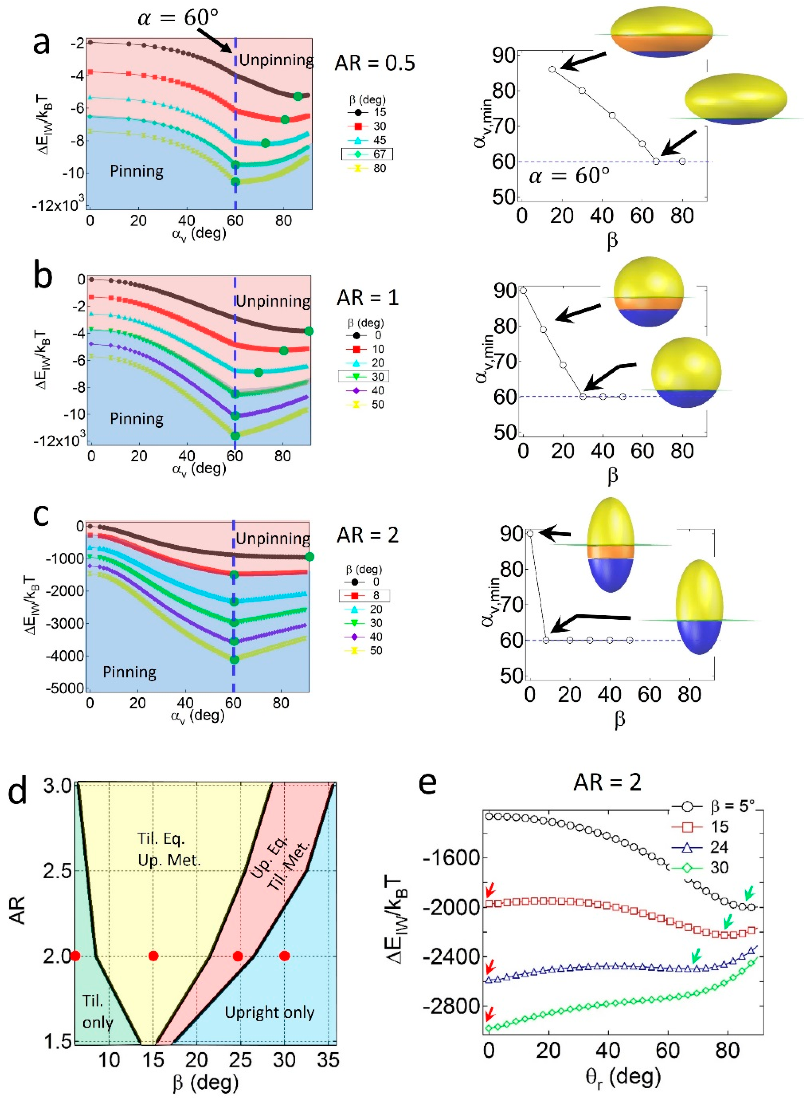
When the particles are geometrically asymmetric (
α = 60°), configuration behavior depends on the relative geometry and wettability effects. As shown in
Figure 3a, for oblates with
AR = 0.5, the value of
αv,min at
gradually decreases with
β, and is not consistent with
α if the value of
β is not sufficiently high. The condition of
αv,min =
α indicates that a pinned geometry is found at a critical value of
β, in which
βc = 67°. Similar results are found for spheres with
AR = 1 (
Figure 3b) and prolates with
AR = 2 (
Figure 3c) when
α = 60°, in which the critical wettability values are
βc = 30° and 8°, respectively. The increase in
βc for lower
AR particles is due to the relatively large displaced area (
SI) around the central regions of the particles; thus, the geometric effects become stronger than the wettability effects. Note that the value of
βc = 30° for the Janus sphere obtained from the numerical calculation is consistent with the theoretical prediction of
, validating the numerical method.
The configuration behaviors of geometrically asymmetric Janus prolates are also affected by the presence of the secondary energy minimum in the attachment energy profile. As shown in the configuration phase diagram of Janus prolates with
α = 60° in
Figure 3d, four distinct regions are observed; the tilted only (light green), the tilted equilibrium/upright metastable (yellow), the upright equilibrium/tilted metastable (pink), and the upright only (light blue) regions. The example attachment energy profiles as a function of
θr are shown in
Figure 3e, and the corresponding energy minima are indicated by red and green arrows. Unlike the Janus prolates with
α = 90°, it is interesting to note that the tilted only region is found at the conditions of relatively high
AR and low
β values. The presence of the tilted only region is likely due to the presence of the unpinning configuration of the particles; that is, when the prolate particles are unpinned, no energy minimum exists at
θr = 0, and consequently, the particles only adopt the tilted configuration. In contrast, when the Janus boundary of prolate particles are pinned to the interface in
Figure 3c, they essentially possess an energy minimum at
θr = 0, leading to the upright/tilted coexisting regions (yellow and pink areas in
Figure 3d) or the upright only region (light blue in
Figure 3d). Note that the
βc = 8° value for the Janus prolate with
AR = 2 in
Figure 3c shows a good agreement with the boundary between the light green and yellow regions in the
Figure 3d.
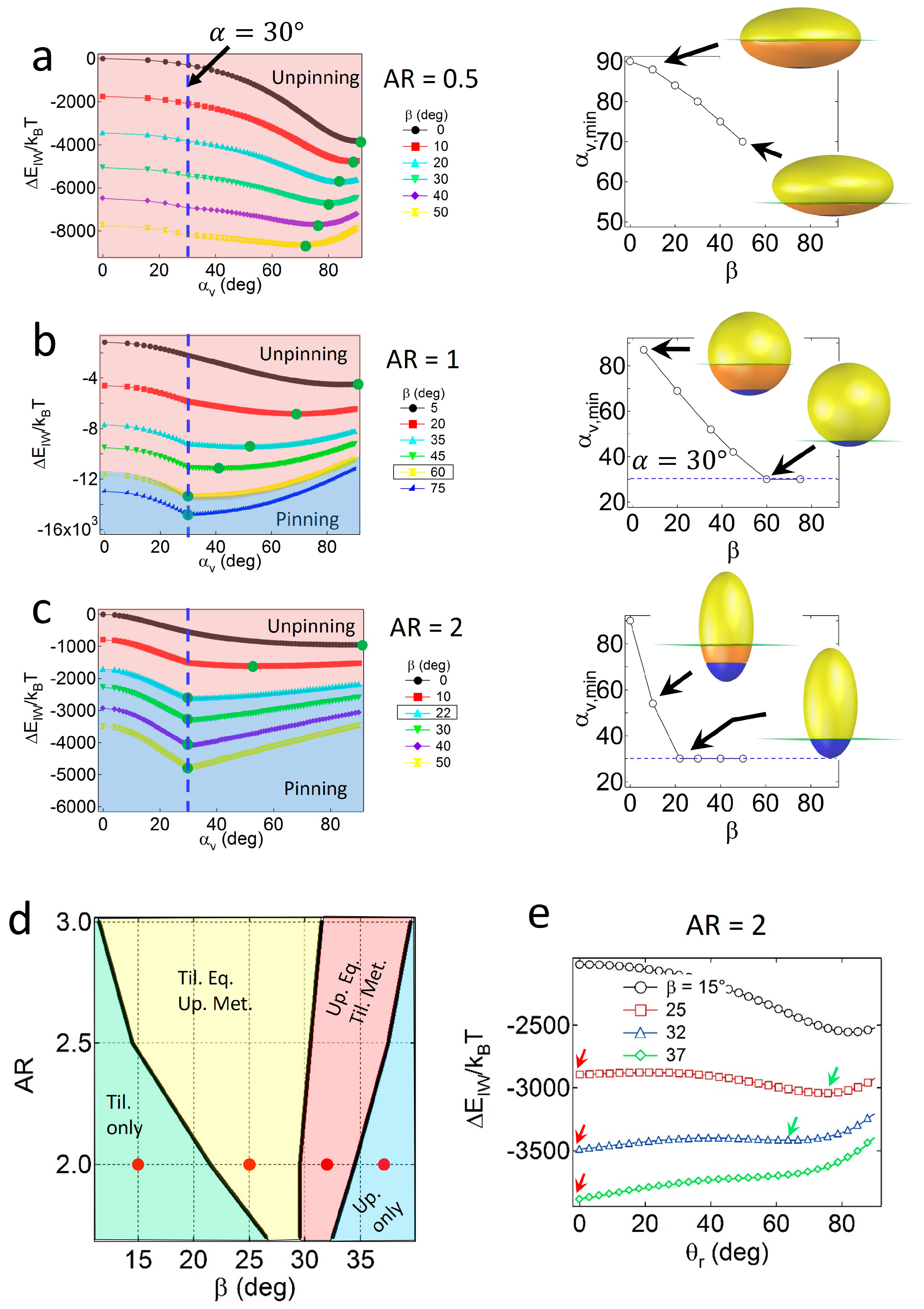
For Janus ellipsoids with a high degree of geometric asymmetry (
α = 30°), strong wettability effects are required to preserve the pinned configuration. As shown in
Figure 4a, for oblates with
AR = 0.5, the value of
αv,min consistently decreases as
β increases, and does not match the value of
α = 30° up to
β = 50°. Due to large values of
SI around the central regions of the oblate, geometric effects are likely to be dominant to wettability effects, resulting in particles with central regions located at the interface, adopting an unpinned configuration. For Janus ellipsoids with lower
AR values, wettability effects gradually become significant. As shown in
Figure 4b,c, the Janus boundaries of Janus ellipsoids with
AR = 1 and 2 are pinned to the interface when the critical wettability value is
βc = 60° or 22°. Note that the value of
βc increases as the particles become more geometrically asymmetric (
βc = 30° and 8° for particles (
α = 60°) with
AR = 1 and 2, respectively).
Similar to the case of the Janus prolates with
α = 60°, the four distinct regions in the configuration phase diagram for the prolate particles with
α = 30° are found, as shown in
Figure 4d. Example attachment energy profiles as a function of
θr, representing each configuration region and the location of energy minima, are shown in
Figure 4e. The tilted only region (light green area) in relatively high
AR and low
β values corresponds to the condition where the Janus boundary of particles is unpinned. For particles with
AR = 2, for instance, the boundary between the light green and the yellow regions in
Figure 4e is consistent with the critical wettability value,
βc = 22° in
Figure 4c. Except for the tilted only region, a portion of the particles always adopts the upright configuration due to the presence of an energy minimum at the pinned geometry in
Figure 4c.
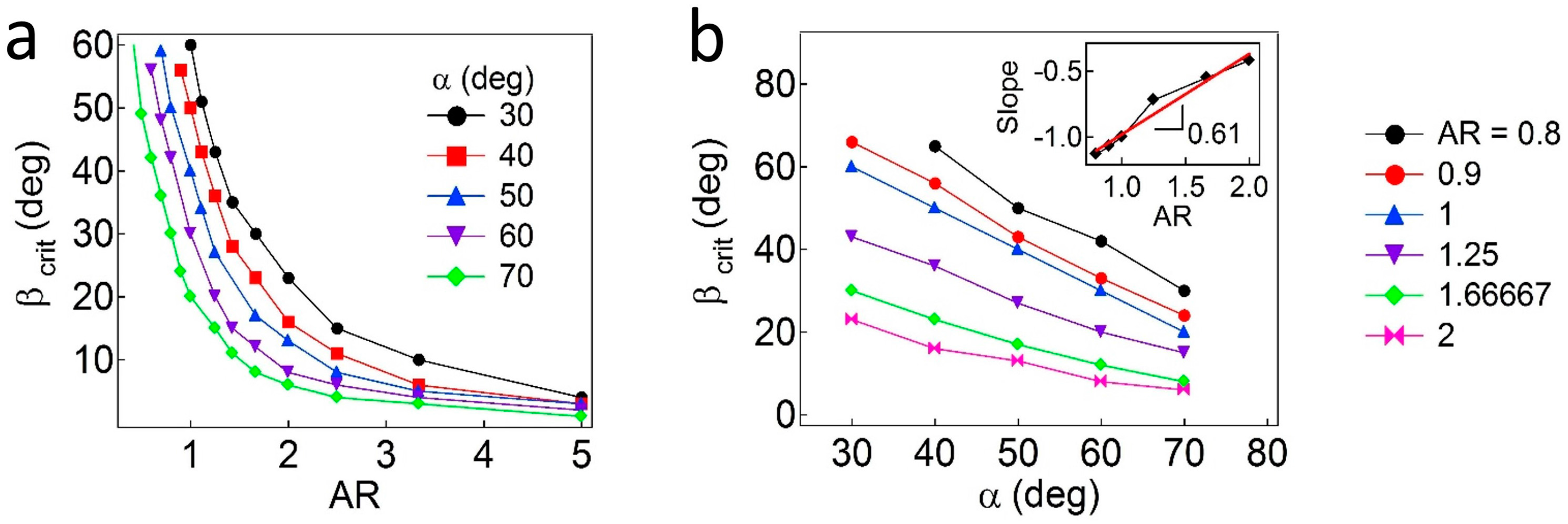
Additionally, the critical values of
β are further calculated as functions of
AR and
α. As shown in
Figure 5a, the regions above each curve correspond to the pinned Janus boundary at the interface, whereas the regions below the curve indicate that the Janus boundary is unpinned from the interface. In general, the value of
βc (due to wettability effects) is inversely proportional to the values of
α and
AR, which are due to geometric effects. As the values of
AR decrease, the particles demonstrate reduced attachment energy when the interface is located at the central regions of the particles. When the value of
α decreases (the particles become more geometrically asymmetric), a higher value of
β is required to adopt a pinned configuration. More quantitatively, to find a relationship of
βc,
α, and
AR, the
βc values are plotted as a function of
α, as shown in
Figure 5b. Then, slopes (
) obtained from linear regression of each line representing different
AR values are shown in the inset plot in
Figure 5b, in which the slope (
) is found to be ~0.61 ± 0.06. Based on the values of
when
AR = 1, an empirical relationship for Janus ellipsoids is obtained,
.
Finally, it is notable that when the Janus boundary of Janus prolates (
AR > 1) with
β <
βc is unpinned, they rotate and adopt the tilted configuration to further decrease their attachment energy by increasing the displaced area (
SI) [
16,
17] and, consequently, all portions of the particles would adopt the tilted configuration. In this case, the
βc value corresponds to the boundary between two configuration regions—the tilted only and the tilted equilibrium/upright metastable regions.

