
Corrosion Inhibition of High Speed Steel by Biopolymer HPMC Derivatives


Abstract
:1. Introduction
2. Results and Discussion
2.1. Film preparation and Characteristics Measurement
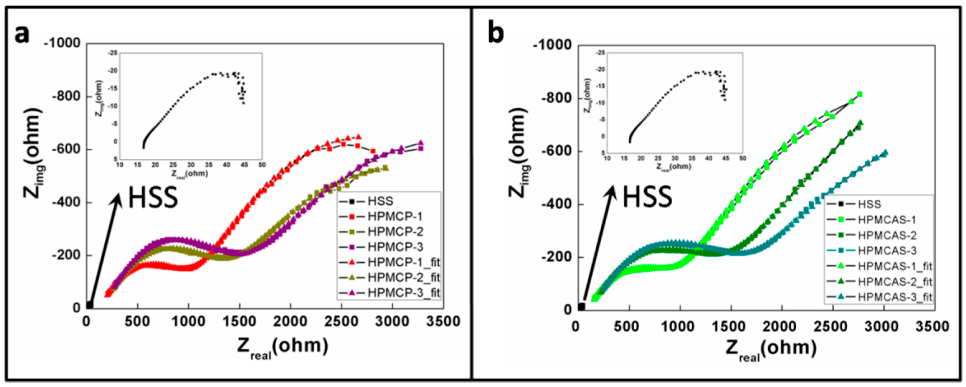
2.2. Anti-Corrosion Behavior
3. Materials and Methods
3.1. Film Preparation and Characteristics Measurement
3.2. Anti-Corrosion Behavior
4. Conclusions
- (1)
- The corrosion resistance performance of green polymer material HPMC derivatives was demonstrated.
- (2)
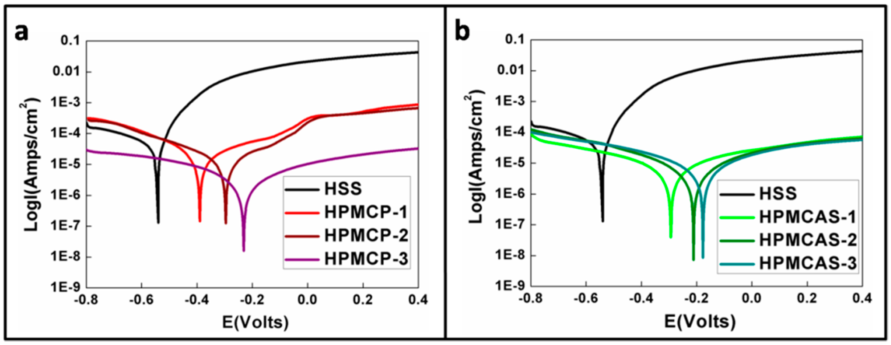
- Both EIS and PP suggested promising corrosion resistance performance of HPMCP and HPMCAS.
- (3)
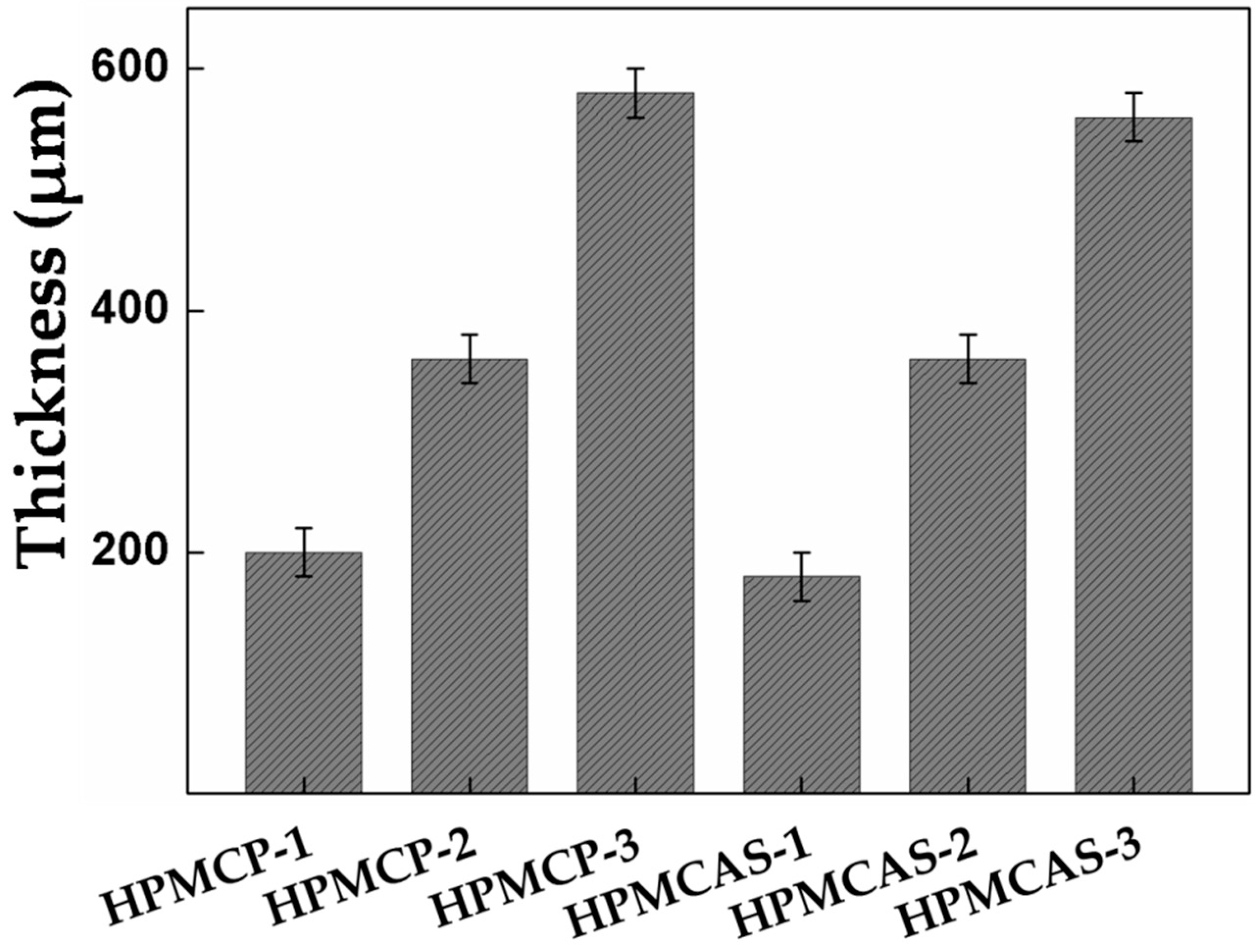
- The film thickness of HPMC derivatives was positively correlated the corrosion resistance ability.
- (4)
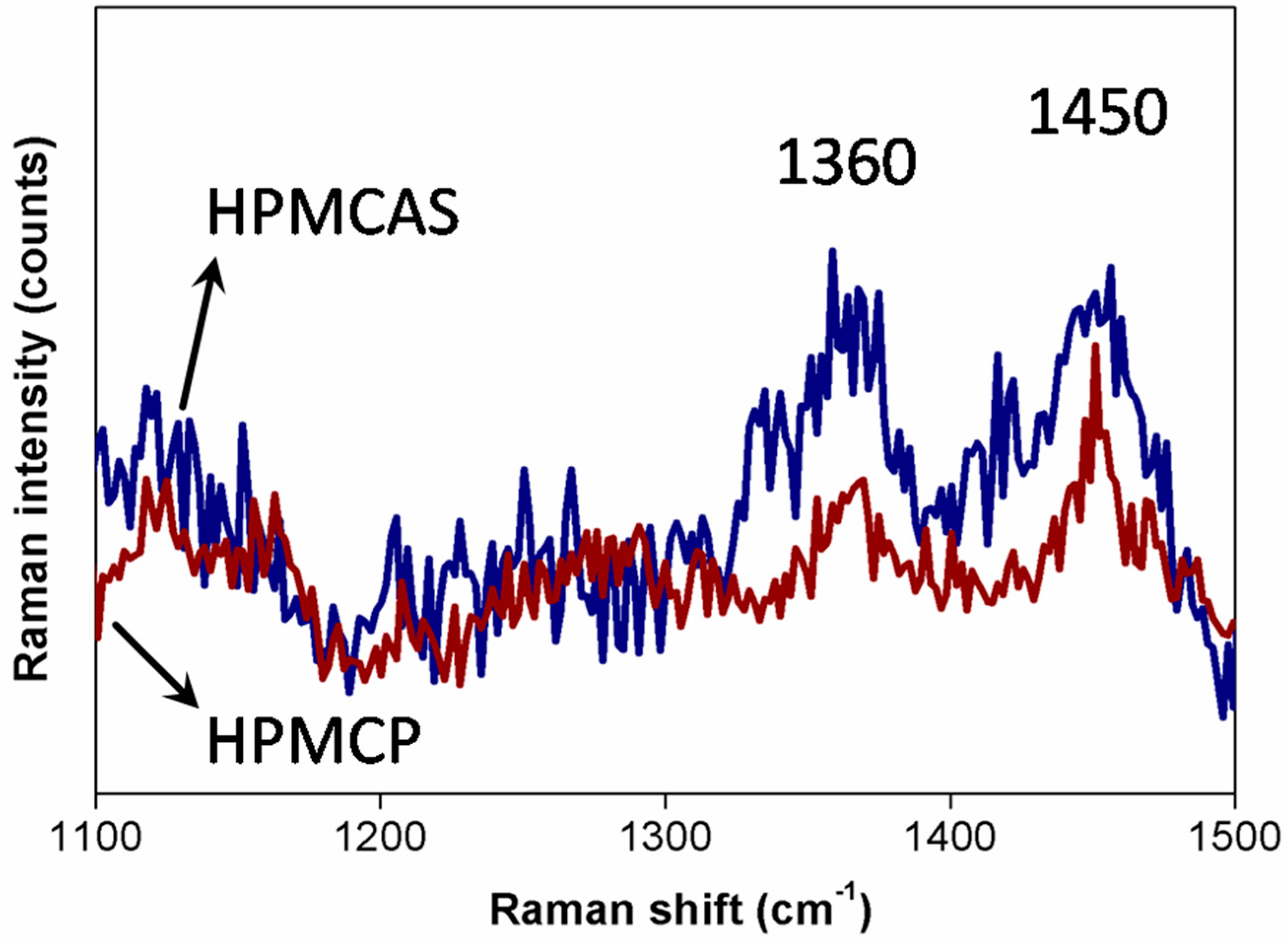
- HPMCP has hydrophobic surface and low moisture content; thus, it provided better anti-corrosion protection than HPMCAS.
Acknowledgments
Author Contributions
Conflicts of Interest
Abbreviations
| NCKU | National Cheng Kung University |
| HPMC | hydroxypropyl methylcellulose |
| HPMCP | hydroxypropyl methylcellulose phthalate |
| HPMCAS | hydroxypropyl methylcellulose acetate succinate |
| HSS | high speed steel |
| PP | potentiodynamic polarization |
References
- Kawahara, Y. High temperature corrosion mechanisms and effect of alloying elements for materials used in waste incineration environment. Corros. Sci. 2002, 44, 223–245. [Google Scholar] [CrossRef]
- Bentiss, F.; Jama, C.; Mernari, B.; El Attari, H.; El Kadi, L.; Lebrini, M.; Traisnel, M.; Lagrenée, M. Corrosion control of mild steel using 3,5-bis(4-methoxyphenyl)-4-amino-1,2,4-triazole in normal hydrochloric acid medium. Corros. Sci. 2009, 51, 1628–1635. [Google Scholar] [CrossRef]
- Hare, C. Corrosion control of steel by organic coatings. In Uhlig’s Corrosion Handbook, 3rd ed.; John Wiley & Sons: Hoboken, NJ, USA, 2000; pp. 971–983. [Google Scholar]
- Kilmartin, P.A.; Trier, L.; Wright, G.A. Corrosion inhibition of polyaniline and poly (O-methoxyaniline) on stainless steels. Synth. Met. 2002, 131, 99–109. [Google Scholar] [CrossRef]
- Chang, K.-C.; Hsu, M.-H.; Lu, H.-I.; Lai, M.-C.; Liu, P.-J.; Hsu, C.-H.; Ji, W.-F.; Chuang, T.-L.; Wei, Y.; Yeh, J.-M. Room-temperature cured hydrophobic epoxy/graphene composites as corrosion inhibitor for cold-rolled steel. Carbon 2014, 66, 144–153. [Google Scholar] [CrossRef]
- Nordsveen, M.; Nešic, S.; Nyborg, R.; Stangeland, A. A mechanistic model for carbon dioxide corrosion of mild steel in the presence of protective iron carbonate films–part 1: Theory and verification. Corrosion 2003, 59, 443–456. [Google Scholar] [CrossRef]
- Okafor, P.; Liu, X.; Zheng, Y. Corrosion inhibition of mild steel by ethylaminoimidazoline derivative in CO2-saturated solution. Corros. Sci. 2009, 51, 761–768. [Google Scholar] [CrossRef]
- Liu, H.; Gu, T.; Zhang, G.; Wang, W.; Shuang, D.; Cheng, Y.; Liu, H. Corrosion inhibition of carbon steel in CO2-containing oilfield produced water in the presence of iron-oxidizing bacteria and inhibitors. Corros. Sci. 2016, 105, 149–160. [Google Scholar] [CrossRef]
- Badr, S.; Abdallah, M. Preparation of new saturated polyamide compounds and its application as corrosion inhibitors for corrosion of carbon steel in hydrochloric acid solution. Zaštitamaterijala 2009, 50, 213–221. [Google Scholar]
- Umoren, S.A.; Li, Y.; Wang, F.H. Effect of polyacrylic acid on the corrosion behaviour of aluminium in sulphuric acid solution. J. Solid State Electrochem. 2010, 14, 2293–2305. [Google Scholar] [CrossRef]
- Arthur, D.E.; Jonathan, A.; Ameh, P.O.; Anya, C. A review on the assessment of polymeric materials used as corrosion inhibitor of metals and alloys. Int. J. Ind. Chem. 2013, 4, 1–9. [Google Scholar] [CrossRef]
- Arukalam, I.; Madufor, I.; Ogbobe, O.; Oguzie, E. Cellulosic polymers for corrosion protection of aluminium. Int. J. Eng. Tech. Res. 2015, 3, 2321–0869. [Google Scholar]
- Abiola, O.K.; James, A. The effects of aloe vera extract on corrosion and kinetics of corrosion process of zinc in hcl solution. Corros. Sci. 2010, 52, 661–664. [Google Scholar] [CrossRef]
- Eddy, N.O. Inhibitive and adsorption properties of ethanol extract of colocasiaesculenta leaves for the corrosion of mild steel in H2SO4. Int. J. Phys. Sci. 2009, 4, 165–171. [Google Scholar]
- Kumpawat, V.; Garg, U.; Tak, R. Corrosion inhibition of aluminium in acid media by naturally occurring plant Artocarpus heterophyllus and Acacia senegal. J. Indian Counc. Chem. 2009, 26, 82–84. [Google Scholar]
- Lebrini, M.; Robert, F.; Lecante, A.; Roos, C. Corrosion inhibition of C38 steel in 1Mhydrochloric acid medium by alkaloids extract from Oxandra asbeckii plant. Corros. Sci. 2011, 53, 687–695. [Google Scholar] [CrossRef]
- Byun, Y.; Ward, A.; Whiteside, S. Formation and characterization of shellac-hydroxypropyl methylcellulose composite films. Food Hydrocoll. 2012, 27, 364–370. [Google Scholar] [CrossRef]
- Al-Tabakha, M.M. HPMC capsules: Current status and future prospects. J. Pharm. Pharm. Sci. 2010, 13, 428–442. [Google Scholar] [CrossRef] [PubMed]
- Brogly, M.; Fahs, A.; Bistac, S. Surface properties of new-cellulose based polymer coatings for oral drug delivery systems. Polym. Prepr. 2011, 52, 1054–1055. [Google Scholar]
- Joshi, S.C. Sol-gel behavior of hydroxypropylmethylcellulose (HPMC) in ionic media including drug release. Materials 2011, 4, 1861–1905. [Google Scholar] [CrossRef]
- Zhou, D.; Law, D.; Reynolds, J.; Davis, L.; Smith, C.; Torres, J.L.; Dave, V.; Gopinathan, N.; Hernandez, D.T.; Springman, M.K. Understanding and managing the impact of HPMC variability on drug release from controlled release formulations. J. Pharm. Sci. 2014, 103, 1664–1672. [Google Scholar] [CrossRef] [PubMed]
- Bárcenas, M.E.; Rosell, C.M. Effect of HPMC addition on the microstructure, quality and aging of wheat bread. Food Hydrocoll. 2005, 19, 1037–1043. [Google Scholar] [CrossRef]
- Villalobos, R.; Hernández-Muñoz, P.; Chiralt, A. Effect of surfactants on water sorption and barrier properties of hydroxypropyl methylcellulose films. Food Hydrocoll. 2006, 20, 502–509. [Google Scholar] [CrossRef]
- Shi, S.-C.; Huang, T.-F.; Wu, J.-Y. Preparation and tribological study of biodegradable lubrication films on Si substrate. Materials 2015, 8, 1738–1751. [Google Scholar] [CrossRef]
- Ehrich, W.; Höh, H.; Kreiner, C. Biocompatibility and pharmacokinetics of hydroxypropyl methylcellulose (HPMC) in the anterior chamber of the rabbit eye. Klin. Monatsblatter Augenheilkd. 1990, 196, 470–474. [Google Scholar] [CrossRef] [PubMed]
- Falguera, V.; Quintero, J.P.; Jiménez, A.; Muñoz, J.A.; Ibarz, A. Edible films and coatings: Structures, active functions and trends in their use. Trends Food Sci. Technol. 2011, 22, 292–303. [Google Scholar] [CrossRef]
- Jiménez, A.; Fabra, M.; Talens, P.; Chiralt, A. Effect of lipid self-association on the microstructure and physical properties of hydroxypropyl-methylcellulose edible films containing fatty acids. Carbohydr. Polym. 2010, 82, 585–593. [Google Scholar] [CrossRef]
- Arukalam, I.O.; Madufor, I.C.; Ogbobe, O.; Oguzie, E.E. Inhibition of mild steel corrosion in sulfuric acid medium by hydroxyethyl cellulose. Chem. Eng. Commun. 2014, 202, 112–122. [Google Scholar] [CrossRef]
- Arukalam, I.; Madufor, I.; Ogbobe, O.; Oguzie, E. Experimental and theoretical studies of hydroxyethyl cellulose as inhibitor for acid corrosion inhibition of mild steel and aluminium. Quantum 2014, 1005, 1. [Google Scholar] [CrossRef]
- Okechi Arukalam, I.; Chimezie Madufor, I.; Ogbobe, O.; Oguzie, E. Hydroxypropyl methylcellulose as a polymeric corrosion inhibitor for aluminium. Pigment Resin Technol. 2014, 43, 151–158. [Google Scholar] [CrossRef]
- Arukalam, I.O. Durability and synergistic effects of ki on the acid corrosion inhibition of mild steel by hydroxypropyl methylcellulose. Carbohydr. Polym. 2014, 112, 291–299. [Google Scholar] [CrossRef] [PubMed]
- De Veij, M.; Vandenabeele, P.; De Beer, T.; Remon, J.P.; Moens, L. Reference database of Raman spectra of pharmaceutical excipients. J. Raman Spectrosc. 2009, 40, 297–307. [Google Scholar] [CrossRef]
- Shi, S.-C.; Wu, J.-Y.; Huang, T.-F.; Peng, Y.-Q. Improving the tribological performance of biopolymer coating with MoS2 additive. Surf. Coat. Technol. 2016. [Google Scholar] [CrossRef]
- Freire, L.; Carmezim, M.; Ferreira, M.; Montemor, M. The electrochemical behaviour of stainless steel AISI 304 in alkaline solutions with different pH in the presence of chlorides. Electrochim. Acta 2011, 56, 5280–5289. [Google Scholar] [CrossRef]
- Jorcin, J.-B.; Orazem, M.E.; Pébère, N.; Tribollet, B. Cpe analysis by local electrochemical impedance spectroscopy. Electrochim. Acta 2006, 51, 1473–1479. [Google Scholar] [CrossRef]
- Jacob, K.S.; Parameswaran, G. Corrosion inhibition of mild steel in hydrochloric acid solution by Schiff base furointhiosemicarbazone. Corros. Sci. 2010, 52, 224–228. [Google Scholar] [CrossRef]
- Duarte, R.; Castela, A.; Neves, R.; Freire, L.; Montemor, M. Corrosion behavior of stainless steel rebars embedded in concrete: An electrochemical impedance spectroscopy study. Electrochim. Acta 2014, 124, 218–224. [Google Scholar] [CrossRef]
- Liu, M.; Mao, X.; Zhu, H.; Lin, A.; Wang, D. Water and corrosion resistance of epoxy–acrylic–amine waterborne coatings: Effects of resin molecular weight, polar group and hydrophobic segment. Corros. Sci. 2013, 75, 106–113. [Google Scholar] [CrossRef]
- Rammelt, U.; Reinhard, G. Application of electrochemical impedance spectroscopy (EIS) for characterizing the corrosion-protective performance of organic coatings on metals. Org. Coat. 1992, 21, 205–226. [Google Scholar] [CrossRef]
- Hosseini, M.; Mertens, S.F.; Ghorbani, M.; Arshadi, M.R. Asymmetrical Schiff bases as inhibitors of mild steel corrosion in sulphuric acid media. Mater. Chem. Phys. 2003, 78, 800–808. [Google Scholar] [CrossRef]
- Ashassi-Sorkhabi, H.; Shaabani, B.; Seifzadeh, D. Effect of some pyrimidinicShciff bases on the corrosion of mild steel in hydrochloric acid solution. Electrochim. Acta 2005, 50, 3446–3452. [Google Scholar] [CrossRef]
- Bauer, D.R.; Budde, G.F. Crosslinking chemistry and network structure in high solids acrylic-melamine coatings. Ind. Eng. Chem. Prod. Res. Dev. 1981, 20, 674–679. [Google Scholar] [CrossRef]


| Materials | Molecular Weight | Methoxy Content (%) | Hydroxypropoxy Content (%) | Phthalyl Content (%) | Acetyl Content (%) | Succinoyl Content (%) |
|---|---|---|---|---|---|---|
| HPMCP | 37,900 | 20.0%~24.0% | 6.0%~10.0% | 21.0%~27.0% | ||
| HPMCAS | 18,000 | 20.0%~24.0% | 5.0%~9.0% | 5.0%~9.0% | 14.0%~18.0% |
| Composition | C | Mn | Cr | W | V | Mo | Si | P | S | Ni | Cu | Fe |
|---|---|---|---|---|---|---|---|---|---|---|---|---|
| SKH51 | 0.82 | 0.24 | 4.20 | 6.50 | 2.05 | 5.78 | 0.23 | 0.02 | 0.01 | 0.08 | 0.12 | 79.95 |
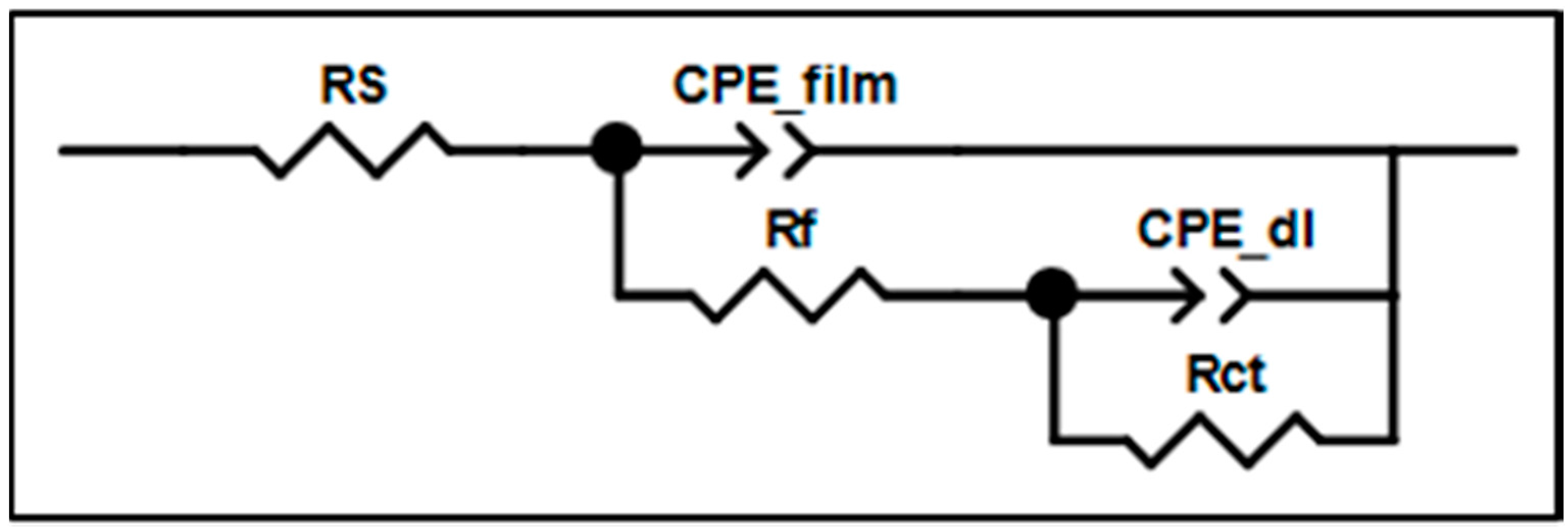
| Item/Index | Rs (Ω) | Rf (Ω) | CPE_film-T(F) | CPE_fim-P | Contact Angle (°/H2O) |
|---|---|---|---|---|---|
| HPMCP-1 | 128 | 989 | 3.49 × 10⁻⁵ | 0.40342 | 68.8 |
| HPMCP-2 | 157 | 1260 | 1.85 × 10⁻⁵ | 0.42213 | 68.6 |
| HPMCP-3 | 160 | 1368 | 1.34 × 10⁻⁵ | 0.44124 | 69.4 |
| HPMCAS-1 | 90 | 987 | 5.49 × 10⁻⁵ | 0.38172 | 63.3 |
| HPMCAS-2 | 115 | 1339 | 2.76 × 10⁻⁵ | 0.39806 | 65.0 |
| HPMCAS-3 | 120 | 1535 | 2.42 × 10⁻⁵ | 0.39101 | 63.0 |
| Item/Index | −Ecorr (mV) | Icorr (μA/cm2) | βa (mV/dec) | βc (mV/dec) |
|---|---|---|---|---|
| bare HSS | 547.5 | 26.3 | 65.4 | −159.9 |
| HPMCP-1 | 388.1 | 6.8 | 124.9 | −99.3 |
| HPMCP-2 | 294.9 | 5.2 | 112.2 | −119.9 |
| HPMCP-3 | 230.5 | 0.8 | 117.5 | −108.0 |
| HPMCAS-1 | 294.4 | 1.8 | 119.5 | −114.5 |
| HPMCAS-2 | 211.1 | 1.4 | 105.5 | −108.4 |
| HPMCAS-3 | 176.7 | 1.7 | 102.6 | −105.2 |
© 2016 by the authors; licensee MDPI, Basel, Switzerland. This article is an open access article distributed under the terms and conditions of the Creative Commons Attribution (CC-BY) license (http://creativecommons.org/licenses/by/4.0/).
Share and Cite
Shi, S.-C.; Su, C.-C. Corrosion Inhibition of High Speed Steel by Biopolymer HPMC Derivatives. Materials 2016, 9, 612. https://doi.org/10.3390/ma9080612
Shi S-C, Su C-C. Corrosion Inhibition of High Speed Steel by Biopolymer HPMC Derivatives. Materials. 2016; 9(8):612. https://doi.org/10.3390/ma9080612
Chicago/Turabian StyleShi, Shih-Chen, and Chieh-Chang Su. 2016. "Corrosion Inhibition of High Speed Steel by Biopolymer HPMC Derivatives" Materials 9, no. 8: 612. https://doi.org/10.3390/ma9080612
APA StyleShi, S.-C., & Su, C.-C. (2016). Corrosion Inhibition of High Speed Steel by Biopolymer HPMC Derivatives. Materials, 9(8), 612. https://doi.org/10.3390/ma9080612