
A New Wide-Band Double-Negative Metamaterial for C- and S-Band Applications


 , and
, and
Abstract
:1. Introduction
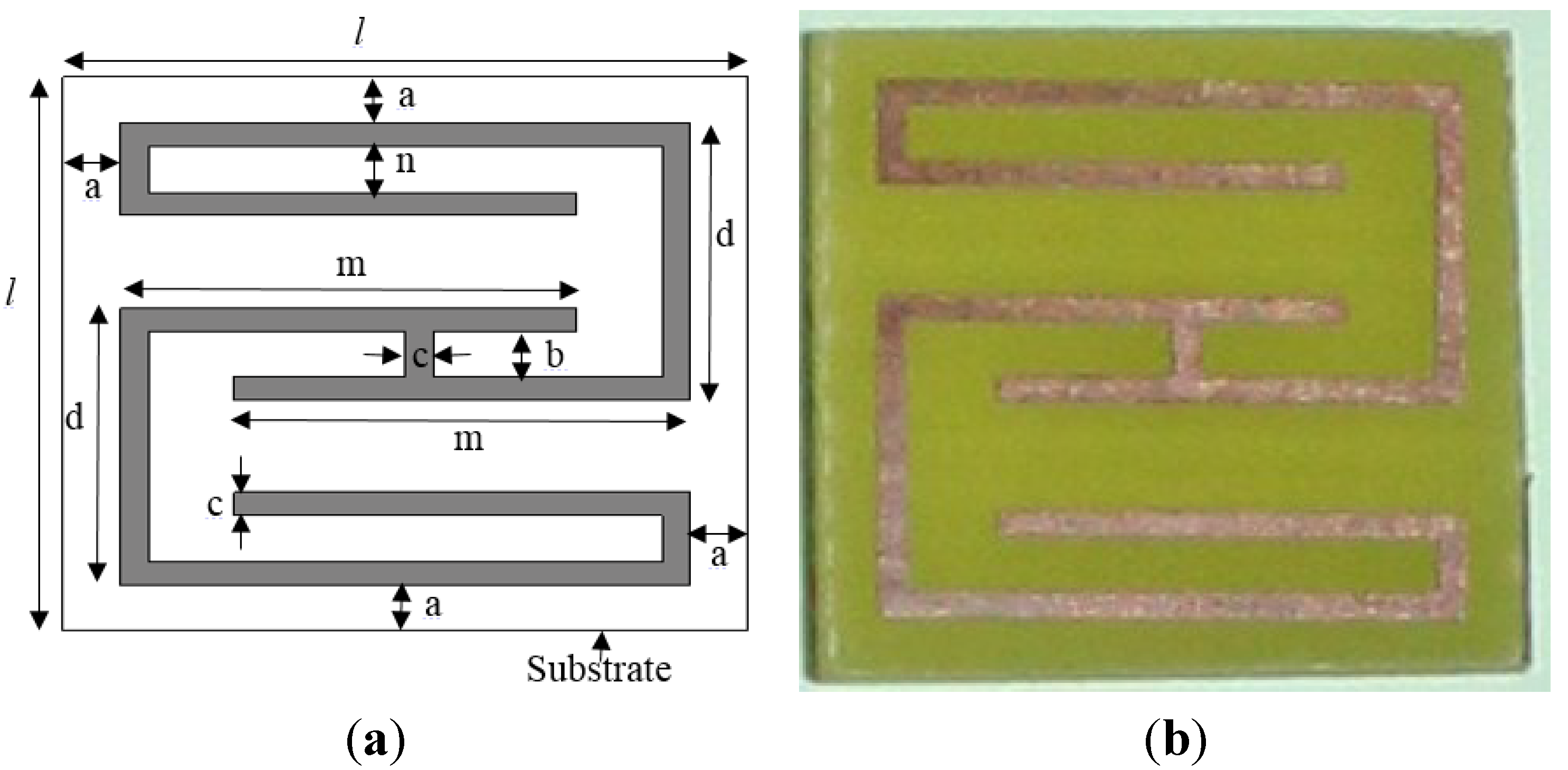
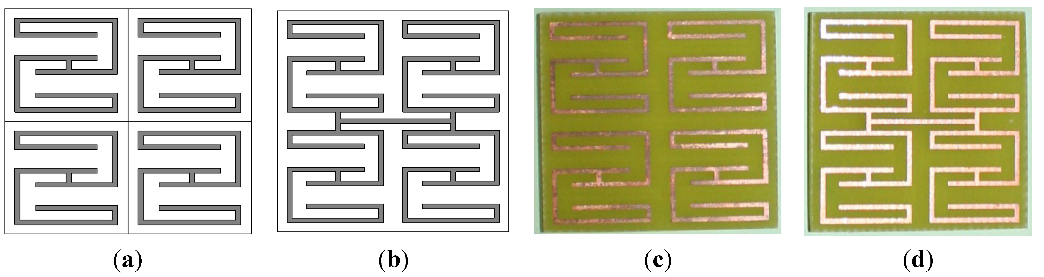
2. Metamaterial Construction


| Unit-Cell Parameters | Value (mm) | |||
|---|---|---|---|---|
| Unit Cell A | Unit Cell B | Unit Cell C | Unit Cell D | |
| a | 1 | 1 | 1 | 1 |
| b | 2 | 2 | 2 | 2 |
| c | 0.5 | 0.5 | 0.5 | 0.5 |
| d | 6 | 8 | 10 | 12 |
| l | 12 | 16 | 20 | 24 |
| m | 8 | 12 | 16 | 20 |
| n | 2.5 | 3 | 3.5 | 4 |
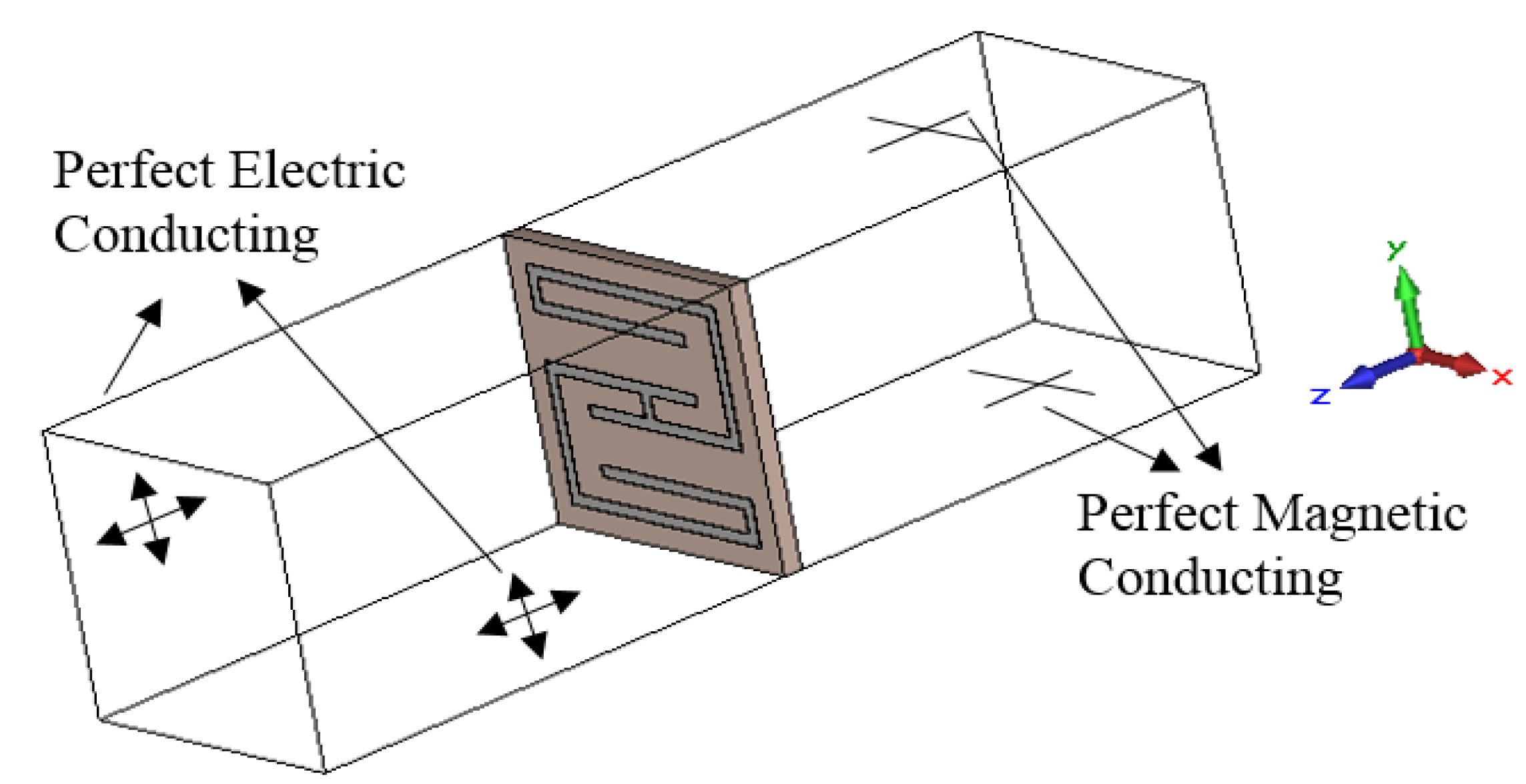
3. Numerical Methods
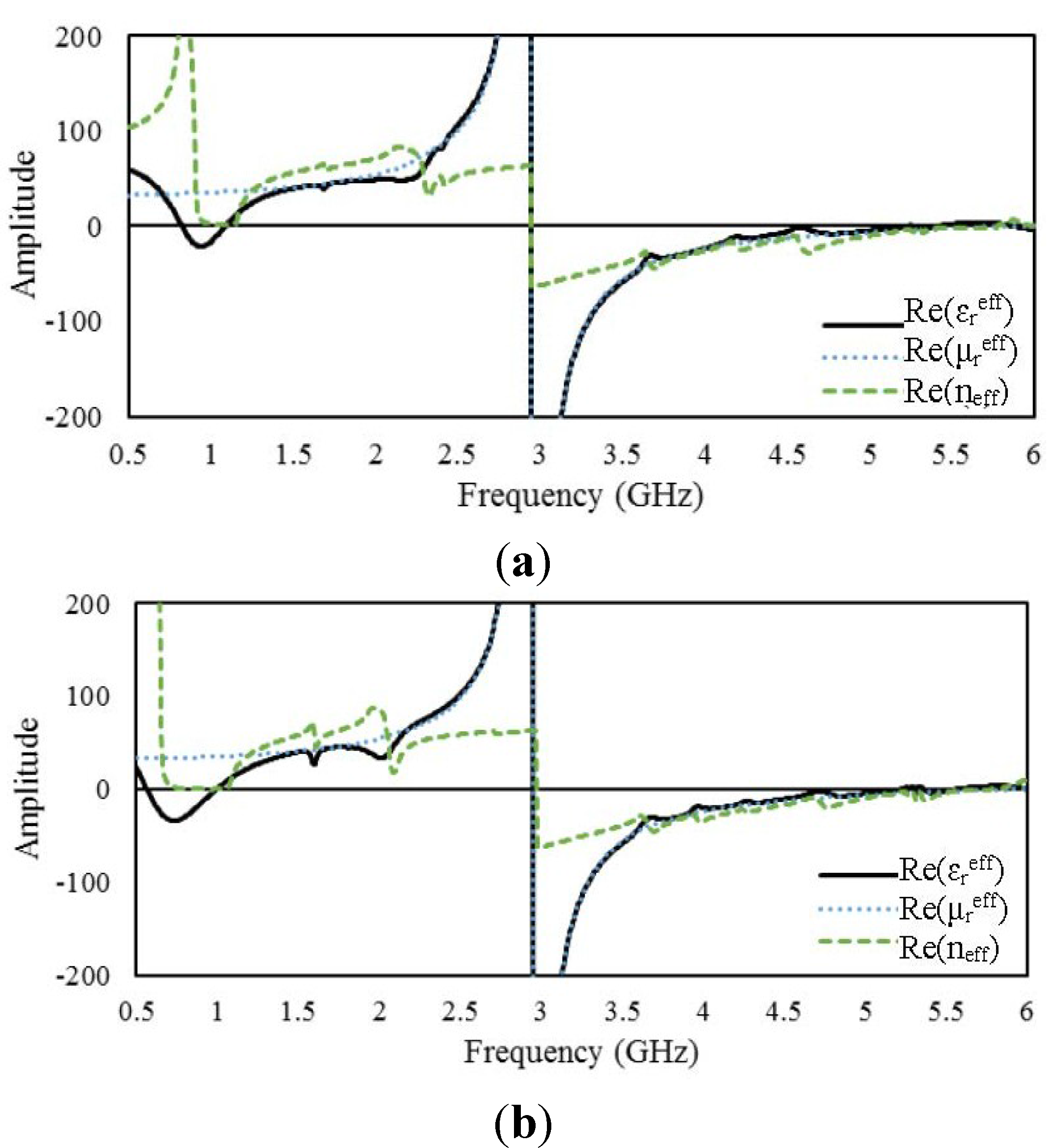
4. Results and Discussion
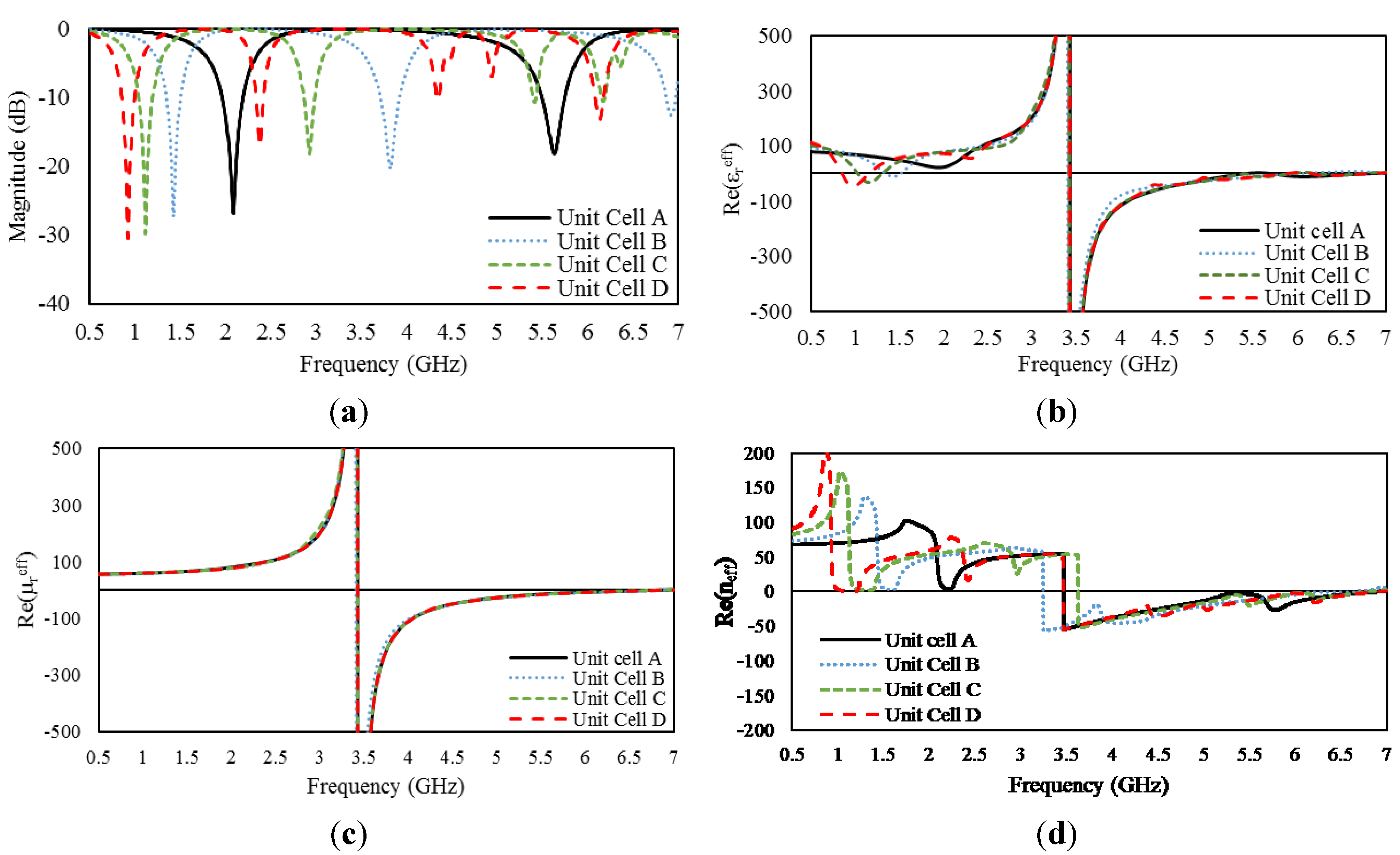
4.1. Unit Cells

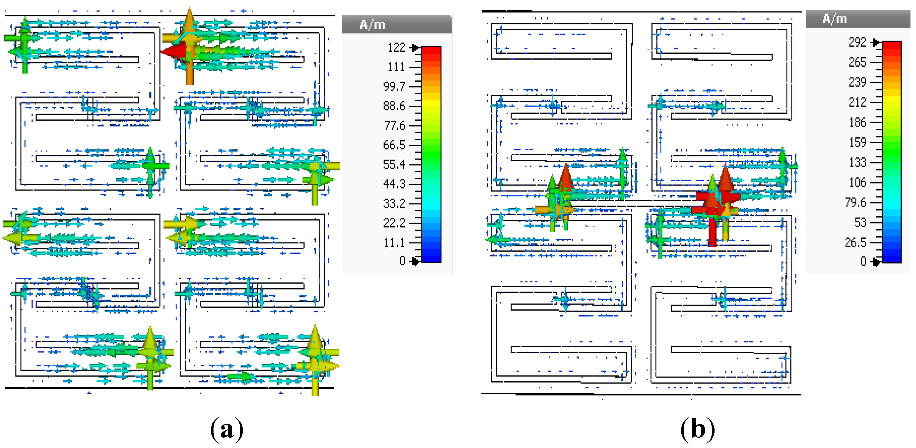
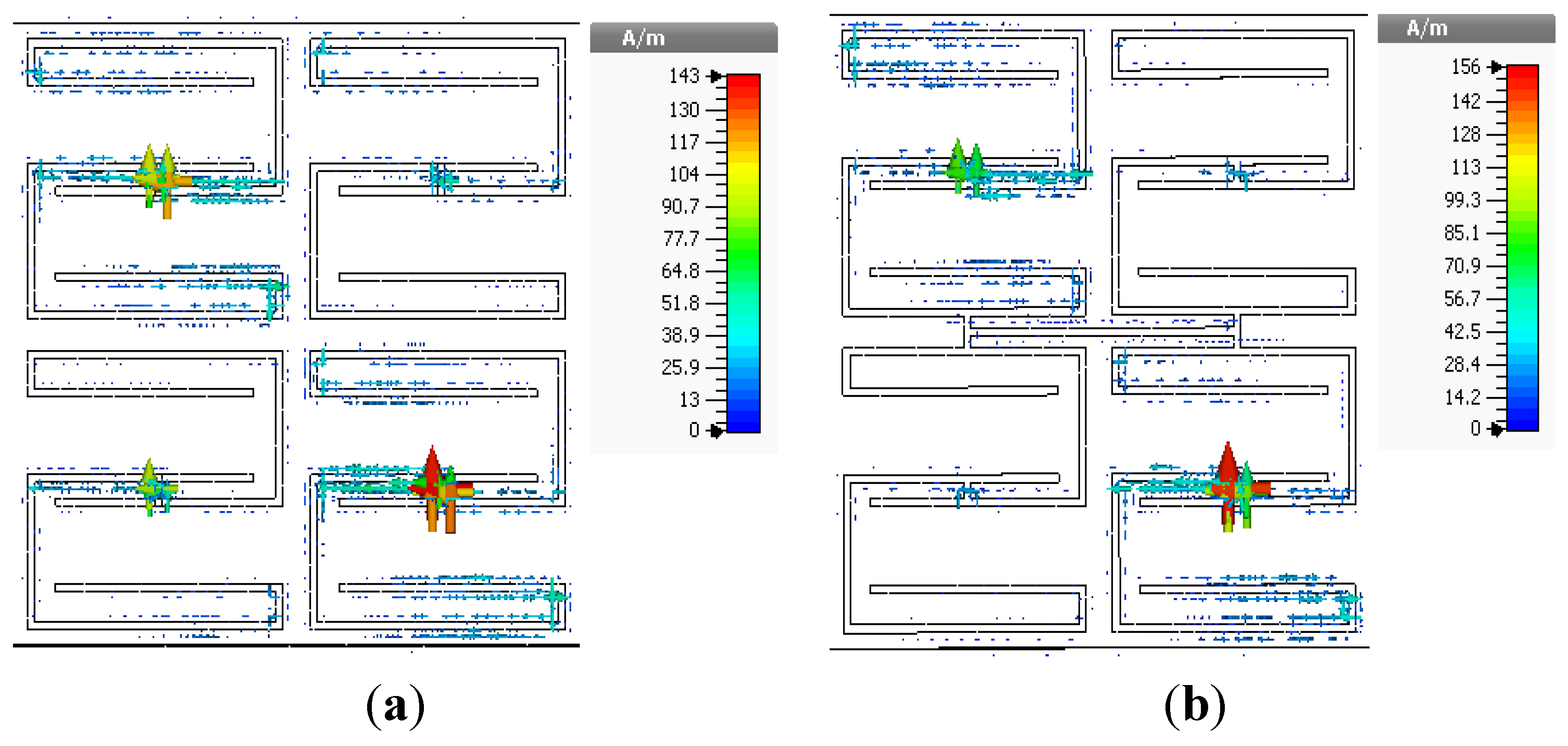
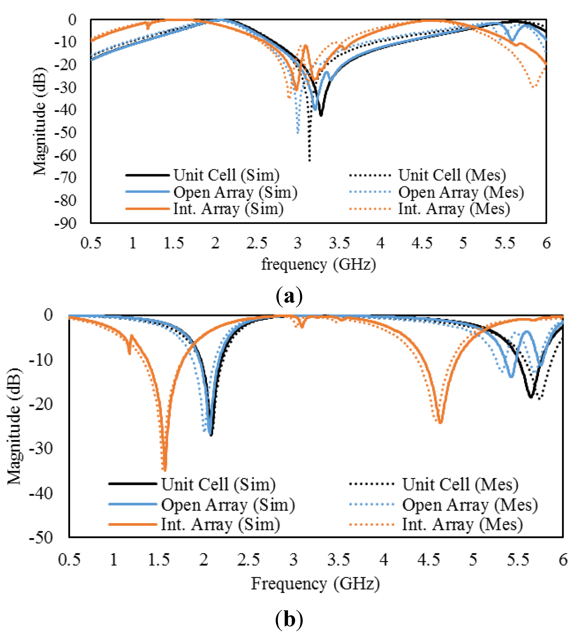
4.2. Arrays
4.2.1. 2 × 2 Arrays of Unit Cell A
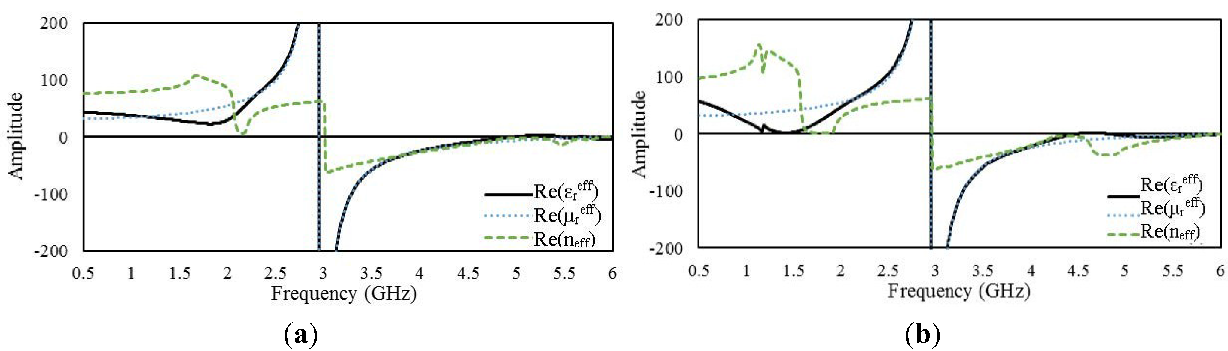

4.2.2. 2 × 2 Arrays of Unit Cell B
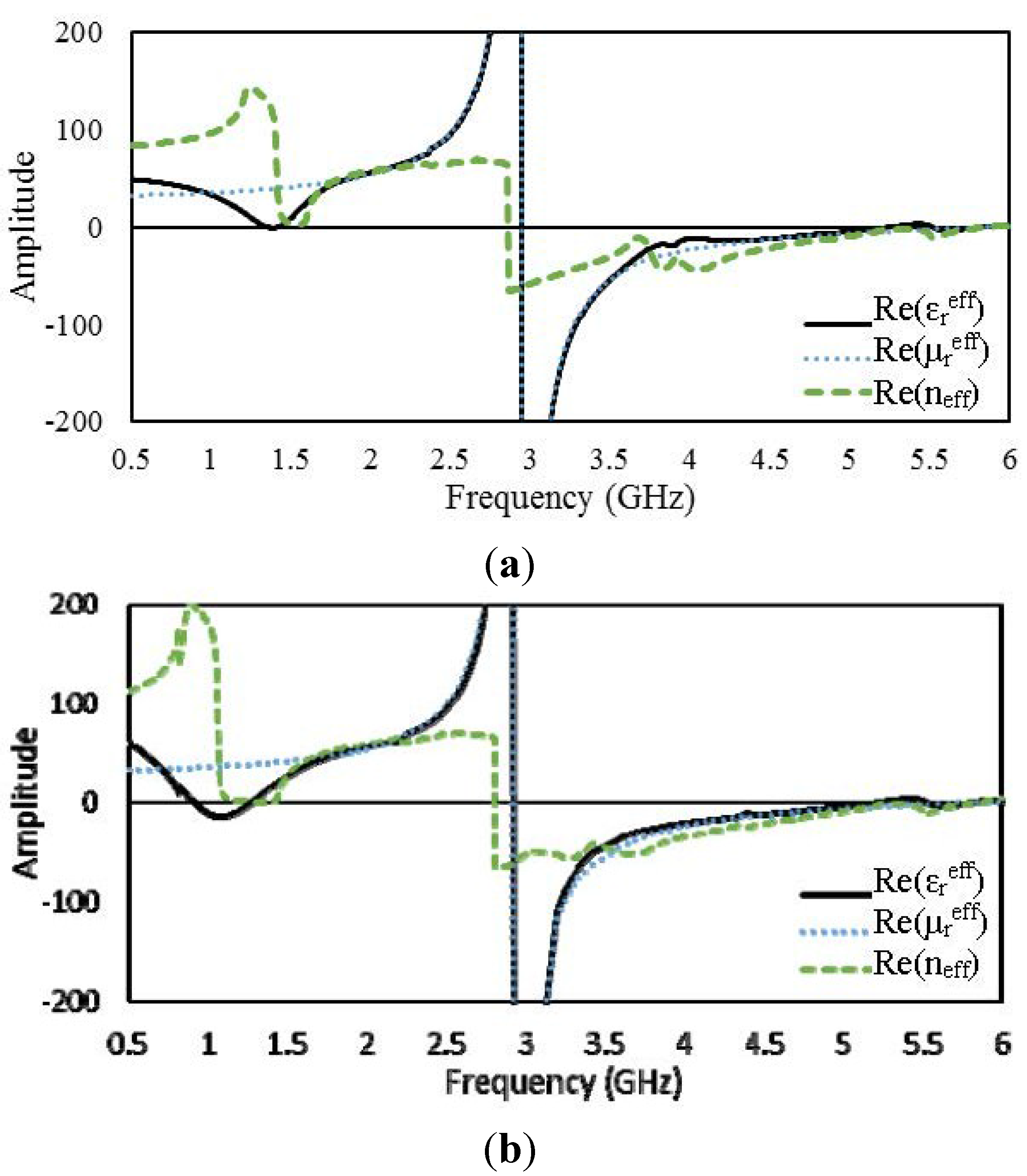

4.2.3. 2 × 2 Arrays of Unit Cell C
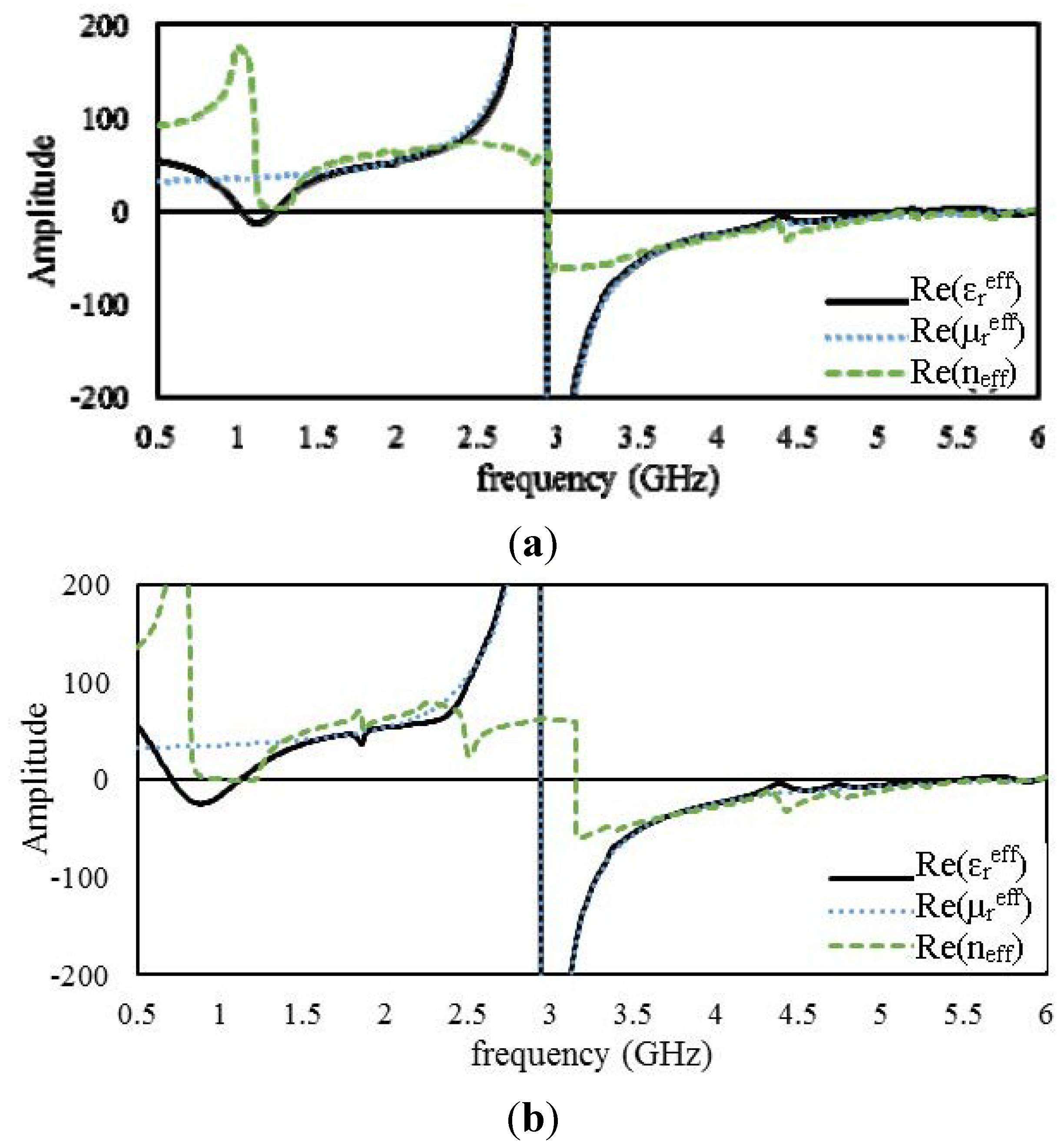

4.2.4. 2 × 2 Arrays of Unit Cell D


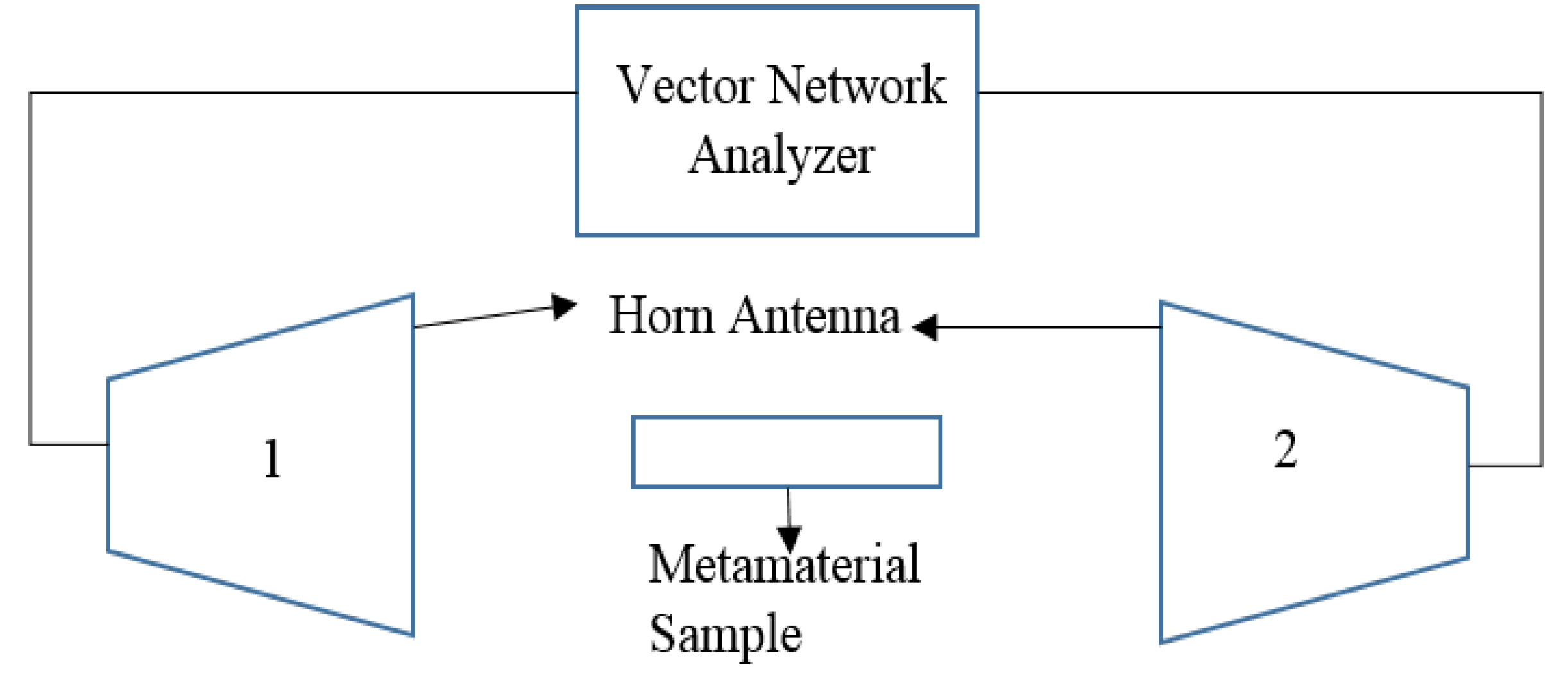
5. Experimental Validation

6. Conclusions
Acknowledgments
Author Contributions
Conflicts of Interest
References
- Ziolkowski, R.W. Design, fabrication, and testing of double negative metamaterials. IEEE Trans. Antennas Propag. 2003, 51, 1516–1529. [Google Scholar] [CrossRef]
- Hossain, M.I.; Mohammad, R.I.F.; Islam, M.T.; Hanafi, N.H.M. Application of auxiliary antenna elements for SAR reduction in the human head. In Advanced Materials Research; Trans Tech Publications Ltd.: Pfaffikon, Switzerland, 2014; Volume 974, pp. 288–292. [Google Scholar]
- Huang, X.Q.; Lai, Y.; Hang, Z.H.; Chan, C.T. Dirac cones induced by accidental degeneracy in photonic crystal and zero-refractive-index materials. Nat. Mater. 2011, 10, 582–586. [Google Scholar] [CrossRef] [PubMed]
- Ziolkowski, R.W. Propagation in and scattering from a matched metamaterial having a zero index of refraction. Phys. Rev. E 2004, 70. [Google Scholar] [CrossRef]
- Cui, T.J.; Smith, D.; Liu, R. Metamaterials: Theory, Design, and Applications; Springer: Berlin, Germany, 2009. [Google Scholar]
- Karamanos, T.D.; Dimitriadis, A.I.; Kantartzis, N.V. Compact double-negative metamaterials based on electric and magnetic resonators. Antennas Wirel. Propag. Lett. IEEE 2012, 11, 480–483. [Google Scholar] [CrossRef]
- Viktor, G.; Veselago, P.N.L. The electrodynamics of substances with simultaneously negative values of ɛ and μ. Sov. Phys. Uspekhi 1968, 10, 509–514. [Google Scholar] [CrossRef]
- Smith, D.R.; Padilla, W.J.; Vier, D.C.; Nemat-Nasser, S.C.; Schultz, S. Composite medium with simultaneously negative permeability and permittivity. Phys. Rev. Lett. 2000, 84. [Google Scholar] [CrossRef] [PubMed]
- Grbic, A.; Eleftheriades, G.V. Overcoming the diffraction limit with a planar left-handed transmission-line lens. Phys. Rev. Lett. 2004, 92. [Google Scholar] [CrossRef] [PubMed]
- Puentes, M.; Maasch, M.; Schussler, M.; Jakoby, R. Frequency multiplexed 2-dimensional sensor array based on split-ring resonators for organic tissue analysis. IEEE Trans. Microw. Theory Tech. 2012, 60, 1720–1727. [Google Scholar] [CrossRef]
- Schurig, D.; Mock, J.J.; Justice, B.J.; Cummer, S.A.; Pendry, J.B.; Starr, A.F.; Smith, D.R. Metamaterial electromagnetic cloak at microwave frequencies. Science 2006, 314, 977–980. [Google Scholar] [CrossRef] [PubMed]
- Ullah, M.H.; Islam, M.T.; Faruque, M.R.I. A near-zero refractive index meta-surface structure for antenna performance improvement. Materials 2013, 6, 5058–5068. [Google Scholar] [CrossRef]
- Wu, B.-I.; Wang, W.; Pacheco, J.; Chen, X.; Grzegorczyk, T.M.; Kong, J.A. A study of using metamaterials as antenna substrate to enhance gain. Prog. Electromagn. Res. 2005, 51, 295–328. [Google Scholar] [CrossRef]
- Faruque, M.R.I.; Islam, M.T.; Ali, M.A.M. A new design of metamaterials for SAR reduction. Meas. Sci. Rev. 2013, 13, 70–74. [Google Scholar] [CrossRef]
- Landy, N.I.; Bingham, C.M.; Tyler, T.; Jokerst, N.; Smith, D.R.; Padilla, W.J. Design, theory, and measurement of a polarization-insensitive absorber for terahertz imaging. Phys. Rev. B 2009, 79. [Google Scholar] [CrossRef]
- Chen, H.; Ran, L.; Huangfu, J.; Zhang, X.; Chen, K.; Grzegorczyk, T.M.; Kong, J.A. Left-handed materials composed of only S-shaped resonators. Phys. Rev. E 2004, 70. [Google Scholar] [CrossRef]
- Joshi, J.G.; Pattnaik, S.S.; Devi, S. Metamaterial embedded wearable rectangular microstrip patch antenna. Int. J. Antennas Propag. 2012, 2012. [Google Scholar] [CrossRef]
- Attia, H.; Bait-Suwailam, M.M.; Ramahi, O.M.; Electromagnet, A. Enhanced gain planar inverted-F antenna with metamaterial superstrate for UMTS applications. PIERS Online 2010, 6, 585–588. [Google Scholar] [CrossRef]
- Islam, S.S.; Faruque, M.R.I.; Islam, M.T. The design and analysis of a novel Split-H-Shaped metamaterial for multi-band microwave applications. Materials 2014, 7, 4994–5011. [Google Scholar] [CrossRef]
- Nicolson, A.M.; Ross, G.F. Measurement of the intrinsic properties of materials by time-domain techniques. IEEE Trans. Instrum. Meas. 1970, 19, 377–382. [Google Scholar] [CrossRef]
- Barroso, J.J.; de Paula, A.L. Retrieval of permittivity and permeability of homogeneous materials from scattering parameters. J. Electromagn. Waves Appl. 2010, 24, 1563–1574. [Google Scholar] [CrossRef]
- Schurig, D.; Mock, J.J.; Smith, D.R. Electric-field-coupled resonators for negative permittivity metamaterials. Appl. Phys. Lett. 2006, 88. [Google Scholar] [CrossRef]
- Liu, R.; Degiron, A.; Mock, J.J.; Smith, D.R. Negative index material composed of electric and magnetic resonators. Appl. Phys. Lett. 2007, 90. [Google Scholar] [CrossRef]
- Li, D.; Szabo, Z.; Qing, X.; Li, E.-P.; Chen, Z.N. A high gain antenna with an optimized metamaterial inspired superstrate. IEEE Trans. Antennas Propag. 2012, 60, 6018–6023. [Google Scholar] [CrossRef]
© 2014 by the authors; licensee MDPI, Basel, Switzerland. This article is an open access article distributed under the terms and conditions of the Creative Commons Attribution license (http://creativecommons.org/licenses/by/4.0/).
Share and Cite
Hossain, M.I.; Faruque, M.R.I.; Islam, M.T.; Ullah, M.H. A New Wide-Band Double-Negative Metamaterial for C- and S-Band Applications. Materials 2015, 8, 57-71. https://doi.org/10.3390/ma8010057
Hossain MI, Faruque MRI, Islam MT, Ullah MH. A New Wide-Band Double-Negative Metamaterial for C- and S-Band Applications. Materials. 2015; 8(1):57-71. https://doi.org/10.3390/ma8010057
Chicago/Turabian StyleHossain, Md Ikbal, Mohammad Rashed Iqbal Faruque, Mohammad Tariqul Islam, and Mohammad Habib Ullah. 2015. "A New Wide-Band Double-Negative Metamaterial for C- and S-Band Applications" Materials 8, no. 1: 57-71. https://doi.org/10.3390/ma8010057
APA StyleHossain, M. I., Faruque, M. R. I., Islam, M. T., & Ullah, M. H. (2015). A New Wide-Band Double-Negative Metamaterial for C- and S-Band Applications. Materials, 8(1), 57-71. https://doi.org/10.3390/ma8010057