Nanoscale Hollow Spheres: Microemulsion-Based Synthesis, Structural Characterization and Container-Type Functionality

Abstract
1. Introduction
- (1)
- Based on equilibrated, thermally stable micelles, the microemulsion approach can be widely modified by adjusting the type and amount of polar/nonpolar phase and surfactants. This allows for fine-tuning the micelle diameter—and as an immediate consequence—controlling the diameter of the resulting hollow spheres.
- (2)
- The possibility to establish water-in-oil-(w/o)—as well as oil-in-water-(o/w) microemulsions—increases the experimental flexibility of the approach even further, since polar, water-soluble starting materials as well as non-polar ones can be applied according to the specific needs and restrictions of each synthesis.
- (3)
- A wide variety of nanoscale hollow sphere compositions is accessible, ranging from elemental metals to metal oxides, metal sulfides or organic-inorganic hybrids.
- (4)
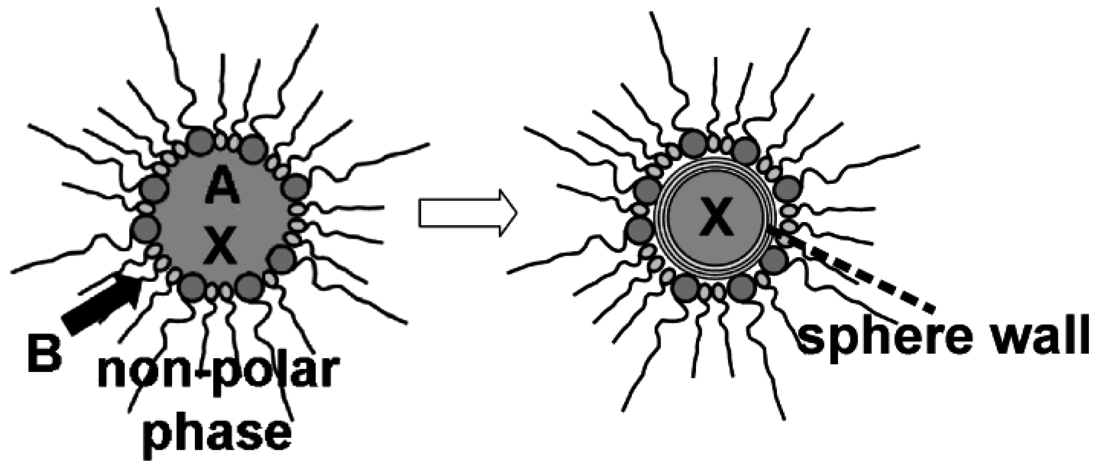
- While establishing the sphere wall of the hollow shperes, all compounds dissolved inside the micelle are encapsulated. Accordingly, the use of microemulsions gives direct access to container-type functionalities.
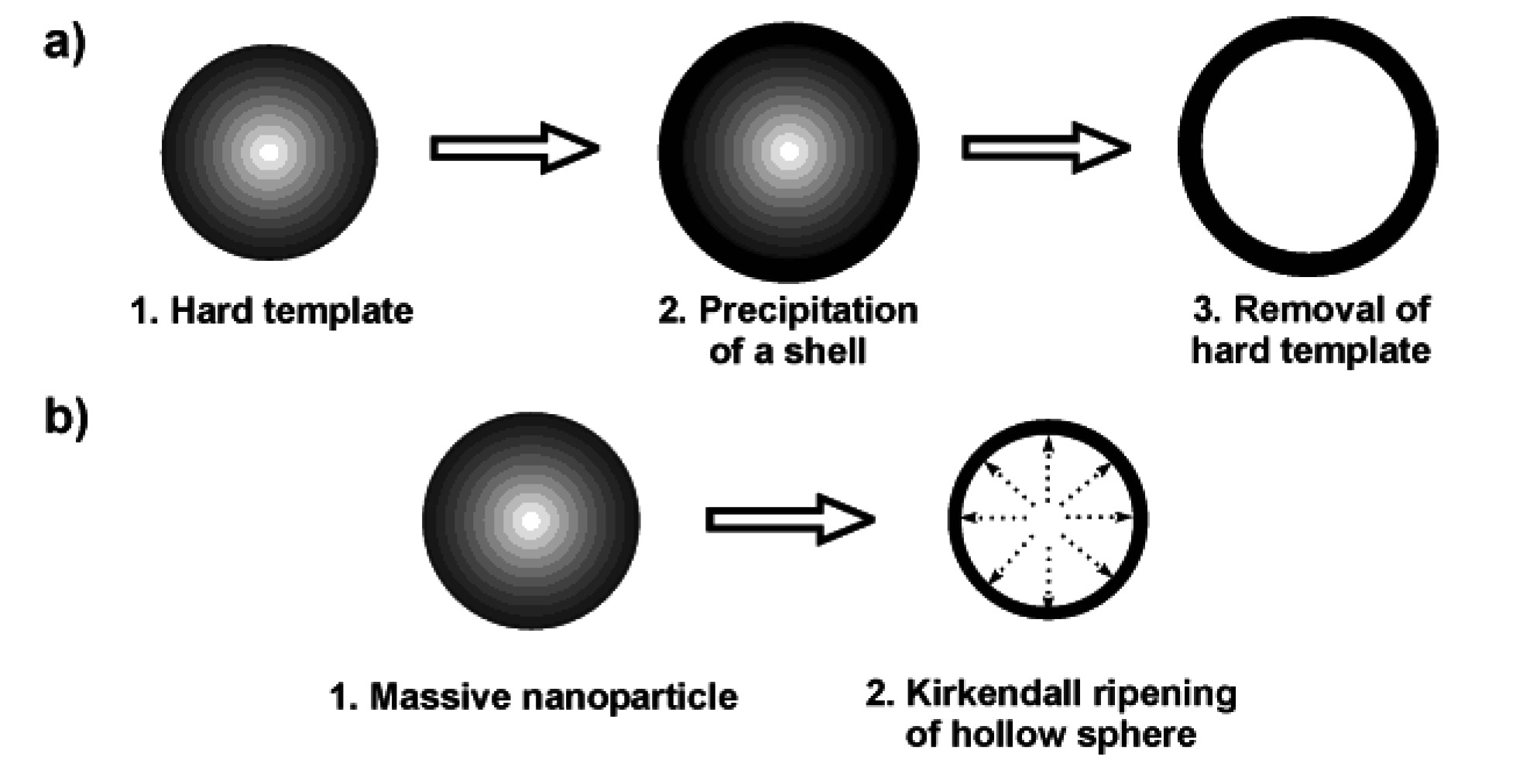
2. Strategies to Prepare Nanoscale Hollow Spheres
2.1. Techniques based on hard templates

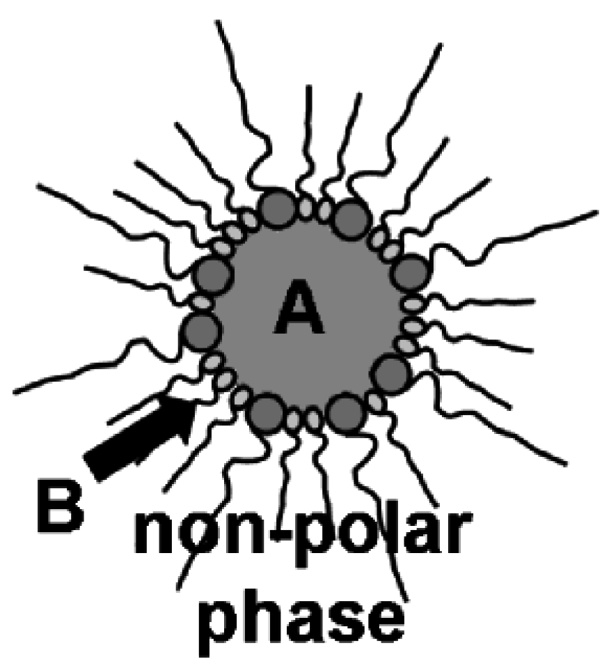
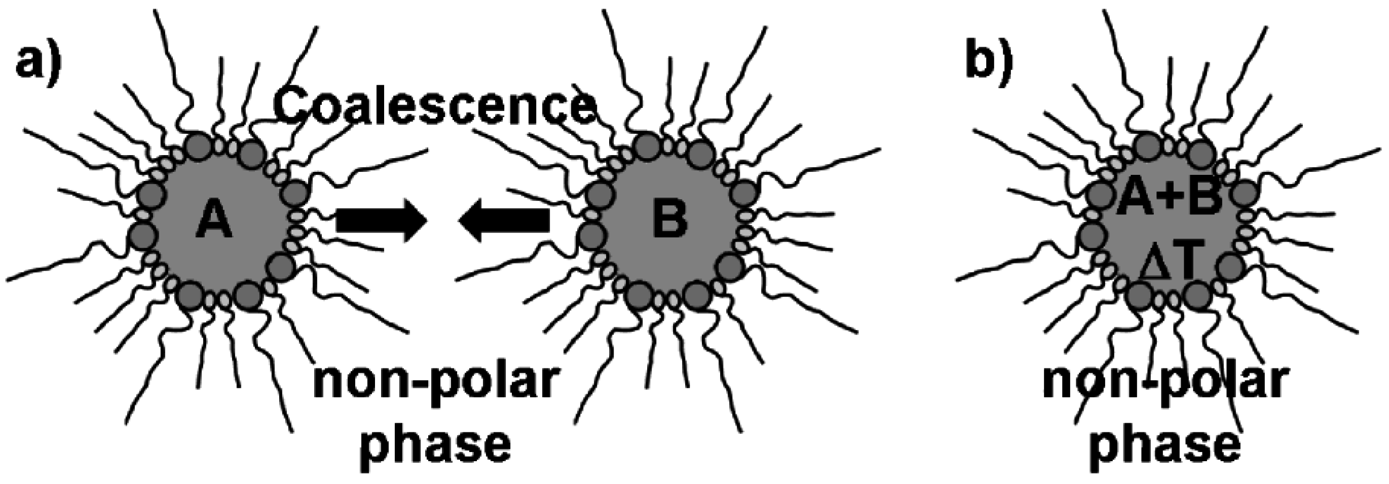
2.2. Microemulsion techniques: some general considerations

2.3. Nanoscale hollow spheres via the microemulsion approach

| Type of hollow sphere | Starting material for non-polar oil-phase | Starting material for polar water-phase |
|---|---|---|
| Au | C12H25SH | KAuCl4 |
| Ag | [Ag(PPh3)]4NO3 | NaBH4 |
| ZnO | Zn(Cp*)2 | H2O |
| TiO2 | TiCl4 | H2O |
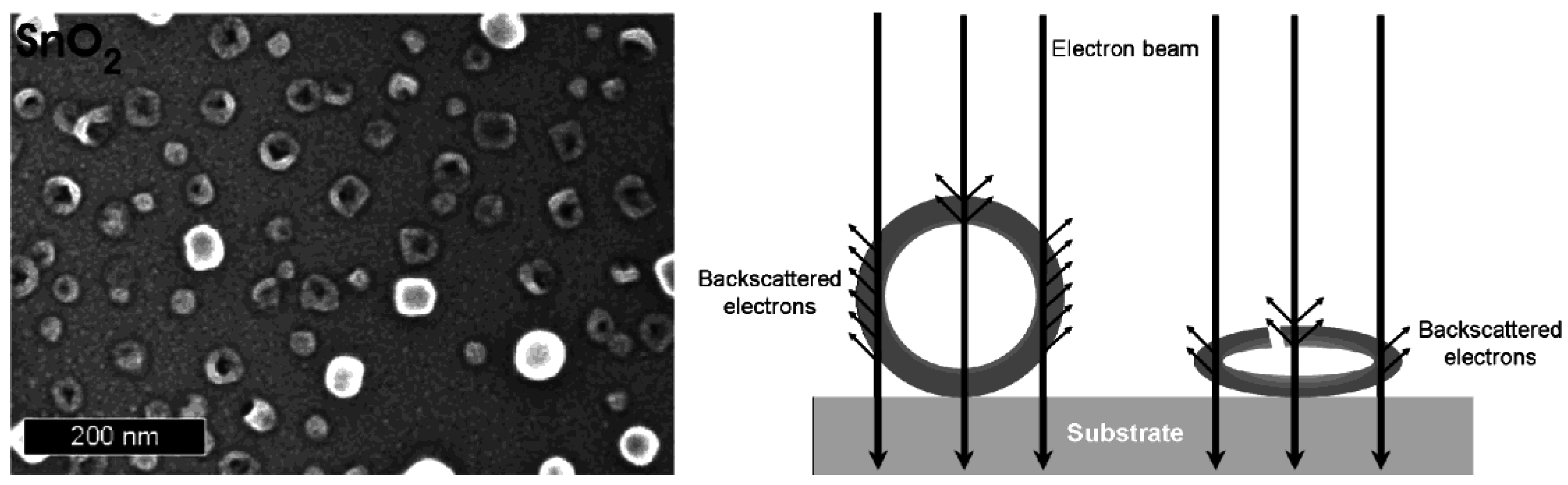
| SnO2 | Sn(i-OC3H7)4 | H2O |
| AlO(OH) | Al(t-OC4H9)3 | H2O |
| La(OH)3 | La(Cp)3 | 0.1 M KF |
| Cu2S | [Cu(PPh3)2]Cl | (NH2)2CS |
| CuS | Cu(C9H17COO)2 | (NH2)2CS |
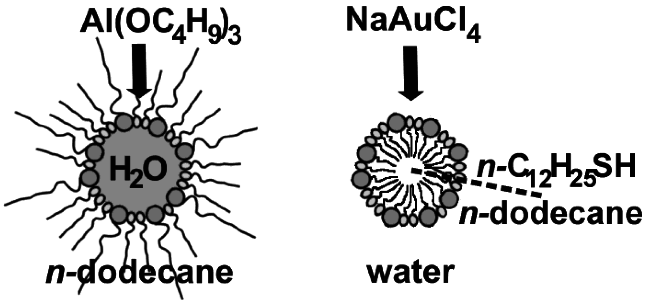
2.4. w/o- and o/w-Microemulsions for hollow sphere generation

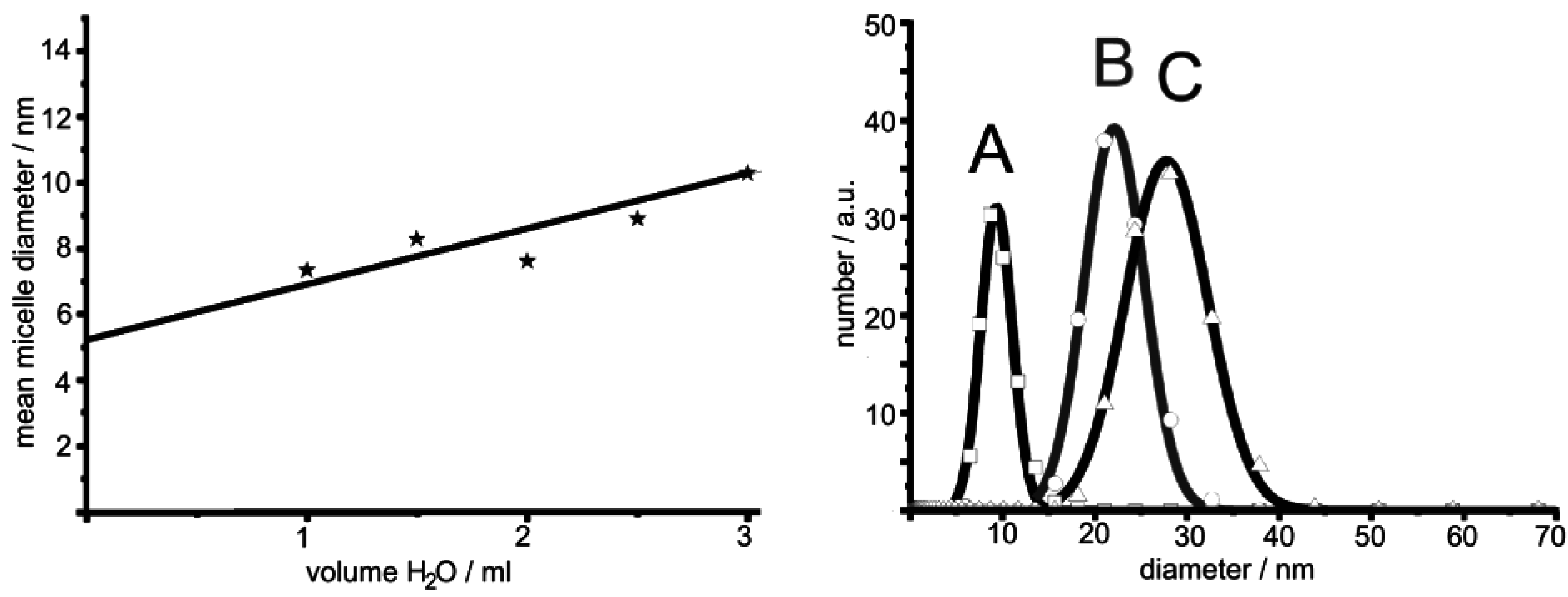
2.5. Control of outer diameter and cavity size


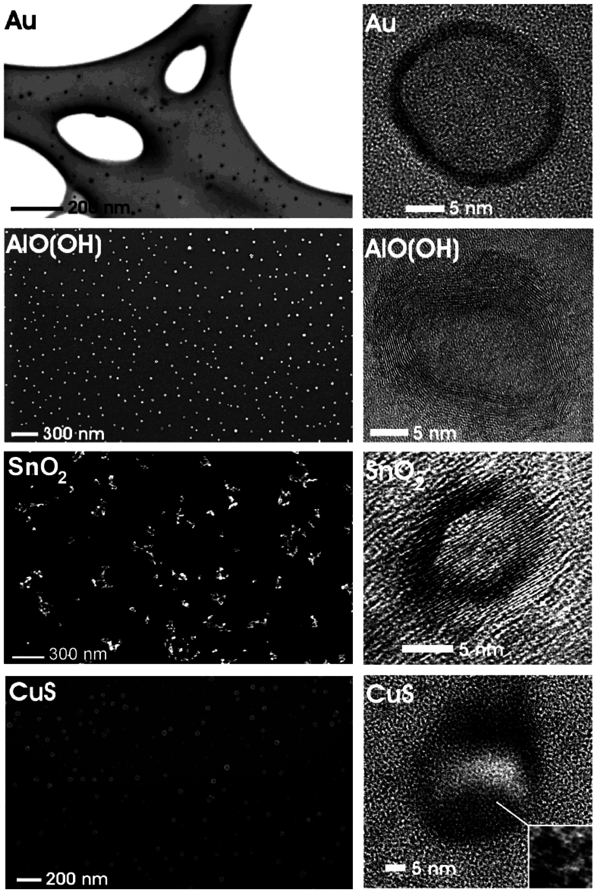
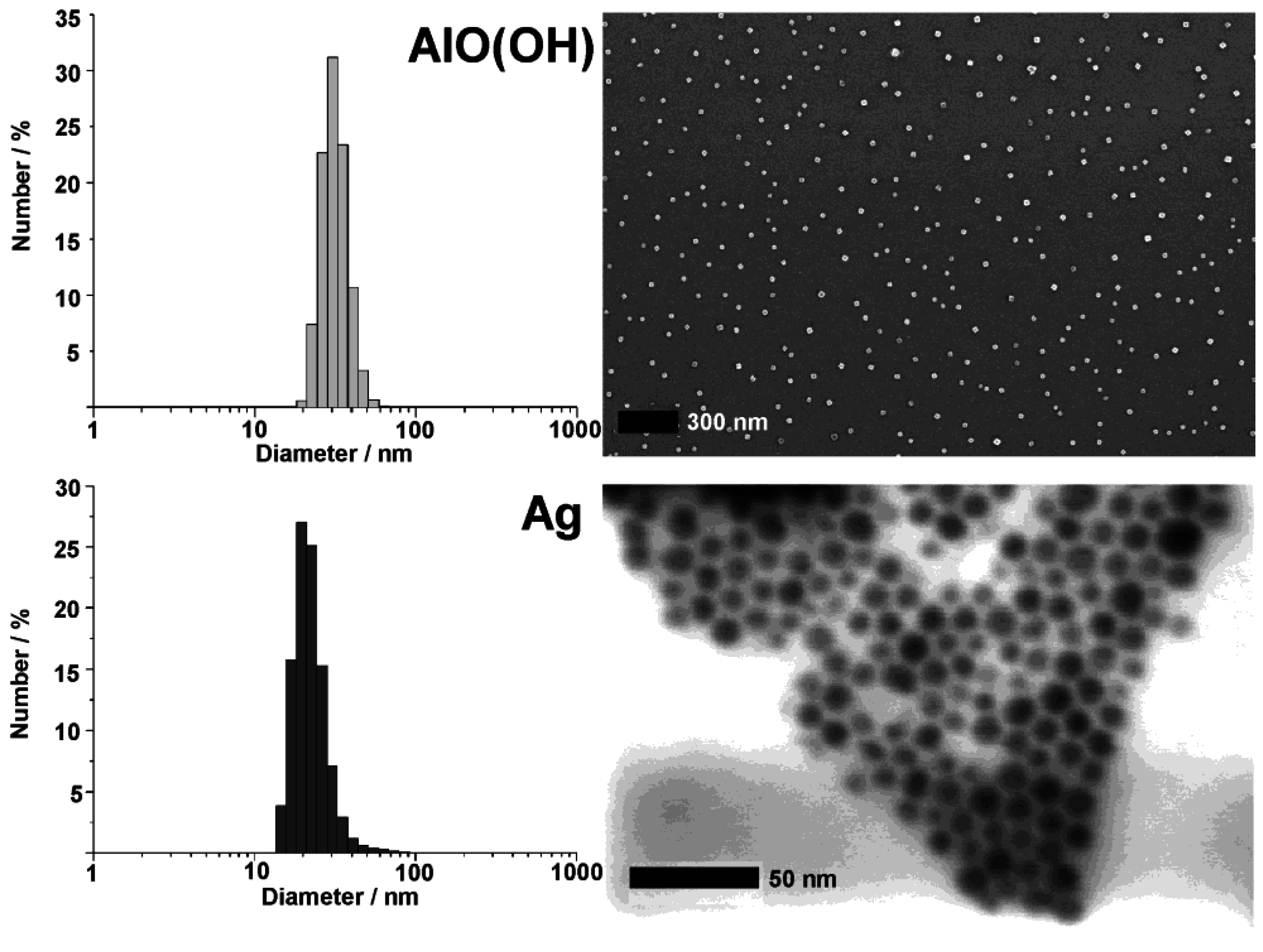
3. Morphological Characterization
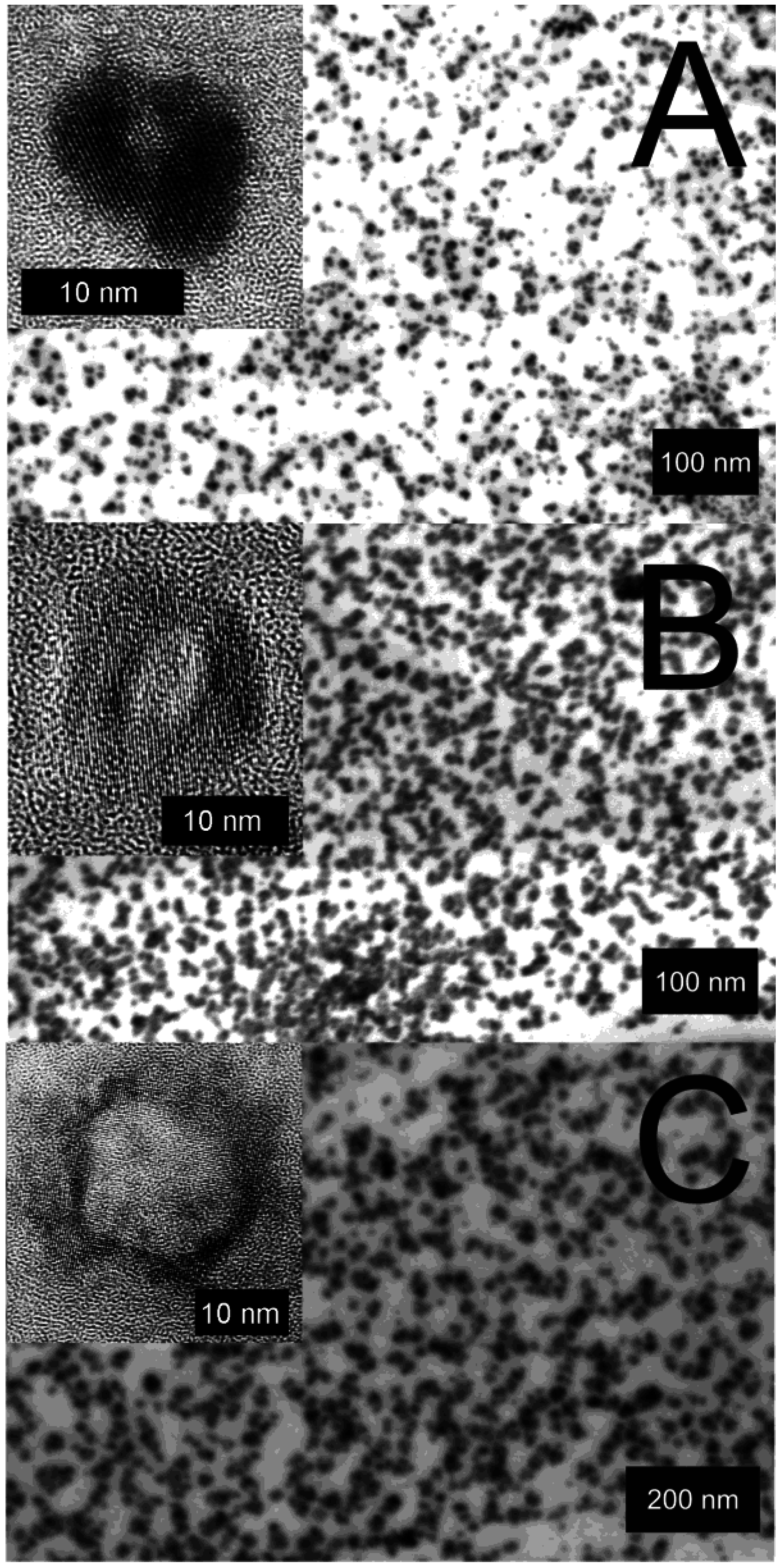
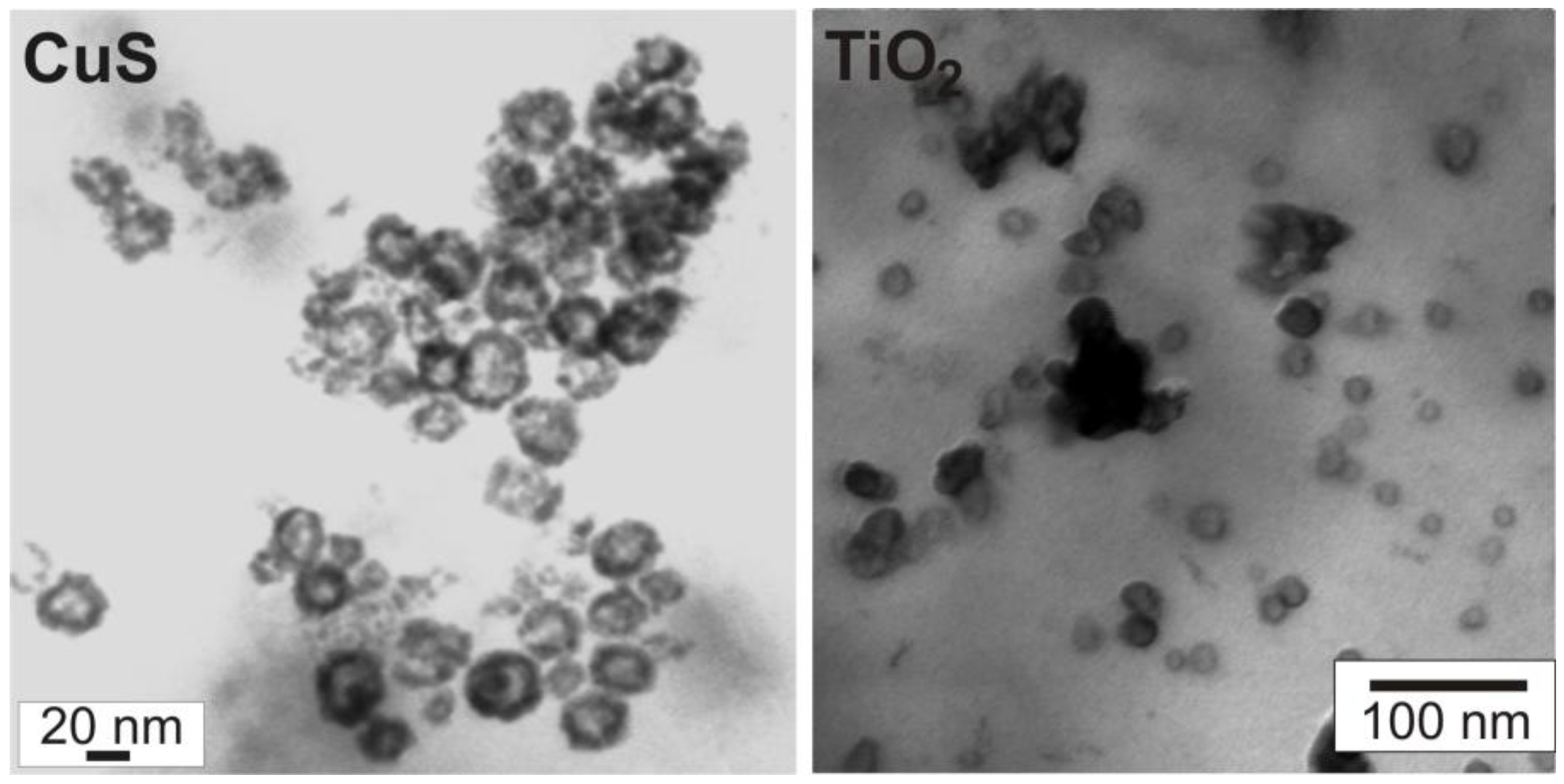
3.1. Size and size distribution
| Type of hollow sphere | Mean outer diameter deduced from: | Mean diameter of inner cavity deduced from: | ||
|---|---|---|---|---|
| DLS | SEM/TEM | STEM/HRTEM | ||
| Au | 27 ± 4 | 25 ± 3 | ~20 | |
| Ag | 18 ± 3 | 18 ± 3 | ~13 | |
| ZnO | 22 ± 4 | 20 ± 4 | ~15 | |
| TiO2 | 51 ± 6 | 48 ± 5 | ~30 | |
| SnO2 | 22 ± 3 | 20 ± 3 | ~18 | |
| AlO(OH) | 33 ± 5 | 30 ± 5 | ~22 | |
| La(OH)3 | 9 ± 4 | 11 ± 3 | ~2 | |
| 22 ± 6 | 20 ± 5 | ~7 | ||
| 28 ± 9 | 30 ± 5 | ~17 | ||
| Cu2S | 41 ± 6 | 35 ± 5 | ~20 | |
| CuS | 25 ± 4 | 25 ± 6 | ~27 | |
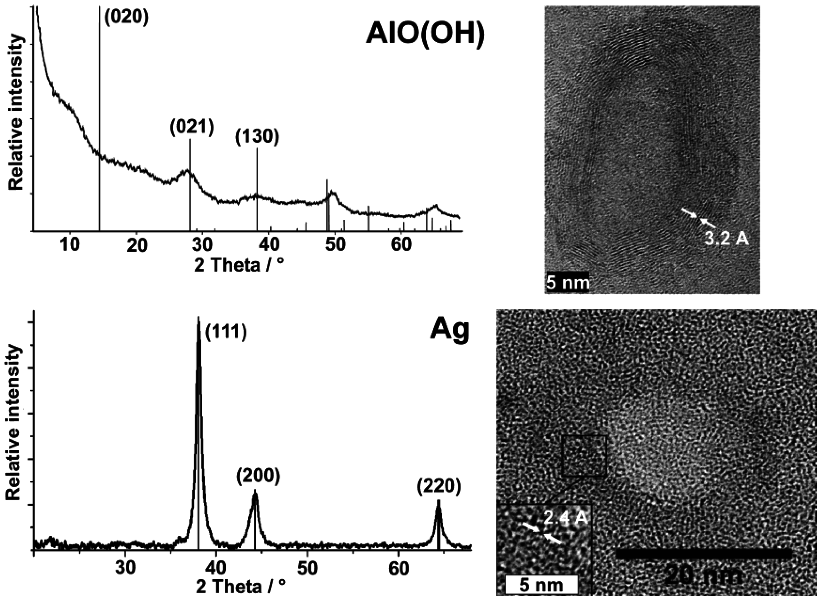
| Type of hollow sphere | Wall thickness deduced from: HRTEM [nm] | Observed lattice fringes along the sphere wall as given by HRTEM [Å] |
|---|---|---|
| Au | 2−3 | 2.0 (200); reference with 2.04 |
| Ag | 3−5 | 2.4 (111); reference with 2.36 |
| ZnO | 4−6 | n.d. |
| TiO2 (anatase) | 10−15 | 3.4 (101); reference with 3.52 |
| SnO2 | 3−5 | 3.3 (110); reference with 3.35 |
| AlO(OH) (boehmite) | 5−7 | 3.2 (120); reference with 3.17 |
| La(OH)3 | 4−6 | 2.8 (200); reference with 2.83 |
| 3.2 (101); reference with 3.19 | ||
| Cu2S (chalcocite) | 4–8 | 3.3 (341); reference with 3.37 |
| 3.1 (245); reference with 3.18 | ||
| CuS (covellite) | 5−11 | 2.0 (110); reference with 1.90 |
3.2. Crystallinity and chemical composition
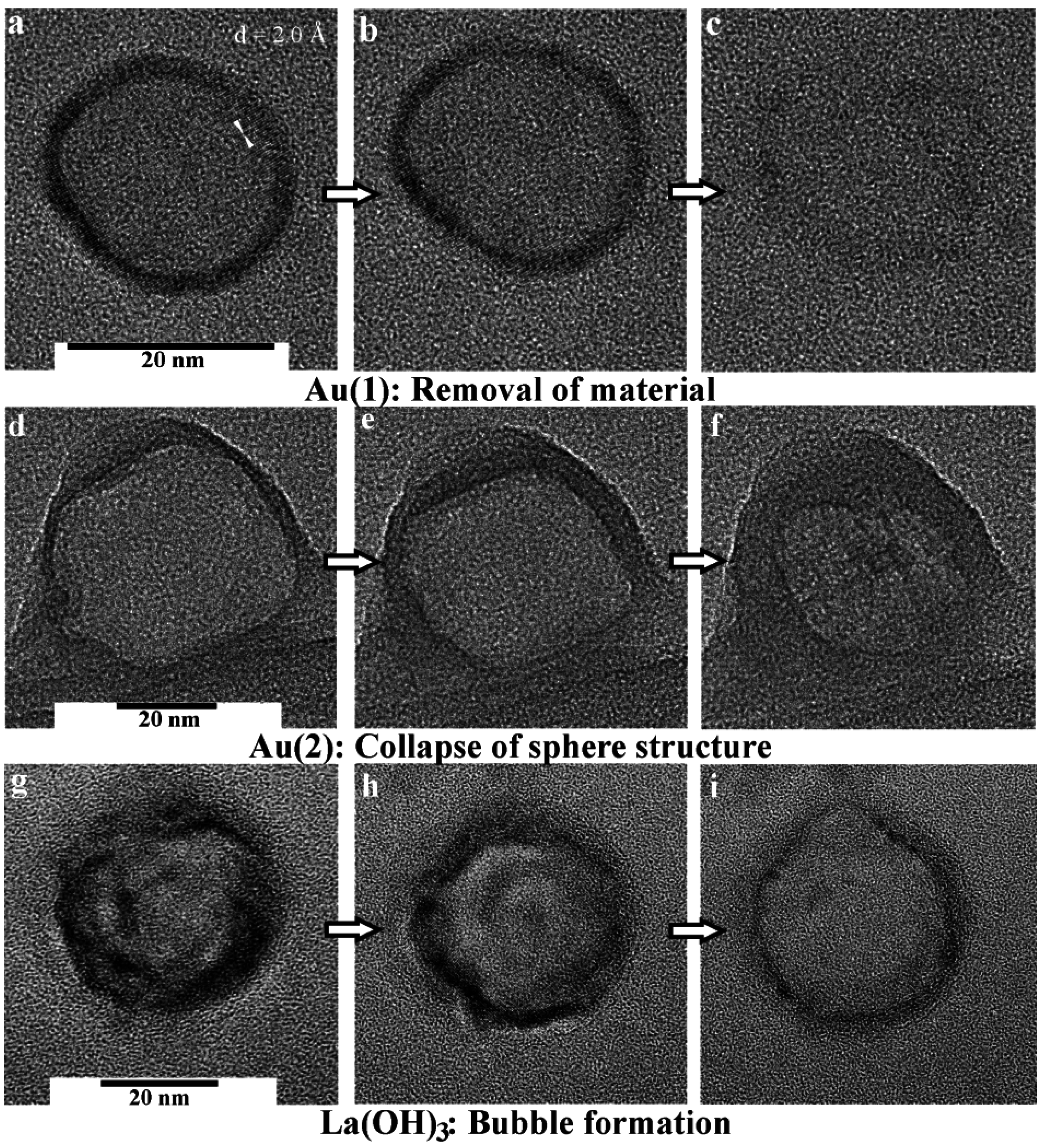
3.3. Stability at elevated temperatures and under electron bombardment

4. Container-Type Functionalities

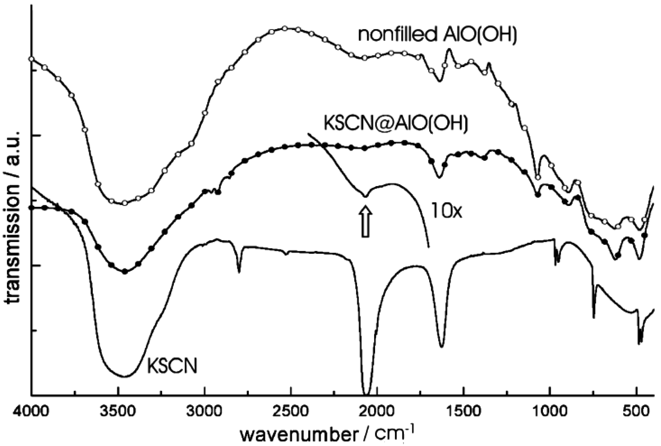
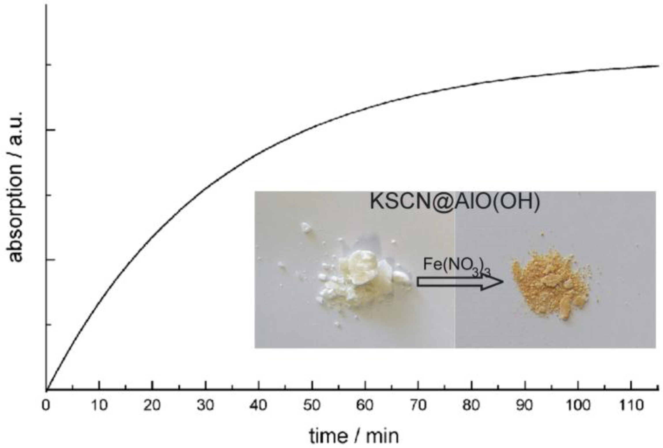
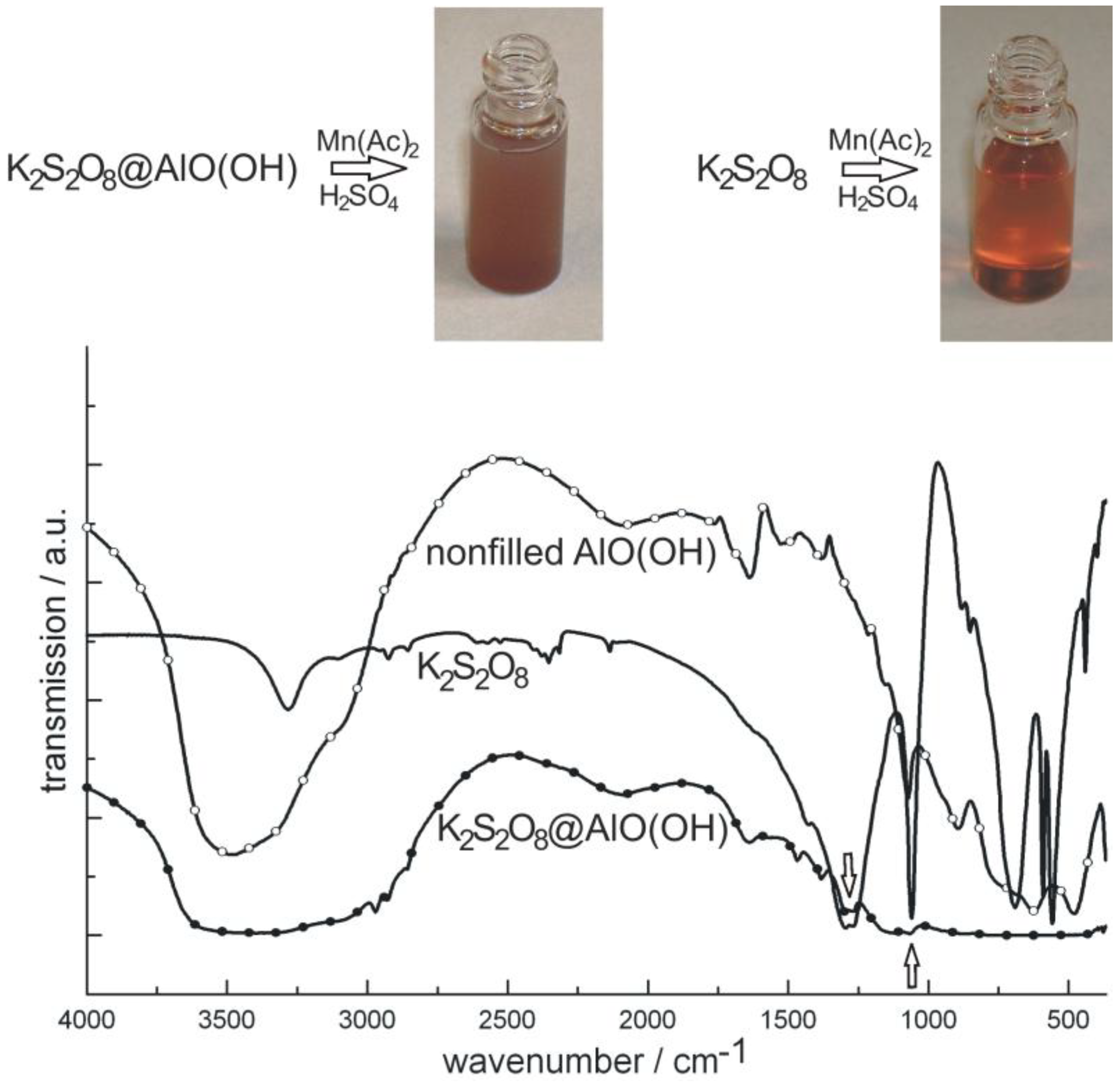
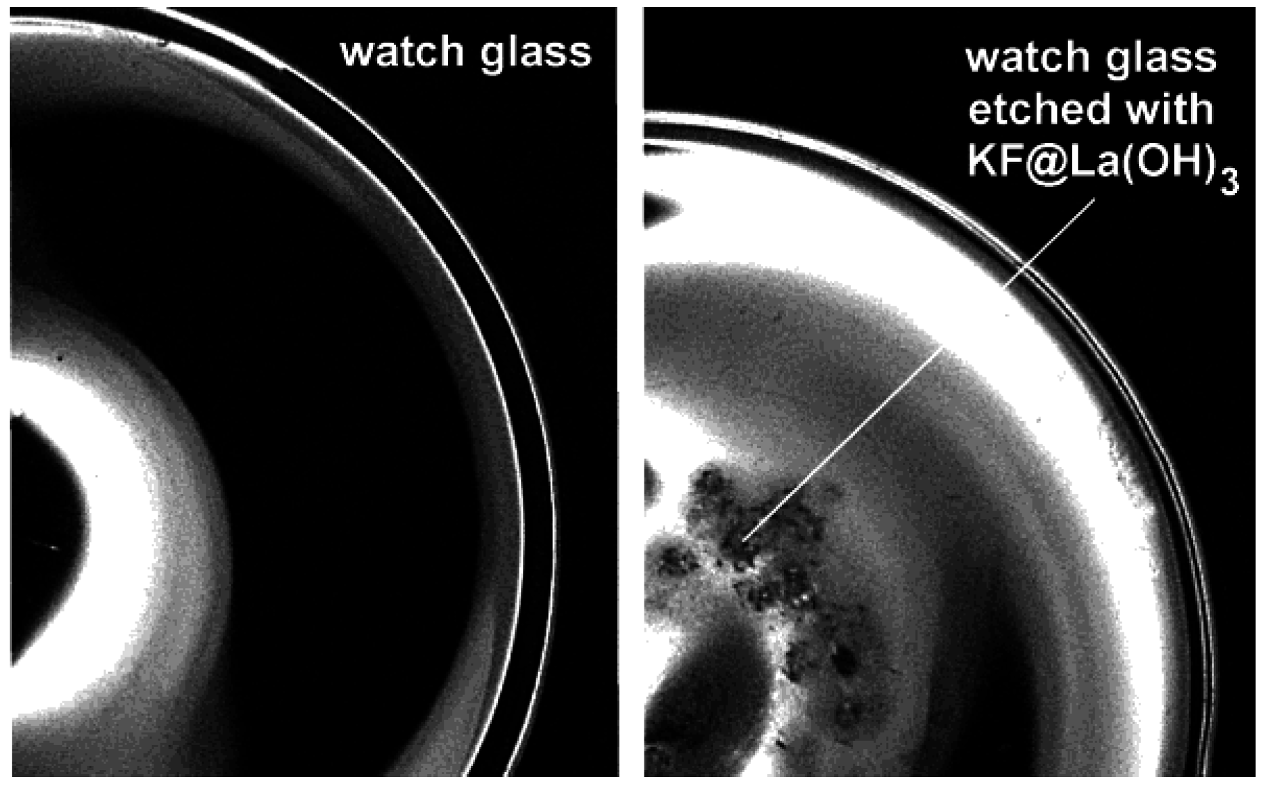
4.1. Encapsulation of inorganic salts
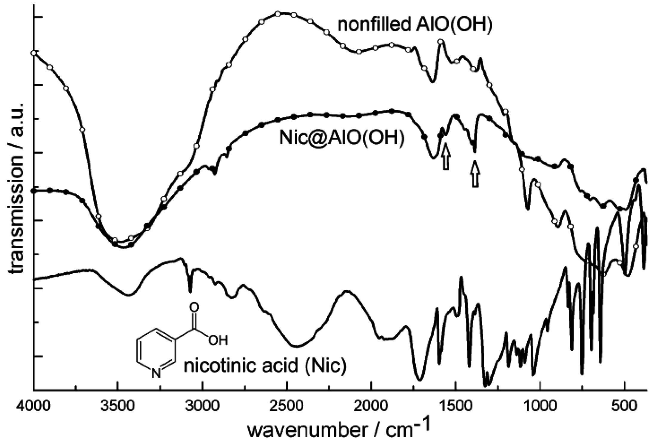
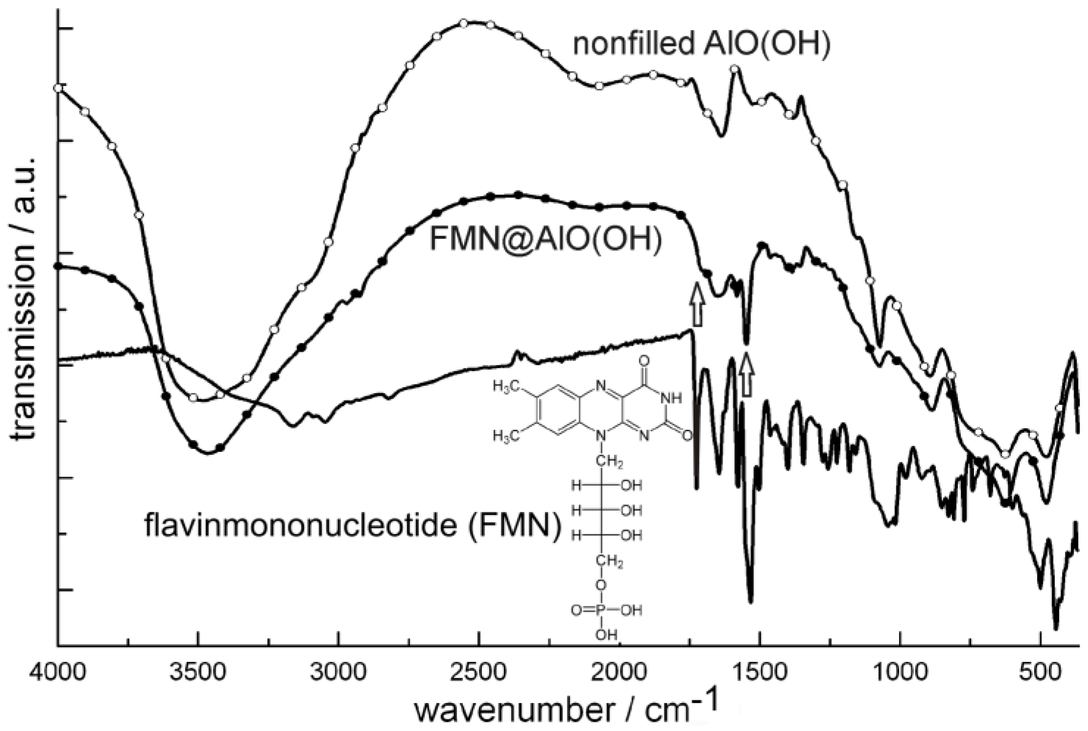
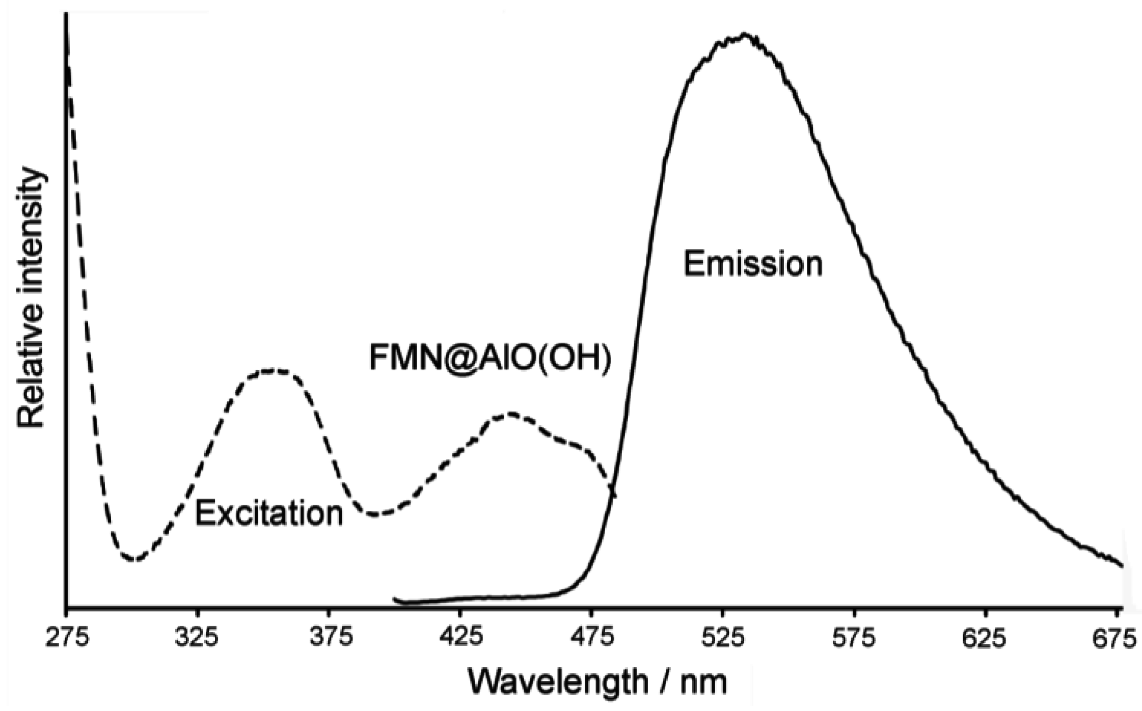
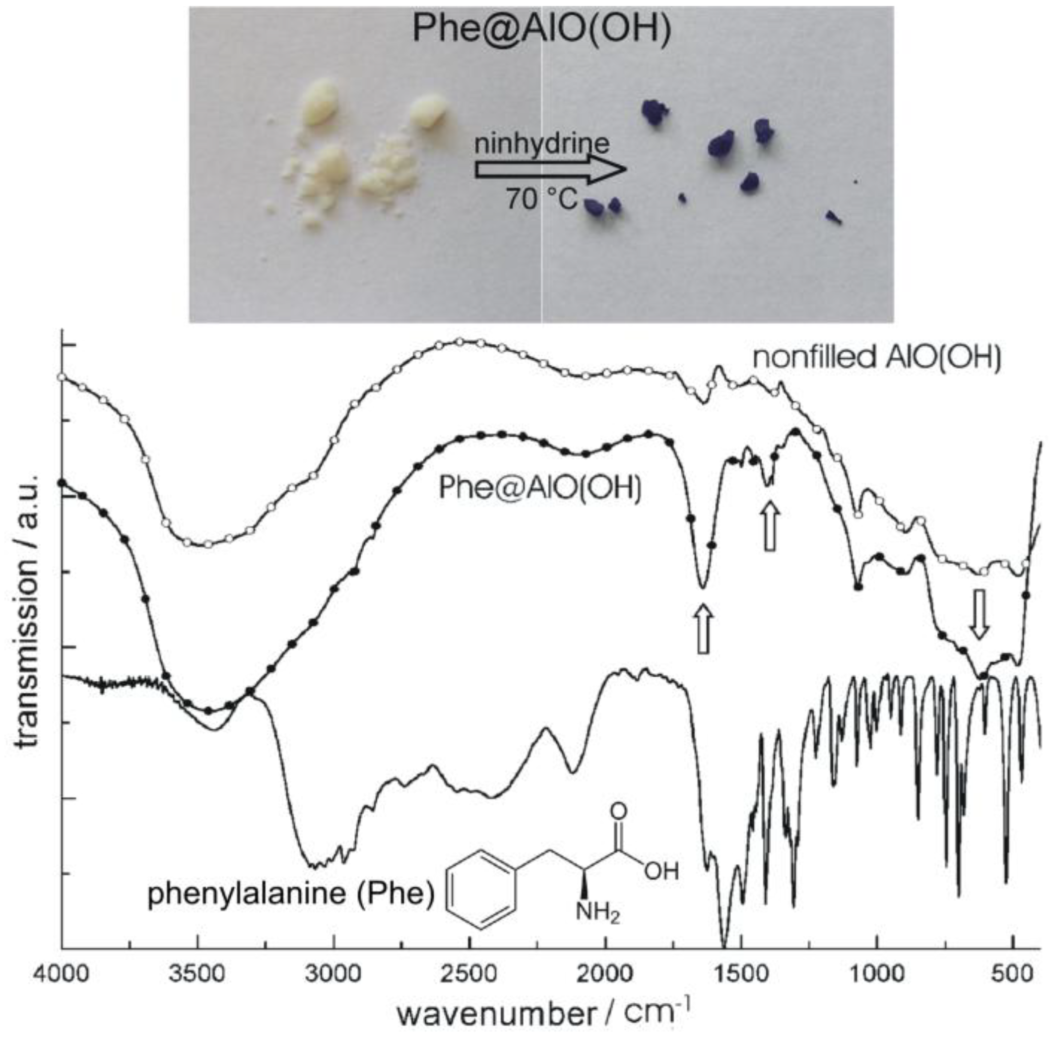
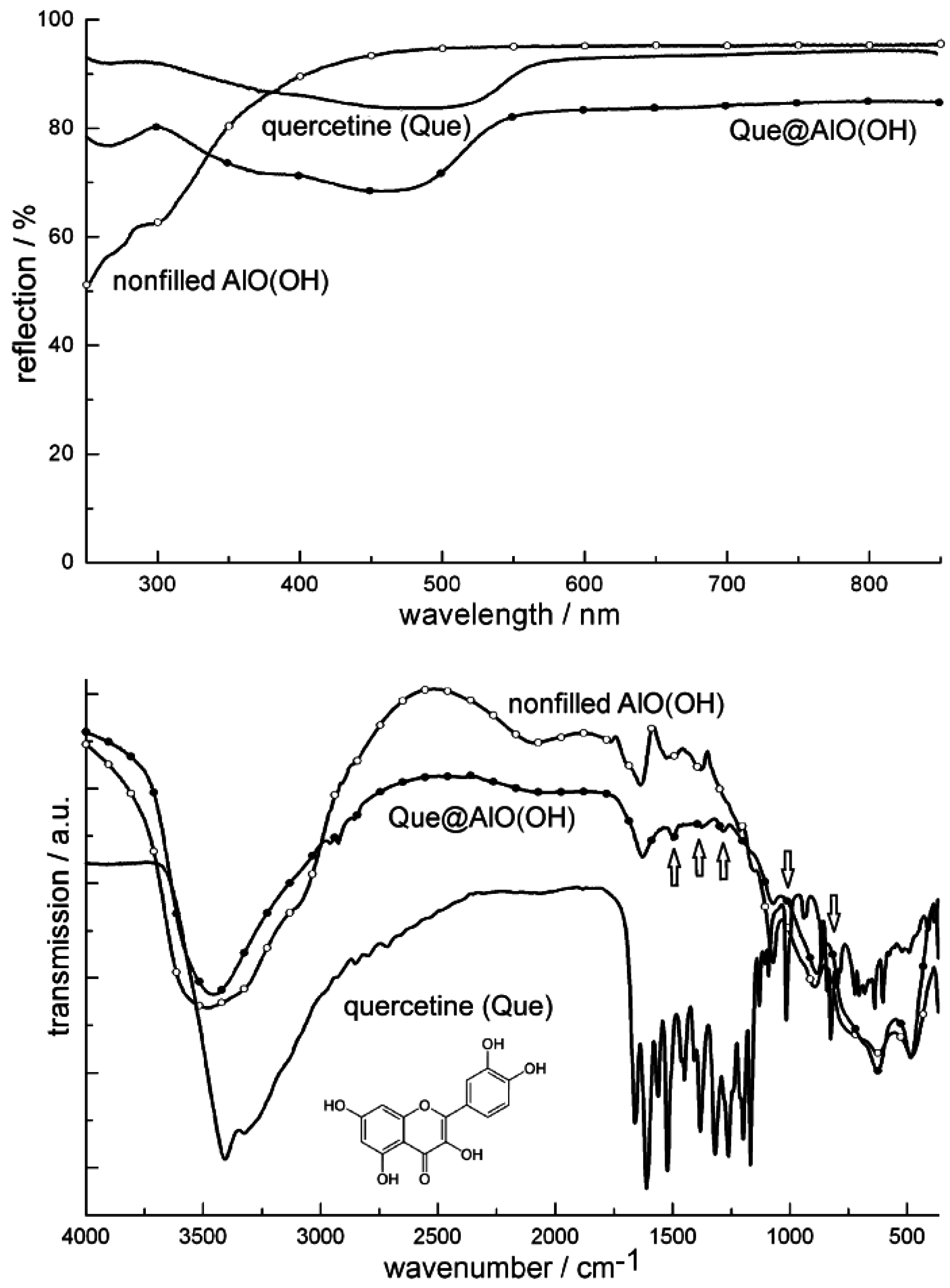
4.2. Encapsulation of biomolecules and bioactive molecules

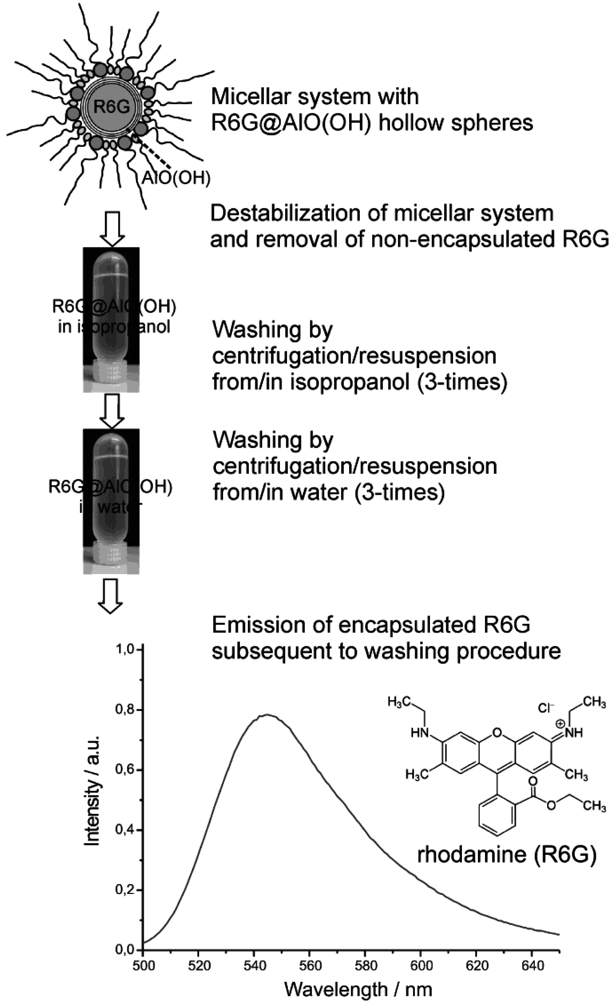
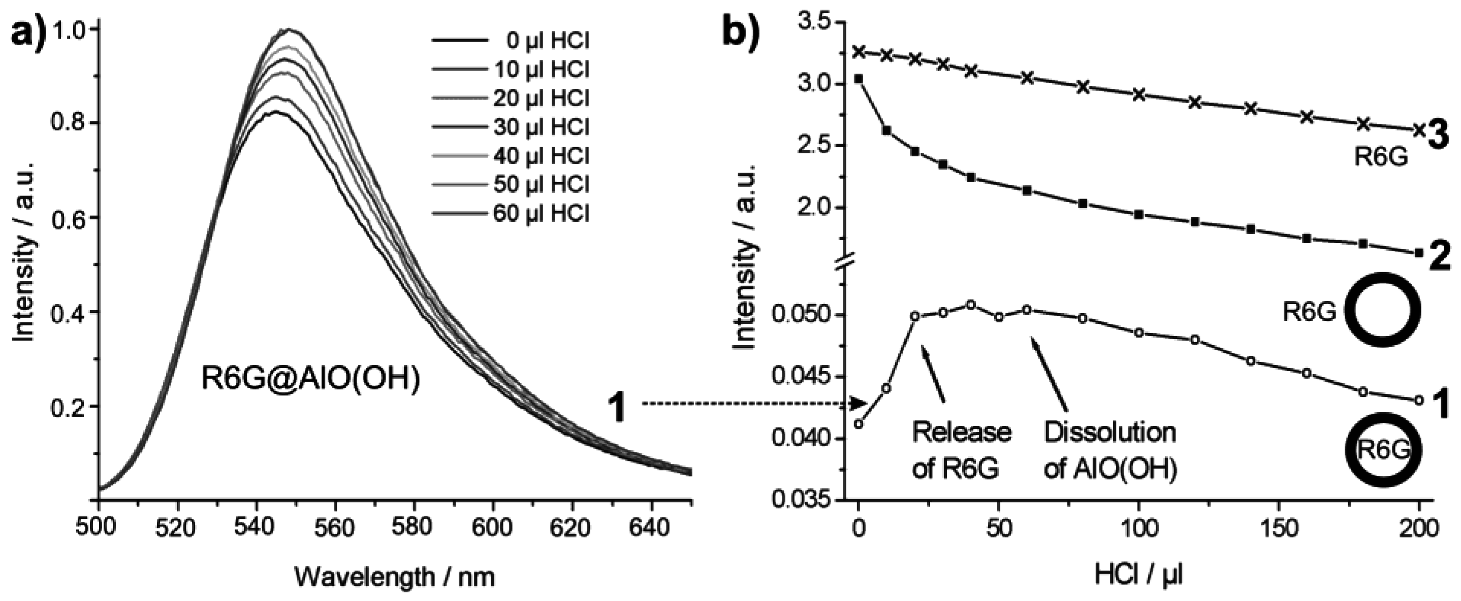
4.3. Encapsulation of fluorescent dyes


5. Perspectives of Nanoscale Hollow Spheres
Acknowledgements
References and Notes
- Schmid, G. Nanoparticles; Wiley-VCH: Weinheim, Germany, 2004. [Google Scholar]
- Ozin, G.A.; Arsenault, A.C. Nanochemistry; RSC Publishing: Cambridge, UK, 2005. [Google Scholar]
- Roduner, E. Nanoscopic Materials: Size-Dependent Phenomena; RCS Publishing: Cambridge, UK, 2006. [Google Scholar]
- Goesmann, H.; Feldmann, C. Nanoparticulate Functional Materials. Angew. Chem. Int. Ed. 2010, 49, 1363–1395. [Google Scholar]
- Hersam, M.C. Progess towards monodisperse single-walled carbone nanotubes. Nature Nanotechnol. 2008, 3, 387–394. [Google Scholar] [CrossRef]
- Sgobba, V.; Gued, D.M. Carbonnanotubes—electronic/electrochemical properties and application for nanoelectronics and photonics. Chem. Soc. Rev. 2009, 38, 165–184. [Google Scholar] [CrossRef] [PubMed]
- Zhou, W.; Bai, X.; Wang, E.; Xie, S. Synthesis, Structure, and Properties of Single-Walled Carbon Nanotubes. Adv. Mater. 2009, 21, 4565–4583. [Google Scholar] [CrossRef]
- Lou, X.W.; Archer, Z.; Yang, Z. Hollow Micro-/Nanostructures: Synthesis and Applications. Adv. Mater. 2008, 20, 3987–4019. [Google Scholar] [CrossRef]
- Kasavajjula, U.; Wang, C.S.; Appleby, A.J. Nano- and bulk-silicon-based insertion anodes for lithium-ion secondary cells. J. Power Sources 2007, 163, 1003–1039. [Google Scholar] [CrossRef]
- Lou, X.W.; Chang, M.L.; Archer, L.A. Designed Synthesis of Coaxial SnO2@carbon Hollow Nanospheres for Highly Reversible Lithium Storage. Adv. Mater. 2009, 21, 2536–2539. [Google Scholar] [CrossRef]
- Li, H. X.; Bian, Z.F.; Zhu, J.; Zhang, D.Q.; Li, G.S.; Huo, Y.N.; Li, H.; Lu, J.F. Mesoporous Titania Spheres with Tunable Chamber Stucture and Enhanced Photocatalytic Activity. J. Am. Chem. Soc. 2007, 129, 8406–8407. [Google Scholar] [CrossRef] [PubMed]
- Liu, Z.Y.; Sun, D.D.; Guo, P.; Leckie, J.O. One-Step Fabrication and High Photocatalytic Activity of Porous TiO2 Hollow Aggregates by Using a Low-Temperature Hydrothermal Method Without Templates. Chem. Europ. J. 2007, 13, 1851–1855. [Google Scholar] [CrossRef]
- Cheon, Y.E.; Suh, M.P. Enhanced Hydrogen Storage by Palladium Nanoparticles Fabricated in a Redox-Active Metal-Organic Framework. Angew. Chem. Int. Ed. 2009, 48, 2899–2903. [Google Scholar] [CrossRef]
- Cobley, C.M.; Campbell, D.J.; Xia, Y. Tailoring the Optical and Catalytic Properties of Gold-Silver Nanoboxes and Nanocages by Introducing Palladium. Adv. Mater. 2008, 20, 748–754. [Google Scholar] [CrossRef] [PubMed]
- Kobayashi, H.; Yamauchi, M.; Kitagawa, H.; Kubota, Y.; Kato, K.; Takata, M. On the Nature of Strong Hydrogen Atom Trapping Inside Pd Nanoparticles. J. Am. Chem. Soc. 2008, 130, 1828–1829. [Google Scholar] [CrossRef] [PubMed]
- Shan, Z.W.; Adesso, G.; Cabot, A.; Sherburne, M.P.; Syed Asif, S.A.; Warren, O.L.; Chrzan, D.C.; Minor, A.M.; Alivisatos, A.P. Ultrahigh stress and strain hierachically structured hollow nanoparticles. Nature Mater. 2008, 7, 947–952. [Google Scholar] [CrossRef]
- Taylor, K.M.L.; Kim, J.S.; Rieter, W.J.; An, H.; Lin, W.; Lin, W. Mesoporous Silica Nanospheres as Highly Efficient MRI Contrast Agents. J. Am. Chem. Soc. 2008, 130, 2154–2155. [Google Scholar] [CrossRef] [PubMed]
- Skrabalak, S.E.; Chen, J.; Au, L.; Lu, X.; Li, X.; Xia, Y. Gold Nanocubes for Biomedical Applicatins. Adv. Mater. 2007, 19, 3177–3184. [Google Scholar] [CrossRef] [PubMed]
- Peyratout, C.S.; Dähne, L. Tailor-Made Polyelectrolyte Microcapsules: From Multilayers to Smart Containers. Angew. Chem. Int. Ed. 2004, 43, 3762–3783. [Google Scholar] [CrossRef]
- Xue, C.; Millstone, J.E.; Li, S.; Mirkin, C.A. Plasmon-Driven Synthesis of Triangular Core-Shell Nanoprisms from Gold Seeds. Angew. Chem. Int. Ed. 2007, 46, 8436–8439. [Google Scholar] [CrossRef]
- Peng, S.; Sun, S. Synthesis and Characterization of Monodisperse Hollow Fe3O4 Nanoparticles. Angew. Chem. Int. Ed. 2007, 46, 4155–4158. [Google Scholar] [CrossRef]
- Xiong, Y.; Wiley, B.; Chen, J.; Li, Z.Y.; Yin, Y.; Xia, Y. Corrosion-Based Synthesis of Single-Crystal Pd Nanoboxes and Nanocages and Their Surface Plasmon Properties. Angew. Chem. Int. Ed. 2005, 44, 7913–7917. [Google Scholar] [CrossRef]
- Sun, Y.; Xia, Y.J. Mechanistic Study on the Replacement Reaction between Silver Nanostructures and Chloroauric Acid in Aqueous Medium. J. Am. Chem. Soc. 2004, 126, 3892–3901. [Google Scholar] [CrossRef] [PubMed]
- Gröger, H.; Gyger, F.; Leidinger, P.; Zurmühl, C.; Feldmann, C. Microemulsion Approach to Nanocontainers and Its Variability in Composition and Filling. Adv. Mater. 2009, 21, 1586–1590. [Google Scholar] [CrossRef]
- Liu, S.; Li, Y.; Xie, M.; Guo, X.; Ji, W.; Ding, W. One-pot synthesis of intestine-like SnO2/TiO2 hollow nanostructures. Mater. Lett. 2010, 64, 402–404. [Google Scholar] [CrossRef]
- Zhu, H.; Wang, J.; Wu, D. Fast Synthesis, Formation Mechanism, and Control of Shell Thickness of CuS Hollow Spheres. Inorg. Chem. 2009, 48, 7099–7104. [Google Scholar] [CrossRef] [PubMed]
- Hang, H.; Zhou, D.; Zhang, L.; Zhang, D.F.; Guo, L.; He, L.; Chen, C.P. Cu2O Hollow Spheres: Synthesis, Characterization and Magnetic Property. J. Nanosci. Nanotechnol. 2009, 9, 1321–1325. [Google Scholar] [CrossRef] [PubMed]
- Wang, D.P.; Zeng, H.C. Multifunctional Roles of TiO2 Nanoparticles for Architecture of Complex Core−Shells and Hollow Spheres of SiO2−TiO2−Polyaniline System. Chem. Mater. 2009, 21, 4811–4823. [Google Scholar] [CrossRef]
- Guo, Z.; Liu, J.; Jia, Y.; Chen, X.; Meng, F.; Li, M.; Liu, J. Template synthesis, organic gas-sensing and optical properties of hollow and porous In2O3 nanospheres. Nanotechnol. 2008, 19, 345704:1–345704:9. [Google Scholar]
- Ras, R.H.A.; Kemell, M.; de Witt, J.; Ritala, M.; ten Brinke, G.; Leskelä, M.; Ikkala, O. Hollow Inorganic Nanospheres and Nanotubes with Tunable Wall Thicknesses by Atomic Layer Deposition on Self-Assembled Polymeric Templates. Adv. Mater. 2007, 19, 102–106. [Google Scholar] [CrossRef]
- Yin, Y.; Erdonmez, C.K.; Cabot, A.; Hughes, S.; Alivisatos, A.P. Colloidal Synthesis of Hollow Cobalt Sulfide Nanocrystals. Adv. Funct. Mater. 2006, 16, 1389–1399. [Google Scholar] [CrossRef]
- Selvakannnan, P.; Sastry, M. Hollow gold and platinum nanoparticles by a transmetallation reaction in an organic solution. Chem. Commun. 2005, 1684–1686. [Google Scholar] [CrossRef]
- Liu, R.; Dong, P.; Chen, S.L. Monodisperse SiO2/TiO2 Core-shell Colloidal Spheres: Synthesis and Ordered Self-assembling. Chem. Lett. 2005, 34, 548–549. [Google Scholar] [CrossRef]
- Wang, Y.; Cai, L.; Xia, Y. Monodisperse spherical colloids of Pb and their use as chemical templates to produce hollow particles. Adv. Mater. 2005, 17, 473–477. [Google Scholar] [CrossRef]
- Dwars, T.; Paetzold, E.; Oehme, G. Reactions in Micellar Systems. Angew. Chem. Int. Ed. 2005, 44, 7174–7199. [Google Scholar] [CrossRef]
- Gradzielski, M. Recent developments in the characterisation of microemulsions. Curr. Opin. Colloid Interface Sci. 2008, 13, 263–269. [Google Scholar] [CrossRef]
- Moulik, S.P.; Rakshit, A.K.; Capek, I. Microemulsions as templates for nanomaterials. Microemulsion 2009, 180–210. [Google Scholar]
- Dörfler, H.D. Grenzflächen und Kolloid-Disperse Systeme; Springer: Berlin, Germany, 2002. [Google Scholar]
- Zhang, D.E.; Tong, Z.W.; Li, S.Z.; Zhang, X. B.; Ying, A. Fabrication and characterization of hollow Fe3O4 nanospheres in a microemulsion. Mater. Lett. 2008, 62, 4053–4055. [Google Scholar] [CrossRef]
- Yu, X.; Cao, C.; Zhu, H.; Li, Q.; Liu, C.; Gong, Q. Nanometer-Sized Copper Sulfide Hollow Spheres with Strong Optical-Limiting Properties. Adv. Funct. Mater. 2007, 17, 1397–1401. [Google Scholar] [CrossRef]
- Garcia-Martinez, J. Nanostructured porous materials - Building matter from the bottom up. Tumor. Chem. Today 2008, 47–71. [Google Scholar]
- Yu, X.; Cao, C.; Zhu, H.; Li, Q.; Liu, C.; Gong, Q. Nanometer-Sized Copper Sulfide Hollow Spheres with Strong Optical-Limiting Properties. Adv. Funct. Mater. 2007, 17, 1397–1401. [Google Scholar] [CrossRef]
- Chen, T.; Colver, P.J.; Bon, S.A.F. Organic-Inorganic Hybrid Hollow Spheres Prepared from TiO2-Stabilized Pickering Emulsion Polymerization. Adv. Mater. 2007, 19, 2286–2289. [Google Scholar] [CrossRef]
- Lu, J.; Chen, D.; Jian, X. Fabrication, characterization, and formation mechanism of hollow spindle-like hematite via a solvothermal process. J. Colloid Interface Sci. 2006, 303, 437–443. [Google Scholar] [CrossRef] [PubMed]
- Jovanovic, D.J.; Validzic, I.L.; Jankovic, I.A.; Bibic, N.; Nedeljkovic, J.M. Synthesis and characterization of shaped ZnS nanocrystals in water in oil microemulsions. Mater. Lett. 2007, 61, 4396–4399. [Google Scholar] [CrossRef]
- Baier, J.; Koetz, K.; Kosmella, S.; Tiersch, B.; Rehage, H. Polyelectrolyte-Modified Inverse Microemulsions and Their Use as Templates for the Formation of Magnetite Nanoparticles. J. Phys. Chem. B 2007, 111, 8612–8618. [Google Scholar] [CrossRef] [PubMed]
- Jiang, X.; Ma, J.; Lin, B.; Ren, Y.; Liu, J.; Zhu, X.; Tao, J.; Wang, X.; Xie, L. Hydrothermal Synthesis of CdMoO4 Nanoparticles. J. Am. Ceram. Soc. 2007, 90, 977–979. [Google Scholar] [CrossRef]
- Althues, H.; Simon, P.; Kaskel, S. Transparent and luminescent YVO4 : Eu/polymer nanocomposites prepared by in situ polymerization. J. Mater. Chem. 2007, 17, 758–765. [Google Scholar] [CrossRef]
- Xiong, L.; He, T. Synthesis and Characterization of Ultrafine Tungsten and Tungsten Oxide Nanoparticles by a Reverse Microemulsion-Mediated Method. Chem. Mater. 2006, 18, 2211–2217. [Google Scholar] [CrossRef]
- Tilley, R.D.; Yamamoto, K. The Microemulsion Synthesis of Hydrophobic and Hydrophilic Silicon Nanocrystals. Adv. Mater. 2006, 18, 2053–2056. [Google Scholar] [CrossRef]
- Buchold, D.H.M.; Feldmann, C. Microemulsion Approach to Non-Agglomerated and Crystalline Nanomaterials. Adv. Funct. Mater. 2008, 18, 1002–1011. [Google Scholar] [CrossRef]
- Feldmann, C.; Jungk, H.O. Polyol-Mediated Preparation of Nanoscale Oxide Particles. Angew. Chem. Int. Ed. 2001, 40, 359–362. [Google Scholar] [CrossRef]
- Feldmann, C. Polyol-Mediated Synthesis of Nanoscale Functional Materials. Adv. Funct. Mater. 2003, 13, 101–107. [Google Scholar] [CrossRef]
- Zimmermann, C.; Feldmann, C.; Wanner, M.; Gerthsen, D. Nanoscale Gold Hollow Spheres Through a Microemulsion Approach. Small 2007, 3, 1347–1349. [Google Scholar] [CrossRef] [PubMed]
- Buchold, D.H.M.; Feldmann, C. Nanoscale γ-AlO(OH) Hollow Spheres: Synthesis and Container-Type Functionality. Nano Lett. 2007, 7, 3489–4392. [Google Scholar] [CrossRef] [PubMed]
- Leidinger, P.; Popescu, R.; Gerthsen, D.; Feldmann, C. Nanoscale La(OH)3 Hollow Spheres and Fine-tuning of Its Outer Diameter and Cavity Size. Small 2010. [Google Scholar] [CrossRef]
- Wedler, G. Lehrbuch der Physikalischen Chemie; Wiley-VCH: Weinheim, Germany, 2004. [Google Scholar]
- Tanaka, N. Spherical aberration-corrected transmission electron microscopy for nanomaterials. Adv. Imaging Electron Phys. 2008, 153, 385–437. [Google Scholar]
- West, A.R. Solid State Chemistry and its Applications; Wiley: Chichester, UK, 1990. [Google Scholar]
- ICDD data base. The International Center for Diffraction Data: Newtown Square, PA, USA, 2010.
- Kind, C.; Popescu, R.; Müller, E.; Gerthsen, D.; Feldmann, C. Microemulsion-based Synthesis of nanoscaled Silver Hollow Spheres and Direct Comparison to Massive Particles of Similar Size. Nanoscale 2010. [Google Scholar] [CrossRef]
- Banhart, F.; Ajayan, P.M. Carbon onions as nanoscopic pressure cells for diamond formation. Nature 1996, 382, 433–435. [Google Scholar]
- Huang, J.Y. In situ Observation of Quasimelting of Diamond and Reversible Graphite−Diamond Phase Transformations. Nano Lett. 2007, 7, 2335–2340. [Google Scholar] [CrossRef] [PubMed]
- Langford, J.I.; Delhez, R.; de Keijser, T.H.; Mittemeijer, E.J. Profile Analysis for crystalline properties by the Fourier and other methods. Aust. J. Phys. 1988, 41, 173–187. [Google Scholar] [CrossRef]
- Gyger, F.; Hübner, M.; Feldmann, C.; Barsan, N.; Weimar, U. Nanoscale SnO2 Hollow Spheres and Its Application as a Gas Sensing Material. Chem. Mater. 2010. [Google Scholar] [CrossRef]
- Colliex, C. Elektronenmikroskopie; Wissenschaftliche Verlagsgemeinschaft: Stuttgart, Germany, 2008. [Google Scholar]
- Williams, P. Motion of small gold clusters in the electron microscope. Appl. Phys. Lett. 1987, 50, 1760–1762. [Google Scholar] [CrossRef]
- Smith, D.J.; Petford-Long, A.K.; Wallenberg, L.R.; Bovin, J.B. Dynamic atomic-level rearrangements in small gold particles. Science 1986, 233, 872–875. [Google Scholar] [CrossRef] [PubMed]
- Ajayan, P.M.; Marks, L.D. Experimental evidence for quasimelting in small particles. Phys. Rev. Lett. 1989, 63, 279–282. [Google Scholar] [CrossRef] [PubMed]
- Ostwald, W. On the supposed isomerism of red and yellow mercury oxide and the surface tension of solid substances. Z. Phys. Chem. 1900, 34, 495–503. [Google Scholar]
- Leidinger, P.; Popescu, R.; Gerthsen, D.; Eul, M.; Pöttgen, R.; Feldmann, C. unpublished results.
- Johnston, A.P.R.; Cortez, C.; Angelatos, A.S.; Caruso, F. Layer-by-layer engineered capsules and their applications. Curr. Opin. Colloid, Interface Sci. 2006, 11, 203–209. [Google Scholar] [CrossRef]
- Peyratout, C.S.; Dähne, L. Tailor-Made Polyelectrolyte Microcapsules: From Multilayers to Smart Containers. Angew. Chem. Int. Ed. 2004, 43, 3762–3783. [Google Scholar] [CrossRef]
- Sukhorukov, G.B.; Frey, A.; Brumen, M.; Möhwald, H. Physical chemistry of encapsulation and release. Phys. Chem. Chem. Phys. 2004, 6, 4078–4089. [Google Scholar] [CrossRef]
- Vougioukalakis, G.C.; Roubelakis, M.M.; Orfanopoulos, M. Open-cage fullerenes: towards the construction of nanosized molecular containers. Chem. Soc. Rev. 2010, 39, 817–844. [Google Scholar] [CrossRef] [PubMed]
- Jander, G.; Blasius, E. Lehrbuch der Analytischen und Präparativen Anorganischen Chemie; Hirzel: Stuttgart, Germany, 2002; p. 418. [Google Scholar]
- Beyer, H.; Walter, W. Lehrbuch der Organischen Chemie; Hirzel: Stuttgart, Germany, 2004; p. 667. [Google Scholar]
- Hunger, K. Industrial Dyes; Wiley-VCH: Weinheim, Germany, 2002. [Google Scholar]
- Du, H.; Fuh, R.A.; Li, J.; Corkan, A.; Lindsey, J.S. PhotoChemCAD: a computer-aided design and research tool in photochemistry. Photochem. Photobiol. 1998, 68, 141–142. [Google Scholar]
© 2010 by the authors; licensee MDPI, Basel, Switzerland. This article is an Open Access article distributed under the terms and conditions of the Creative Commons Attribution license (http://creativecommons.org/licenses/by/3.0/).
Share and Cite
Gröger, H.; Kind, C.; Leidinger, P.; Roming, M.; Feldmann, C. Nanoscale Hollow Spheres: Microemulsion-Based Synthesis, Structural Characterization and Container-Type Functionality. Materials 2010, 3, 4355-4386. https://doi.org/10.3390/ma3084355
Gröger H, Kind C, Leidinger P, Roming M, Feldmann C. Nanoscale Hollow Spheres: Microemulsion-Based Synthesis, Structural Characterization and Container-Type Functionality. Materials. 2010; 3(8):4355-4386. https://doi.org/10.3390/ma3084355
Chicago/Turabian StyleGröger, Henriette, Christian Kind, Peter Leidinger, Marcus Roming, and Claus Feldmann. 2010. "Nanoscale Hollow Spheres: Microemulsion-Based Synthesis, Structural Characterization and Container-Type Functionality" Materials 3, no. 8: 4355-4386. https://doi.org/10.3390/ma3084355
APA StyleGröger, H., Kind, C., Leidinger, P., Roming, M., & Feldmann, C. (2010). Nanoscale Hollow Spheres: Microemulsion-Based Synthesis, Structural Characterization and Container-Type Functionality. Materials, 3(8), 4355-4386. https://doi.org/10.3390/ma3084355