Fabrication and Properties of Carbon Fibers

Abstract
:1. Introduction

| 1999 (tons) | 2004 (tons) | 2006 (tons) | 2008 (tons) | 2010 (tons) | |
|---|---|---|---|---|---|
| Aerospace | 4,000 | 5,600 | 6,500 | 7,500 | 9,800 |
| Industrial | 8,100 | 11,400 | 12,800 | 15,600 | 17,500 |
| Sporting Goods | 4,500 | 4,900 | 5,900 | 6,700 | 6,900 |
| Total | 16,600 | 21,900 | 25,200 | 29,800 | 34,200 |
| PAN (tons) | Pitch (tons) | |
|---|---|---|
| Toray Industries (small tow) | 9,100 | |
| Toho Tenax (Teijin) (small/large tow) | 8,200 | |
| Mitsubishi Rayon/Grafil (small tow) | 4,700 | |
| Zoltek (large tow) | 3,500 | |
| Hexcel (small tow) | 2,300 | |
| Formosa Plastics (small tow) | 1,750 | |
| Cytec Engineered Materials (small tow) | 1,500 | 360 |
| SGL Carbon Group/SGL Technologies (large tow) | 1,500 | |
| Mitsubishi Chemical | 750 | |
| Nippon Graphite Fiber | 120 |
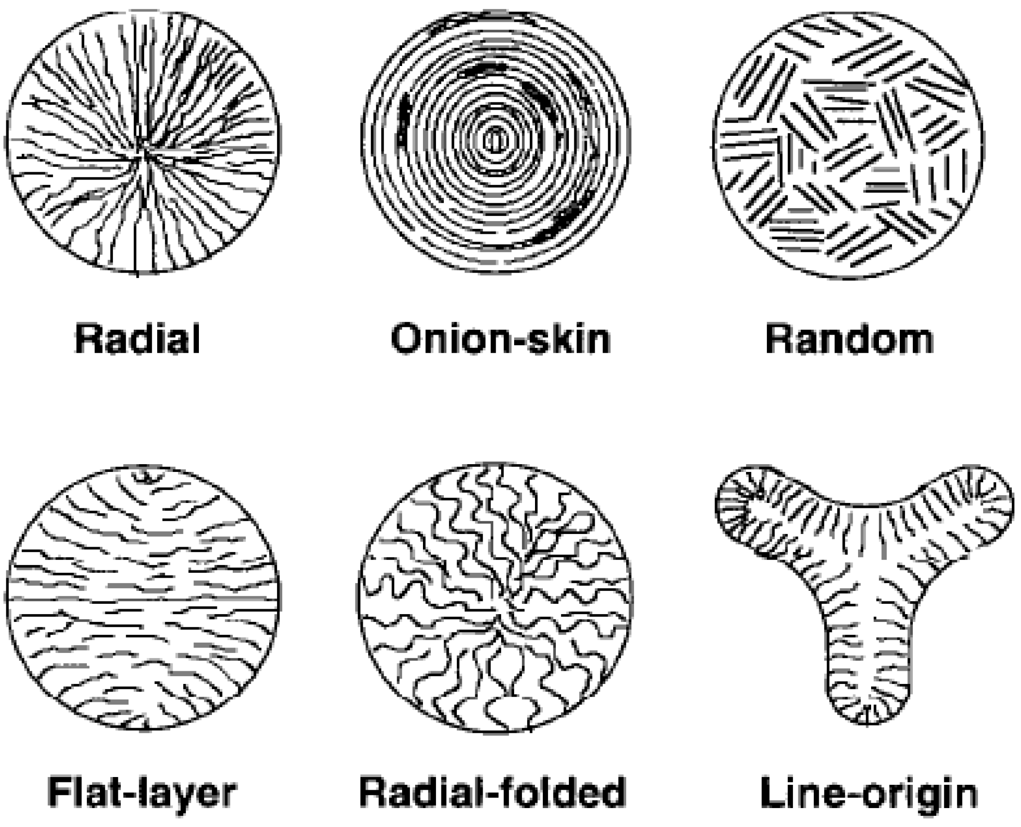
2. Structures and Properties


3. PAN Carbon Fibers
3.1. Precursor Fiber Preparation
3.2. Oxidization/Stabilization

3.3. Carbonization and Graphitization

4. Pitch Carbon Fibers
4.1. Mesophase Preparation and Precursor Fiber Spinning
4.2. Thermal Treatment
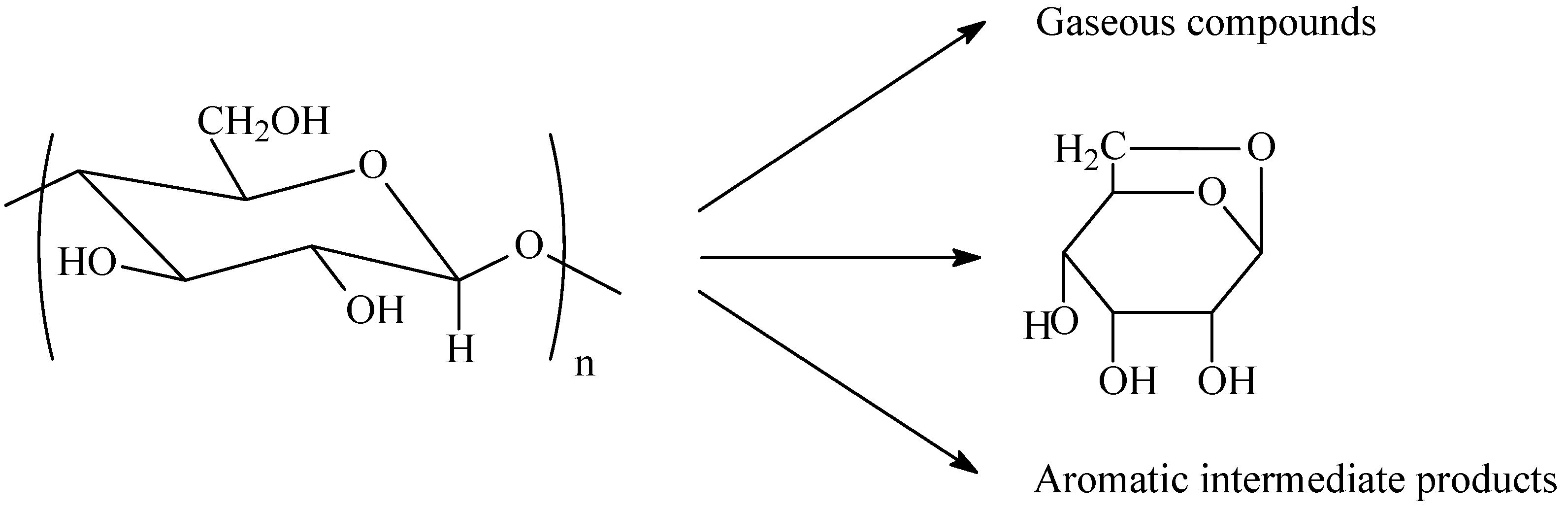
5. Cellulosic Carbon Fibers

6. Carbon Fibers Made from Other Precursors
6.1. Lignin—The Efforts on Cost Reduction
6.2. Other Precursor Materials
7. Future Work
8. Conclusions
Acknowledgements
References and Notes
- Fitzer, E.; Edie, D.D.; Johnson, D.J. Carbon fibers-present state and future expectation; Pitch and mesophase fibers; Structure and properties of carbon fibers. In Carbon Fibers Filaments and Composites, 1st ed.; Figueiredo, J.L., Bernardo, C.A., Baker, R.T.K., Huttinger, K.J., Eds.; Springer: New York, NY, USA, 1989; pp. pp. 3–41, 43–72, 119–146. [Google Scholar]
- Roberts, T. The Carbon Fiber Industry: Global Strategic Market Evaluation 2006–2010; Materials Technology Publications: Watford, UK, 2006; pp. pp. 10, 93–177, 237. [Google Scholar]
- Red, C. Aerospace will continue to lead advanced composites market in 2006. Composites Manuf. 2006, 7, 24–33. [Google Scholar]
- Committee on High Performance Synthetic Fibers for Composites, Commission on Engineering and Technical Systems, National Research Council. High-Performance Synthetic Fibers for Composites; National Academy Press: Washington, DC, USA, 1992; pp. pp. 23, 56–64, 86. [Google Scholar]
- Chung, D.L. Carbon Fiber Composites; Butterworth-Heinemann: Boston, MA, USA, 1994; pp. 3–65. [Google Scholar]
- Donnet, J.B.; Bansal, R.C. Carbon Fibers, 2nd ed.; Marcel Dekker: New York, NY, USA, 1990; pp. 1–145. [Google Scholar]
- Friedlander, H.N.; Peebles, L.H., Jr.; Brandrup, J.; Kirby, J.R. On the chromophore of polyacrylonitrile. VI. Mechanism of color formation in polyacrylonitrile. Macromolecules 1968, 1, 79–86. [Google Scholar] [CrossRef]
- Morley, J.G. High-Performance Fiber Composites; Academic Press: Orlando, FL, USA, 1987; pp. 46–78. [Google Scholar]
- Johnson, W.; Watt, W. Structure of high modulus carbon fibres. Nature 1967, 215, 384–386. [Google Scholar] [CrossRef]
- Wicks, B.J. Microstructural disorder and the mechanical properties of carbon fibers. J. Nucl. Mater. 1975, 56, 287–296. [Google Scholar] [CrossRef]
- Watt, W.; Johnson, W. The effect of length changes during oxidation of polyacrylonitrile fibers on the Young's modulus of carbon fibers. Appl. Polym. Symp. 1969, 9, 215–227. [Google Scholar]
- Fourdeux, A.; Perret, R.; Ruland, W. General structural features of carbon fibers. In Proceedings of the First International Conference on Carbon Fibers, February 1971; Plastics Institute: London, UK; pp. 57–62.
- Perret, R.; Ruland, W. The microstructure of PAN-base carbon fibres. J. Appl. Crystallogr. 1970, 3, 525–532. [Google Scholar] [CrossRef]
- Diefendorf, R.J.; Tokarsky, E. High-performance carbon fibers. Polym. Eng. Sci. 1975, 15, 150–159. [Google Scholar] [CrossRef]
- Edie, D.D. The effect of processing on the structure and properties of carbon fibers. Carbon 1998, 36, 345–362. [Google Scholar] [CrossRef]
- Guigon, M.; Oberlin, A. Preliminary studies of mesophase-pitch-based carbon fibers: Structure and microtexture. Compos. Sci. Technol. 1986, 25, 231–241. [Google Scholar] [CrossRef]
- Fitz Gerald, J.D.; Pennock, G.M.; Taylor, G.H. Domain structure in MP (mesophase pitch)-based fibres. Carbon 1991, 29, 139–164. [Google Scholar] [CrossRef]
- Huang, Y.; Young, R. J. Effect of fiber microstructure upon the modulus of PAN- and pitch-based carbon fibers. Carbon 1995, 33, 97–107. [Google Scholar] [CrossRef]
- Kobets, L.P.; Deev, I.S. Carbon fibres: Structure and mechanical properties. Compos. Sci. Technol. 1997, 57, 1571–1580. [Google Scholar] [CrossRef]
- Konkin, A.A.; Watt, W. Properties of carbon fibers and fields of their application. Production of cellulose based carbon fibrous materials. Chemistry and physics of the conversion of polyacrylonitrile fibers into high modulus carbon fibers. In Strong Fibers; Watt, W., Perov, B.V., Eds.; Elsevier Science Publishers: Amsterdam, The Netherlands, 1985; pp. pp. 241–273, 275–325, 327–387. [Google Scholar]
- Wolff, E.G. Stiffness-thermal expansion relationships in high modulus carbon fibers. J. Compos. Mater. 1987, 21, 81–97. [Google Scholar] [CrossRef]
- Lafdi, K.; Wright, M.A. Carbon fibers. In Handbook of Composites, 2nd ed.; Peters, S.T., Ed.; Chapman & Hall: London, UK, 1998; p. 169. [Google Scholar]
- Reynolds, W.N.; Sharp, J.V. Crystal shear limit to carbon fiber strength. Carbon 1974, 12, 103–110. [Google Scholar] [CrossRef]
- Johnson, J.W.; Thorne, D.J. Effect of internal polymer flaws on strength of carbon fibres prepared from an acrylic precursor. Carbon 1969, 7, 659–660. [Google Scholar] [CrossRef]
- Thorne, D.J. Coating of carbon fiber with carbon. DE 2128526, 1972. [Google Scholar]
- Endo, M. Structure of mesophase pitch-based carbon fibres. J. Mater. Sci. 1988, 23, 598–605. [Google Scholar] [CrossRef]
- Dobb, M.G.; Johnson, D.J.; Park, C.R. Compressional behavior of carbon-fibers. J. Mater. Sci. 1990, 25, 829–834. [Google Scholar] [CrossRef]
- Hahn, H.T.; Sohi, M.M. Buckling of a fiber bundle embedded in epoxy. Compos. Sci. Technol. 1986, 27, 25–41. [Google Scholar] [CrossRef]
- Morgon, P. Carbon Fibers and Their Composites; CRC Press: Boca Raton, FL, USA, 2005; pp. 130–162. [Google Scholar]
- Peebles, L.H. Carbon Fibers: Structure and Formation; CRC Press: New York, NY, USA, 1995; pp. 12–168. [Google Scholar]
- Henrici-Olive, G.; Olive, S. The chemistry of carbon fiber formation from polyacrylonitrile. Adv. Polym. Sci. 1983, 51, 1–60. [Google Scholar]
- Masahiro, T.; Takeji, O.; Takashi, F. Preparation of acrylonitrile precursor for carbon fiber. JP 59204914, 1984. [Google Scholar]
- Knudsen, J.P. The influence of coagulation variables on the structure and physical properties of an acrylic fiber. Text. Res. J. 1963, 33, 13–20. [Google Scholar]
- Daumit, G.P.; Ko, Y.S.; Slater, C.R.; Venner, J.G.; Young, C.C. Formation of melt-spun acrylic fibers possessing a highly uniform internal structure which are particularly suited for thermal conversion to quality carbon fibers. US patent 4935180, 1990. [Google Scholar]
- Daumit, G.P.; Ko, Y.S.; Slater, C.R.; Venner, J.G.; Young, C.C.; Zwick, M.M. Formation of melt-spun acrylic fibers which are well suited for thermal conversion to high strength carbon fibers. US patent 4933128, 1990. [Google Scholar]
- Daumit, G.P.; Ko, Y.S.; Slater, C.R.; Venner, J.G.; Young, C.C. Formation of melt-spun acrylic fibers which are particularly suited for thermal conversion to high strength carbon fibers. US patent 4921656, 1990. [Google Scholar]
- Grove, D.; Desai, P.; Abhiraman, A.S. Exploratory experiments in the conversion of plasticized melt spun PAN-based precursors to carbon fibers. Carbon 1988, 26, 403–411. [Google Scholar] [CrossRef]
- Mukundan, T.; Bhanu, V.A.; Wiles, K.B.; Johnson, H.; Bortner, M.; Baird, D.G.; Naskar, A.K.; Ogale, A.A.; Edie, D.D.; McGrath, J.E. A photocrosslinkable melt processible acrylonitrile terpolymer as carbon fiber precursor. Polymer 2006, 47, 4163–4171. [Google Scholar] [CrossRef]
- Rangarajan, P.; Bhanu, V.A.; Godshall, D.; Wilkes, G.L.; McGrath, J.E.; Baird, D.G. Dynamic oscillatory shear properties of potentially melt processible high acrylonitrile terpolymers. Polymer 2002, 43, 2699–2709. [Google Scholar] [CrossRef]
- Paiva, M.C.; Kotasthane, P.; Edie, D.D.; Ogale, A.A. UV stabilization route for melt-processible PAN-based carbon fibers. Carbon 2003, 41, 1399–1409. [Google Scholar] [CrossRef]
- Imai, K.; Sumoto, M.; Nakamura, H.; Miyahara, N. Process for preparing carbon fibers of high strength. US patent 4902762, 1990. [Google Scholar]
- Ohsaki, T.; Imai, K.; Miyahara, N. Process for preparing a carbon fiber of high strength. US Pat. 4925604, 1990. [Google Scholar]
- Hirotaka, S.; Hiroaki, K. Manufacturing process of isotactic copolymer for carbon fiber precursor. JP2006016482, 2006. [Google Scholar]
- Kuwahara, H.; Suzuki, H.; Matsumura, S. Polymer for carbon fiber precursor. US Pat. 7338997, 2008. [Google Scholar]
- Hunter, W.L. Liability of the α-hydrogen in PAN. J. Polym. Sci. B. 1967, 5, 23–26. [Google Scholar] [CrossRef]
- Warren, C.D.; Paulauskas, F.L.; Baker, F.S.; Eberle, C.C.; Naskar, A. Multi-task research program to develop commodity grade, lower cost carbon fiber. In Proceedings of the SAMPE Fall Technical Conference, Memphis, TN, USA, September 2008.
- Dasarathy, H.; Schimpf, W.C.; Burleson, T.; Smith, S.B.; Herren, C.W.; Frame, A.C.; Heatherly, P.W. Low cost carbon fiber from chemically modified acrylics. In Proceedings of the International SAMPE Technical Conference, Baltimore, MD, USA, May 2002.
- Bajaj, P.; Paliwal, D.K.; Gupta, A.K. Influence of metal ions on structure and properties of acrylic fibers. J. Appl. Polym. Sci. 1998, 67, 1647–1659. [Google Scholar] [CrossRef]
- Shiromoto, K.; Adachi, Y.; Nabae, K. Process for producing carbon fiber. US Pat. 4944932, 1990. [Google Scholar]
- Masaki, T.; Komatsubara, T.; Tanaka, Y.; Nakanishi, S.; Nakagawa, M.; Kanamori, J. Finish for carbon fiber precursors. US Pat. 5783305, 1998. [Google Scholar]
- Houtz, R.C. Orlan acrylic fibre: Chemistry and properties. J. Text. Res. 1950, 20, 786–801. [Google Scholar] [CrossRef]
- Schurz, J. Discoloration effects in acrylonitrile polymers. J. Polym. Sci. 1958, 28, 438–439. [Google Scholar] [CrossRef]
- Standage, A.; Matkowshi, R. Thermal oxidation of polyacrylonitrile. Eur. Polym. J. 1971, 7, 775–783. [Google Scholar] [CrossRef]
- Goodhew, P.J.; Clarke, A.J.; Bailey, J.E. A review of the fabrication and properties of carbon fibres. Mater. Sci. Eng. 1975, 17, 3–30. [Google Scholar] [CrossRef]
- Clarke, A.J.; Bailey, J.E. Oxidation of acrylic fibres for carbon fibre formation. Nature 1973, 243, 146–150. [Google Scholar] [CrossRef]
- Bailey, J.E.; Clarke, A.J. Carbon fibres. Chem. Br. 1970, 6, 484–489. [Google Scholar]
- Goodhew, P.J.; Clarke, A.J.; Bailey, J.E. Review of fabrication and properties of carbon-fibers. Mater. Sci. Eng. 1975, 17, 3–30. [Google Scholar] [CrossRef]
- Henrici-Olive, G.; Olive, S. Molecular interactions and macroscopic properties of polyacrylnitrile and model substances. Adv. Polym. Sci. 1979, 32, 123–152. [Google Scholar]
- Ganster, J.; Fink, H.P.; Zenke, I. Chain conformation of polyacrylonitrile: A comparison of model scattering and radial distribution functions with experimental wide-angle X-ray scattering results. Polymer 1991, 32, 1566–1573. [Google Scholar] [CrossRef]
- Gupta, A.; Harrison, I.R. New aspects in the oxidative stabilization of PAN-based carbon fibers. Carbon 1996, 34, 1427–1445. [Google Scholar] [CrossRef]
- Fitzer, E.; Muller, D.J. The influence of oxygen on the chemical reactions during stabilization of PAN as carbon fiber precursor. Carbon 1975, 13, 63–69. [Google Scholar] [CrossRef]
- Fitzer, E.; Frohs, W.; Heine, M. Optimization of stabilization and carbonization treatment of PAN fibres and structural characterization of the resulting carbon fibres. Carbon 1986, 24, 387–395. [Google Scholar] [CrossRef]
- Yoshinori, N.; Takamaro, K.; Keitarou, F.; Takamaro, K.; Keitaro, F. Process for producing carbon fibers. GB 1500675, 1978. [Google Scholar]
- Hamada, M.; Hosako, Y.; Yamada, T.; Shimizu, T. Acrylonitrile-based precursor fiber for the formation of carbon fiber, process for preparing same, and carbon formed from same. US Pat. 6326451, 2001. [Google Scholar]
- Potter, W.D.; Scott, G. Initiation of low-temperature degradation of polyacrylonitrile. Nat.-Phys. Sci. 1972, 236, 32. [Google Scholar] [CrossRef]
- Raskovic, V.; Marinkovic, S. Temperature dependence of processes during oxidation of PAN fibres. Carbon 1975, 13, 535–538. [Google Scholar] [CrossRef]
- Raskovic, V.; Marinkovic, S. Processes in sulfur dioxide treatment of PAN fibers. Carbon 1978, 16, 351–357. [Google Scholar] [CrossRef]
- Deurberque, A.; Oberlin, A. Stabilization and carbonization of PAN-based carbon fibers as related to mechanical properties. Carbon 1991, 29, 621–628. [Google Scholar] [CrossRef]
- Turner, W.N.; Johnson, F.C. Method of manufacturing carbon articles. US Pat. 3767773, 1973. [Google Scholar]
- Gump, K.H.; Stuetz, D.E. Stabilization of acrylic fibers and films. US Pat. 4004053, 1977. [Google Scholar]
- Kishimoto, S.; Okazaki, S. Process for producing carbon fibers. US Pat. 4009248, 1977. [Google Scholar]
- Kishimoto, S.; Okazaki, S. Process for producing carbon fibers having excellent properties. US Pat. 4024227, 1977. [Google Scholar]
- Riggs, J.P. Thermally stabilized acrylic fibers produced by sulfation and heating in an oxygen-containing atmosphere. US Pat. 3650668, 1972. [Google Scholar]
- Riggs, J.P. Acrylic fiber stabilization catalyzed by Co(II) and Ce(III) cations. US Pat. 3656882, 1972. [Google Scholar]
- Riggs, J.P. Process for the stabilization of acrylic fibers. US Pat. 3656883, 1972. [Google Scholar]
- Ko, T.H.; Yieting, H.; Lin, C.H. Thermal stabilization of polyacrylonitrile fibers. J. Appl. Polym. Sci. 1988, 35, 631–640. [Google Scholar] [CrossRef]
- Shiedlin, A.; Marom, G.; Zillkha, A. Catalytic initiation of polyacrylonitrile stabilization. Polymer 1985, 26, 447–451. [Google Scholar] [CrossRef]
- Mccabe, M.V. Pretreatment of PAN fiber. US Pat. 4661336, 1987. [Google Scholar]
- Mladenov, I.; Lyubekeva, M. Polyacrylonitrile fibers treated by hydrazine hydrate as a basis for the production of carbon fibers. J. Polym. Sci. A1 1983, 21, 1223–1226. [Google Scholar]
- White, S.M.; Spruiell, J.E.; Paulauskas, F.L. Fundamental studies of stabilization of polyacrylonitrile precursor, Part 1: Effects of thermal and environmental treatments. In Proceedings of the International SAMPE Technical Conference, Long Beach, CA, USA, May 2006.
- Allen, S.; Cooper, G.A.; Johnson, D.J.; Mayer, R.M. Carbon fibres of high modulus. In Proceeding of the 3rd Conference on Industrial Carbons and Graphite, Society of Chemical Industry, London, UK, April 1970.
- Paulauskas, F.L.; White, T.L.; Spruiell, J.E. Structure and properties of carbon fibers produced using microwave-assisted plasma technology, Part 2. In Proceedings of the International SAMPE Technical Conference, Long Beach, CA, USA, May 2006.
- Sung, M.G.; Sassa, K.; Tagawa, T.; Miyata, T.; Ogawa, H.; Doyama, M.; Yamada, S.; Asai, S. Application of a high magnetic field in the carbonizatino process to increase the strength of carbon fibers. Carbon 2002, 40, 2013–2020. [Google Scholar] [CrossRef]
- Smith, F.A.; Eckle, T.F.; Osterholm, R.J.; Stichel, R.M. Manufacture of coal tar and pitches. In Bituminous Materials; Hoiberg, A.J., Ed.; InterScience Publishers: New York, NY, USA, 1966; Vol. 3, p. 57. [Google Scholar]
- Barr, J.B.; Chwastiak, S.; Didchenko, R.; Lewis, I.C.; Lewis, R.T.; Singer, L.S. High modulus carbon fibers from pitch precursors. Appl. Polym. Symp. 1976, 29, 161–173. [Google Scholar]
- Otani, S. On the carbon fiber from the molten pyrolysis products. Carbon 1965, 3, 31–38. [Google Scholar] [CrossRef]
- Otani, S.; Yamada, K.; Koitabashi, T.; Yokoyama, A. On the raw materials of MP carbon fiber. Carbon 1966, 4, 425–432. [Google Scholar] [CrossRef]
- Singer, L.S. High modulus, high strength carbon fibers produced from mesophase pitch. US Pat. 4005183, 1977. [Google Scholar]
- Lewis, I.C. Process for producing carbon fibers from mesophase pitch. US Pat. 4032430, 1977. [Google Scholar]
- Chwastiak, S.; Lewis, I.C. Solubility of mesophase pitch. Carbon 1978, 16, 156–157. [Google Scholar] [CrossRef]
- Fu, T.W.; Katz, M. Process for making mesophase pitch. US Pat. 4999099, 1991. [Google Scholar]
- Peter, S.; Beneke, H.; Oeste, F.; Fexer, W.; Jaumann, W.; Meinbreckse, M.; Kempfert, J. A method for the production of a carbon fiber precursor. US Pat. 4756818, 1988. [Google Scholar]
- Bolanos, G.; Liu, G.Z.; Hochgeschurtz, T.; Thies, M.C. Producing a carbon fiber precursor by supercritical fluid extraction. Fluid Phase Equilibria 1993, 82, 303–310. [Google Scholar] [CrossRef]
- Diefendorf, R.J.; Riggs, D.M. Forming optically anisotropic pitches. US Pat. 4208267, 1980. [Google Scholar]
- Angier, D.J.; Barnum, H.W. Neomesophase formation. US Pat. 4184942, 1980. [Google Scholar]
- Yamada, Y.; Honda, H.; Inoue, T. Preparation of carbon fiber. JP 58018421, 1983. [Google Scholar]
- Otani, S. Dormant mesophase pitch. JP 57100186, 1982. [Google Scholar]
- Kalback, W.; Romine, E.; Bourrat, X. Solvated mesophase pitches. US Pat. 5259947, 1993. [Google Scholar]
- Romine, E.; Rodgers, J.; Southard, M.; Nanni, E. Solvating component and solvent system for mesophase pitch. US Pat. 6717021, 2004. [Google Scholar]
- Yamada, Y.; Imamura, T.; Shibata, M.; Arita, S.; Honda, H. Method for the preparation of pitches for spinning carbon fibers. US Pat. 4606808, 1986. [Google Scholar]
- Seo, I.; Sakaguchi, Y.; Kashiwadate, K. Process for producing carbon fibers and the carbon fibers produced by the process. US Pat. 4863708, 1989. [Google Scholar]
- Seo, I.; Oono, T.; Murakami, Y. Catalytic process for producing raw material pitch for carbon materials from naphthalene. US Pat. 5066779, 1991. [Google Scholar]
- Mochida, I.; Shimizu, K.; Korai, Y.; Otsuka, H.; Sakai, Y.; Fujiyama, S. Preparation of mesophase pitch from aromatic-hydrocarbons by the aid of HF/BF3. Carbon 1990, 28, 311–319. [Google Scholar] [CrossRef]
- Korai, Y.; Nakamura, M.; Mochida, I.; Sakai, Y.; Fujiyama, S. Mesophase pitches prepared from methylnaphthalene by the aid of HF/BF3. Carbon 1991, 29, 561–567. [Google Scholar] [CrossRef]
- Watanabe, F.; Ishida, S.; Korai, Y.; Mochida, I.; Kato, I.; Sakai, Y.; Kamatsu, M. Pitch-based carbon fiber of high compressive strength prepared from synthetic isotropic pitch containing mesophase spheres. Carbon 1999, 37, 961–967. [Google Scholar] [CrossRef]
- Kofui, Y.; Ishida, S.; Watanabe, F.; Yoon, S.H.; Wang, Y.G.; Mochida, I.; Kato, I.; Nakamura, T.; Sakai, Y.; Komatsu, M. Preparation of carbon fiber from isotropic pitch containing mesophase spheres. Carbon 1997, 35, 1733–1737. [Google Scholar] [CrossRef]
- Kohn, E.M. Use of hot buoyant liquid to convert pitch to continuous carbon filament. US Pat. 3972968, 1976. [Google Scholar]
- Vakili, A.; Yue, Z.R.; Fei, Y.; Cochran, H.; Allen, L.; Duran, M. Pitch based carbon fiber processing and composites. In Proceedings of the International SAMPE Technical Conference, Cincinnati, OH, USA, October 2007.
- Yue, Z.R.; Matthew, D.P.; Vakili, A. Fabrication of low-cost composites using roving-like mesophase pitch-based carbon fibers. In Proceedings of the 17th International Conference on Composites/Nanocomposites Engineering, Honolulu, HI, USA, July 2009.
- Sawaki, T.; Sasaki, H.; Nakamura, T.; Sadanobu, J. Process for preparation of high-performance grade carbon fibers. US Pat. 4840762, 1989. [Google Scholar]
- Sasaki, H.; Sawaki, T. Method of manufacturing of pitch-base carbon fiber. US Pat. 4948574, 1990. [Google Scholar]
- Miyajima, N.; Akatsu, T.; Ikoma, T.; Ito, O.; Rand, B.; Tanabe, Y.; Yasuda, E. A role of charge-transfer complex with iodine in the modification of coal tar pitch. Carbon 2000, 38, 1831–1838. [Google Scholar] [CrossRef]
- Bright, A.A.; Singer, L.S. Electronic and structural characteristic of carbon-fibers from mesophase pitch. Carbon 1979, 17, 59–69. [Google Scholar] [CrossRef]
- McHenry, E.R. Process for producing mesophase pitch. US Pat. 4026788, 1977. [Google Scholar]
- Guigon, M.; Oberlin, A.; Desarmot, G. Microtexture and structure of some high-modulus PAN-based carbon fibres. Fibre Sci. Technol. 1984, 20, 177–198. [Google Scholar] [CrossRef]
- Guigon, M.; Oberlin, A.; Desarmot, G. Microtexture and structure of some high tensile strength, PAN-base carbon fibers. Fibre Sci. Technol. 1984, 20, 55–72. [Google Scholar] [CrossRef]
- Singer, L.S. The mesophase and high modulus carbon fibers from pitch. Carbon 1978, 16, 409–415. [Google Scholar] [CrossRef]
- Riggs, D.M. Process of spinning pitch-based carbon fibers. US Pat. 4504454, 1985. [Google Scholar]
- Otani, S.; Oya, A. Status report on pitch-based carbon fiber in Japan. In Composites ‘86: Recent Advances in Japan and the United States, Japan Society for Composite Materials; Kawata, K., Umekawa, S., Kobayashi, A., Eds.; Japan Society for Composite Materials: Tokyo, Japan, 1986; pp. 1–10. [Google Scholar]
- Peebles, L.H. Carbon Fibers: Formation, Structure, and Properties, 1st ed.; CRS Press: Boca Raton, FL, USA, 1994; p. 3. [Google Scholar]
- Tang, M.M.; Bacon, R. Carbonization of cellulose fibers-I. Low temperature pyrolysis. Carbon 1964, 2, 211–214. [Google Scholar] [CrossRef]
- Bacon, R. Carbon fibers from rayon precursors. In Chemistry and Physics of Carbon; Walker, P.L., Jr., Thrower, P.A., Eds.; Marcel Dekker: New York, NY, USA, 1974; Vol. 9, p. 1. [Google Scholar]
- Tang, W.K.; Neill, M.K. Effect of flame retardants on pyrolysis and combustion of α-cellulose. J. Polym. Sci. C 1964, 6, 65–81. [Google Scholar] [CrossRef]
- Shindo, A.; Nakanishi, Y.; Sema, I. Carbon fibers from cellulose fibers. Appl. Polym. Symp. 1969, 9, 271–284. [Google Scholar]
- Woerner, H.J.; Lukacs, D.J.; Hoffmann, K. Production of Flexible Carbon Fibres. GB 1194176, 1970. [Google Scholar]
- Otani, S.; Fukuoka, Y.; Igarashi, B.; Sasaki, K. Method for producing carbonized lignin fiber. US Pat. 3461082, 1969. [Google Scholar]
- Sudo, K.; Shimizu, K. A new carbon-fiber from lignin. J. Appl. Polym. Sci. 1992, 44, 127–134. [Google Scholar] [CrossRef]
- Sudo, K.; Shimizu, K.; Nakashima, N.; Yokoyama, A. A new modification method of exploded lignin for the preparation of a carbon fiber precursor. J. Appl. Polym. Sci. 1993, 48, 1485–1491. [Google Scholar] [CrossRef]
- Uraki, Y.; Kubo, S.; Nigo, N.; Sano, Y.; Sasaya, T. Preparation of carbon-fibers from Organosolv lignin obtained by aqueous acetic-acid pulping. Holzforschung 1995, 49, 343–350. [Google Scholar] [CrossRef]
- Kubo, S.; Uraki, Y.; Sano, Y. Preparation of carbon fibers from softwood lignin by atmospheric acetic acid pulping. Carbon 1998, 36, 1119–1124. [Google Scholar] [CrossRef]
- Kadla, J.F.; Kubo, S.; Venditti, R.A.; Gilbert, R.D.; Compere, A.L.; Griffith, W. Lignin-based carbon fibers for composite fiber application. Carbon 2002, 40, 2913–2920. [Google Scholar] [CrossRef]
- Kubo, S.; Kadla, J.F. Lignin-based carbon fibers: Effect of synthetic polymer blending on fiber properties. J. Polym. Environ. 2005, 13, 97–105. [Google Scholar] [CrossRef]
- Braun, J.L.; Holtman, K.M.; Kadla, J.F. Lignin-based carbon fibers: Oxidative thermostabilization of kraft lignin. Carbon 2005, 43, 385–394. [Google Scholar] [CrossRef]
- Gellerstedt, G.; Pettersson, B. Autooxidation of lignin. Svensk Papperstidn. 1980, 83, 314–318. [Google Scholar]
- Fenner, R.A.; Lephardt, J.O. Examination of the thermal-decomposition of kraft pine lignin by Fourier-transform infrared evolved gas-analysis. J. Agric. Food Chem. 1981, 29, 846–849. [Google Scholar] [CrossRef]
- Schmidt, J.A.; Rye, C.S.; Gurnagul, N. Lignin inhibits autoxidative degradation of cellulose. Polym. Degrad. Stab. 1995, 49, 291–297. [Google Scholar] [CrossRef]
- Majibur, M.; Khan, R.; Gotoh, Y.; Morikawa, H.; Miura, M.; Fujimori, Y.; Nagura, M. Carbon fiber from natural biopolymer: Bombyxmori silk fibroin with iodine treatment. Carbon 2007, 45, 1035–1042. [Google Scholar] [CrossRef]
- Bengisu, M.; Yilmaz, E. Oxidation and pyrolysis of chitosan as a route for carbon fiber derivation. Carbohydr. Polym. 2002, 50, 165–175. [Google Scholar] [CrossRef]
- Prauchner, M.J.; Pasa, V.M.D.; Otani, S.; Otani, C. Biopitch-based general purpose carbon fibers: Processing and properties. Carbon 2005, 43, 591–597. [Google Scholar] [CrossRef]
- Sliva, D.E.; Selley, W. Continuous method for making spinnable polyacetylene solutions convertible to high strength carbon fiber. US Pat. 3928516, 1975. [Google Scholar]
- Krutchen, C.M. Melt extrudable polyacetylene copolymer blends. US Pat. 3852235, 1974. [Google Scholar]
- Mavinkurve, A.; Visser, S.; Pennings, A.J. An initial evaluation of poly(vinylacetylene) as a carbon-fiber precursor. Carbon 1995, 33, 757–761. [Google Scholar] [CrossRef]
- Horikiri, S.; Iseki, J.; Minobe, M. Process for production of carbon fiber. US Pat. 4070446, 1978. [Google Scholar]
- Ashitaka, H.; Ishikawa, H.; Ueno, H.; Nagasaka, A. Syndiotactic 1,2-polybutadiene with CO-CS2 catalyst system 1. Preparation, properties, and application of highly crystalline syndiotactic 1,2-polybutadiene. J. Polym. Sci. A1 1983, 21, 1853–1860. [Google Scholar]
- Ashitaka, H.; Kusuki, Y.; Yakamoto, S.; Onata, Y.; Nagasaki, A. Preparation of carbon-fibers from syndiotactic 1,2-polybutadiene. J. Appl. Polym. Sci. 1984, 29, 2763–2776. [Google Scholar] [CrossRef]
- Nagasaka, A.; Ashitaka, H.; Kusuki, Y.; Oda, D.; Yoshinaga, T. Process for producing carbon fiber. US Pat. 4131644, 1978. [Google Scholar]
- Newell, J.A.; Edie, D.D. Factors limiting the tensile strength of PBO-based carbon fibers. Carbon 1996, 34, 551–560. [Google Scholar] [CrossRef]
- Kawamura, K.; Jenkins, G.M. Mechanical properties of glassy carbon fibers derived from phenolic resin. J. Mater. Sci. 1972, 7, 1099–1112. [Google Scholar] [CrossRef]
- Jenkins, G.M.; Kawamura, K. Phenolic resin fibres. GB 1228910 1971. [Google Scholar]
- Yokota, H.; Kobayashi, A.; Horikawa, J.; Miyashita, A. Process for producing carbon products. GB 1406378, 1975. [Google Scholar]
- Santangelo, J.G. Graphitization of fibrous polyamide resinous materials. US Pat. 3547584, 1970. [Google Scholar]
- Economy, J.; Lin, R.Y. Adsorption characteristics of activated carbon fibers. Appl. Polym. Symp. 1976, 29, 199–211. [Google Scholar]
- Jiang, H.; Desai, P.; Kumar, S.; Abhiraman, A.S. Carbon-fibers from poly(para-phenylene benzobisthiazole) (PBZT) fibers-conversion and morphological aspects. Carbon 1991, 29, 635–644. [Google Scholar] [CrossRef]
- Murakami, M. Process for producing graphite. US Pat. 4876077, 1989. [Google Scholar]
- Ezekiel, H.M.; Spain, R.G. Preparation of graphite fibers from polymeric fibers. J. Polym. Sci. C 1967, 19, 249–265. [Google Scholar] [CrossRef]
- Shindo, A.; Fujii, R.; Souma, I. Producing method of carbon or carbonaceous material. US Pat. 3427120, 1969. [Google Scholar]
- Boncher, E.A.; Cooper, R.N.; Everett, D.H. Preparation and structure of Saran-carbon fibers. Carbon 1970, 8, 597–605. [Google Scholar] [CrossRef]
- Soehngen, J.W.; Willians, A.G. Carbon fiber production. US Pat. 4020145, 1977. [Google Scholar]
© 2009 by the authors; licensee Molecular Diversity Preservation International, Basel, Switzerland. This article is an open-access article distributed under the terms and conditions of the Creative Commons Attribution license (http://creativecommons.org/licenses/by/3.0/).
Share and Cite
Huang, X. Fabrication and Properties of Carbon Fibers. Materials 2009, 2, 2369-2403. https://doi.org/10.3390/ma2042369
Huang X. Fabrication and Properties of Carbon Fibers. Materials. 2009; 2(4):2369-2403. https://doi.org/10.3390/ma2042369
Chicago/Turabian StyleHuang, Xiaosong. 2009. "Fabrication and Properties of Carbon Fibers" Materials 2, no. 4: 2369-2403. https://doi.org/10.3390/ma2042369
APA StyleHuang, X. (2009). Fabrication and Properties of Carbon Fibers. Materials, 2(4), 2369-2403. https://doi.org/10.3390/ma2042369