Abstract
Laser shock peening (LSP) significantly enhances fatigue and corrosion resistance, especially in additively manufactured components. This effect is stronger when confinement is used; typically, it is water. However, water poses risks to sensitive electronics. As an alternative, this study explored gel-based confinement. A Ni-based alloy was LSP-treated using 532 nm and 1064 nm wavelengths, with three types of gel compared to water as a control. The results showed that gel confinement can induce compressive residual stresses and increase surface microhardness. However, gels were generally less effective than water in terms of residual stress magnitude and depth of hardening. Additionally, gel confinement required the use of a 1064 nm laser, whereas water confinement was more effective with 532 nm. Among the gels tested, one adhesive variant performed best due to improved surface contact and strong adhesion. The observed increase in microhardness and compressive stress was linked to surface grain refinement and twinning. Overall, adhesive gels offer potential benefits for LSP, particularly for additively manufactured parts, which often have high surface roughness and require non-conductive confinement solutions.
1. Introduction
Laser shock peening (LSP) is an emerging surface treatment technology that induces beneficial compressive residual stresses (CRS) in the treated material. It is similar in effect to the more conventional shot Peening (SP), but LSP offers significantly higher strain rates and deeper penetration of the stress field, resulting in more pronounced industrial benefits [1]. Due to its versatility and effectiveness on metallic materials and alloys, LSP is now widely applied in advanced manufacturing across the aerospace [2], nuclear [3], transportation [4], and biomedical industries [5].
LSP operates by irradiating the material surface with repeated high-energy laser pulses [6]. This leads to rapid vaporization near the surface and intense ionization of atoms, generating a rapidly expanding plasma [7]. The plasma induces a high-pressure shock wave that propagates into the material, causing localized plastic deformation when the Hugoniot elastic limit (HEL) is exceeded [8]. The primary benefit of LSP is the induction of deep, stable compressive residual stresses [9].
The key parameters affecting LSP performance include laser pulse wavelength, duration, shape, and energy density [10,11]. An important enhancement technique is the use of confinement, which significantly increases the shock intensity and effectiveness. Confinement results in more concentrated stress waves, improving fatigue life, corrosion resistance, surface hardness, wear resistance, and even tensile strength of the treated components [12,13,14,15,16,17]. A schematic of the LSP process with confinement is shown in Figure 1.
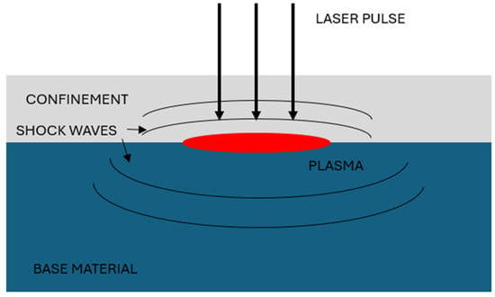
Figure 1.
Schematic of the LSP process on the base material.
Water is the traditional confinement medium in LSP due to its abundance, low cost, and proven effectiveness under certain conditions [18,19]. However, practical challenges and limitations associated with water—such as its incompatibility with sensitive components—have led to the development of alternative confinement methods. One of the most prominent alternatives is solid confinement, typically in the form of glass [20,21] or polymers [22,23].
Solid confinements offer specific advantages over water, particularly in hybrid processes such as laser powder bed fusion (LPBF), where they contribute to improvements in fatigue resistance, dimensional accuracy, and crack healing [24]. They are also useful for treating components used in environments where water contamination must be avoided, such as sensors and electronic parts in aerospace applications, where moisture exposure can be detrimental [25,26,27].
However, solid confinements must be carefully tailored to match complex part geometries. Even surface irregularities, such as high roughness, can hinder their effectiveness [28]. To overcome these issues, gel-like confinements have gained interest as they potentially combine the benefits of both water and solid confinements.
In this study, the effects of three types of gel-like confinements were investigated and compared to water in the LSP treatment of a nickel-based alloy, with the aim of encouraging further research in this promising field.
2. Materials and Methods
The LSP process was conducted on In-718 specimens, with chemical composition tested on a MicroLab 150 (G.N.R., Milan, Italy), presented in Table 1. The material was rolled and stress-relieved at 1065 °C for 90 min by using an MP-3 (Grejac Komerc, Becej, Serbia) laboratory oven with Ar atmosphere. This procedure is in full accordance with the ASTM F3055 standard [29].

Table 1.
Parent metal chemical composition in wt.%, Ni balance.
The LSP process was performed on In-718 plates, with dimensions of 100 × 50 mm and the thickness of 6.86 mm. The LSP process was performed by using a Twins (Quantel, Lannion, France) Nd:YAG 10 ns pulsed laser (Figure 2). Two wavelengths were used: 532 and 1064 nm, with a spot size of Ø1 mm. A ½ overlapping pattern was applied to form the treated area of 12 × 12 mm, which was chosen in accordance with [30]. LSP was performed with 0.47 J energy in seven passes, which was determined as optimal from this group’s previous experiences and publications [31]. Each set of parameters was used to form two treated squares, of which one was used for residual stress measurement, while the other was used for microstructural and microhardness testing.
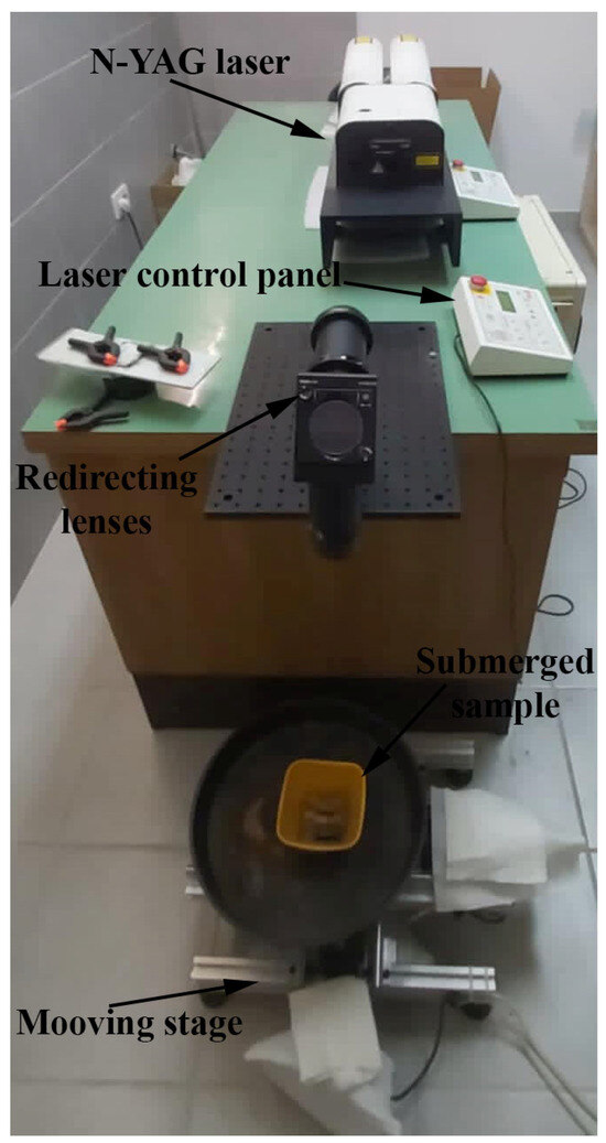
Figure 2.
Experimental setup.
Laser treatment was performed in four confinements, with distilled water as a control specimen, and three gel-like confinements: Sikaflex Crystal Gel (Sika AG, Baar, Switzerland), Neutro Gel (ultrasound gel; Daplex, Belgrade, Serbia), and Vaseline (Medical Pharm, Zemun, Serbia). To improve the readability of the material, a designation system was devised, as shown in Table 2.

Table 2.
Designation system.
Microstructural analysis and microhardness testing were performed on specimens initially cut using an SP43 (Makino, Tokyo, Japan) wire electrical discharge machining (EDM) system, equipped with a 0.25 mm Megacut wire (Bedra, Heuchelheim, Germany). Metallographic preparation was conducted in a Struers laboratory, starting with mounting, followed by grinding with SiC abrasive papers (grit sizes ranging from P500 to P2500) and polishing using diamond suspensions with particle sizes of 6 µm, 3 µm, 1 µm, and ¼ µm. Final surface etching was carried out using aqua regia (a mixture of HNO3 and 3 parts HCl).
Residual stress measurements were conducted using a hole-drilling method, with a Prism (Stresstech, Vaajakoski, Finland) device at multiple positions and a rotation speed of 40,000 rpm, starting at the surface and proceeding in 0.05 mm increments to a maximum depth of 0.8 mm. Each measurement was repeated three times, and the average values were reported.
Microhardness testing was carried out using a Tukon 1102 (Buehler-Wilson, Uzwill, Switzerland) hardness tester, applying a 50 g load. Measurements were taken at 0.05 mm intervals to a depth of 0.8 mm. As with residual stress measurements, three readings were taken and averaged to obtain the final values.
3. Results
3.1. Residual Stresses
The results of the residual stress measurements are presented in Figure 3 and Figure 4. Figure 3 shows the results of LSP treatment using a 532 nm wavelength. These results indicate that water confinement (Figure 3a) induces the highest compressive residual stress at the material surface, exceeding −400 MPa. Compressive stresses extended to a depth of approximately 0.15 mm, beyond which they transitioned into tensile stresses. These tensile values gradually approached the residual stress level of the untreated base material, likely due to the annealing effect from prior thermal processing.
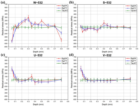
Figure 3.
Residual stresses in the specimens treated with 532 nm: (a) W−532; (b) S−532; (c) U−532; (d) V−532.
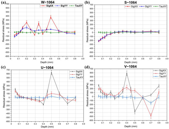
Figure 4.
Residual stresses in the specimens treated with 1064 nm: (a) W-1064; (b) S-1064; (c) U-1064; (d) V-1064.
Alternative confinement methods were less effective in inducing compressive stresses. However, ultrasonic gel and Vaseline confinements produced stable and consistent residual stress profiles, with relatively smooth curves and minimal fluctuations. Notably, shear stresses (τ) were largely unaffected by the LSP process, remaining close to 0 MPa throughout the measured depth.
The residual stress results for the specimens treated with a 1064 nm wavelength are presented in Figure 4. Similar to the results shown in Figure 3 for the 532 nm treatment, ultrasonic gel and Vaseline did not provide sufficient confinement to significantly enhance plasma-induced stress waves. Water confinement was partially effective, inducing compressive stresses of approximately −100 MPa. However, notable fluctuations were observed in the residual stress profile between 0.15 mm and 0.6 mm, including distinct tensile stress peaks at 0.2 mm, 0.35 mm, and 0.5 mm.
The most effective confinement in this case was crystal gel, which generated the highest compressive residual stresses, exceeding −200 MPa. The compressive stress region decreased to 0 MPa at a depth of 0.2 mm, beyond which the residual stress gradually returned to the baseline level of the base material (0 to 40 MPa)—a result of prior annealing.
As with the specimens treated at 532 nm, shear stresses (τ) remained largely unaffected by the LSP process and stayed near neutral values across all the specimens.
3.2. Microhardness Values
The microhardness values of the LSP-treated specimens with different confinements are presented in Figure 5 and Figure 6. Figure 5 shows the microhardness results obtained using a 50 g load (HV0.05) for the specimens treated with a 532 nm laser and various confinement types. It is clear that water confinement (W−532) provides the highest surface microhardness, exceeding 240 HV0.05. At greater depths, the microhardness gradually decreased, stabilizing around 210–220 HV0.05. In contrast, the specimens with other confinements showed either a slight increase in hardness near the surface (S−532) or a decrease in microhardness (U−532 and V−532). In all these cases, the microhardness of the base material remained unchanged, similar to that of the W−532 specimens, indicating that the base material was not significantly affected by the treatment.
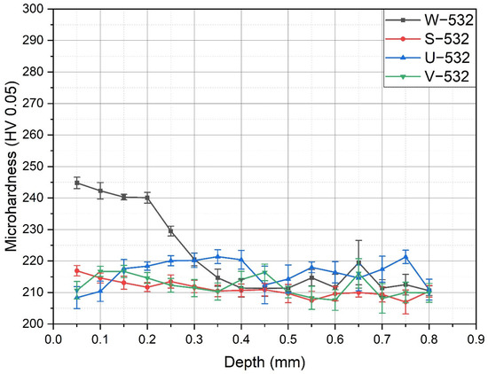
Figure 5.
Microhardness values in the specimens treated with 532 nm.
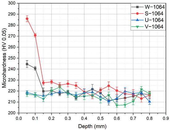
Figure 6.
Microhardness values in the specimens treated with 1064 nm.
The microhardness results for the specimens treated with a 1064 nm wavelength are shown in Figure 6. Similar to the findings with the 532 nm wavelength, the base microhardness of specimens W−1064 and S−1064, as well as U−1064 and V−1064, remained between approximately 210 and 220 HV0.05 across the measured depth range, indicating no significant change beyond the LSP-affected surface.
Specimens W−1064 and S−1064 exhibited a marked increase in microhardness near the surface, where the LSP effect was most pronounced. In specimen W−1064, the maximum microhardness reached the range of 240–250 HV0.05, similar to W−532; however, the depth at which this elevated hardness was measured was 0.1 mm, compared to 0.2 mm in W−532. The highest microhardness was observed in specimen S−1064, where the maximum value approached approximately 300 HV0.05, showing the most significant effect of the LSP treatment.
3.3. Microstructure
The microstructures of representative specimens processed with water and Sikaflex confinements, treated with 532 nm and 1064 nm wavelength LSP, are shown in Figure 7, Figure 8 and Figure 9. Figure 7 presents the W-532 specimen, where the grain size at the center of the specimen was significantly larger than at the surface, measuring approximately 100 µm. This larger grain size was likely a result of the annealing process conducted prior to the LSP treatment. In contrast, the surface grain size was much smaller, around 10 µm, indicating grain refinement due to the LSP process. These smaller grains appear to be a result of twinning, which is often induced by LSP. The grain refinement extended to a depth of 10–25 µm, as shown in Figure 7, Figure 8 and Figure 9.
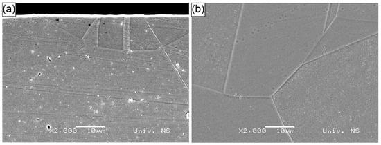
Figure 7.
SEM micrograph of specimen W−532: (a) surface; (b) center.
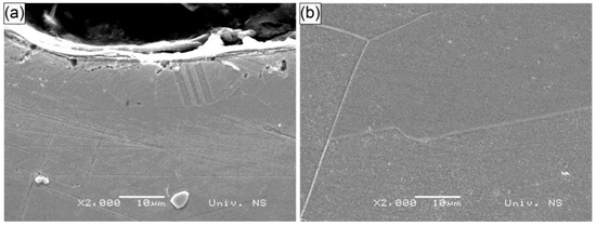
Figure 8.
SEM micrograph of specimen S−532: (a) surface; (b) center.
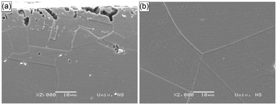
Figure 9.
SEM micrograph of specimen S−1064: (a) surface; (b) center.
The microstructures of the S−532 specimen, showing both the surface and central areas, are presented in Figure 8. Similar to the W−532 specimen, the grains in the center of the S−532 specimen were significantly larger than those at the surface, with grain sizes around 100 µm. However, unlike W−532, the twinning mechanism was more pronounced at the surface of the S−532 specimen, occurring at a slightly shallower depth but resulting in multiple, finer twins. These twins were a consequence of plastic deformation induced by the LSP process.
Despite the shallower depth of the affected region, the surface area showing the twinning was smaller, narrower, and more irregular. Additionally, the surface of the S−532 specimen exhibited pits and damage, which were attributed to the aqua regia etching process rather than the LSP treatment. These surface imperfections were caused by the etchant leaking from the small gap between the specimen and the mounting plastic interface.
The microstructure of the S−1064 specimen, shown in Figure 9, exhibited similar behavior to the previously analyzed specimens, W−532 and S−532. The base material microstructure, depicted in Figure 9b, showed a grain size comparable to that observed in the other specimens. At the surface, refined grains were visible, some of which were likely the result of the twinning process, forming a relatively well-defined surface layer. As with the S−532 specimen, large pits were present on the surface, which were attributed to the effects of the aqua regia etching process during metallographic preparation.
4. Discussion
In this study, the LSP process was applied to an annealed In-718 base material using various confinements, including water as the traditional material and three types of gel-like materials, at two commonly used wavelengths, 532 nm and 1064 nm. In addition to residual stress measurements, microhardness and microstructures were examined both at the surface and in the central section of the specimens.
Water confinement proved to be effective when used in conjunction with both wavelengths used, 532 and 1064 nm. A higher compressive residual stress was obtained with 532 nm, which aligns with findings reported in [32]. This is confirmed by the results of microhardness, where a higher rise was obtained with the 532 nm wavelength. This result is in accordance with microstructures, which show considerable refinement in the surface layer compared to the central section. The refinement observable on the SEM, reached the maximum of 25 µm, which is comparable to the value of 20–30 µm obtained by Zhang et al. [33] who applied the LSP process to a AW7075-T6 alloy and higher than in the work by Li et al. [34], who obtained 1 µm in a K417 nickel-based alloy. The results show that the average grain size on the peened surface of the specimen was refined to 20–30 μm after LSP, and a residual compressive stress layer with a thickness of approximately 0.5 mm was induced on the surface.
The second confinement type, Sikaflex, proved ineffective when applied with the 532 nm wavelength, resulting in only a moderate increase in microhardness near the surface. However, there was some partial grain refinement at the surface, which, similar to the effect with water confinement, occurred in the form of twinning. When applied with the 1064 nm wavelength, clear compressive stresses appeared at the surface. These stresses, however, were lower than those achieved with water confinement at 532 nm, but higher than those obtained with water confinement at 1064 nm. The microhardness was the highest among all the specimens tested, reaching nearly 300 HV0.05, but the increased microhardness was observed at a shallower depth compared to the W-532 specimen.
Le Bras et al. [32] also demonstrated the successful application of the transparent acrylate-based polymer tape; however, gels can provide better coverage of the surface profile and are quicker to be applied in industrial conditions.
Finally, when considering the last two gel types—ultrasonic gel and Vaseline—they were found to be ineffective in inducing compressive residual stress or in significantly increasing surface microhardness. This is the result of their lower structural integrity compared to Sikaflex. In addition, the harder Sikaflex (48 Shore A [35]) behaves similarly to typical adhesive tapes with the hardness range of 40 to 95 Shore A [36] and is closer to the polymer and glass, rendering the wavelength of 1064 nm more effective compared to the 532 nm wavelength. Furthermore, Sikaflex crystal gel is adhesive as well, which gives an additional contribution to this gel’s superiority compared to the other two tested gels. That is particularly important when higher-surface-roughness specimens are LSP-treated, such as additively manufactured specimens in industrial applications with Ra = 8–13.6 µm, which is considerably higher compared to milled specimens (Ra = 0.23–0.78 µm) [37].
Upon analyzing the microstructure, it can be concluded that the grain refinement, compared to the relatively coarse grain structure resulting from the annealing process applied prior to LSP, is closely related to the formation of twins. Twinning, which results in a mirror-image microstructure, occurs when atoms slide past each other due to localized plastic deformation caused by the high-pressure pulse effects, or the mechanical shock waves from the high-pressure plasma [38].
Twinning typically occurs when the applied stress is not aligned with the slip direction or when the material is subjected to high strain rates—both of which apply to the LSP process. Additionally, twinning is more common in materials with specific crystal structures, such as face-centered cubic (FCC) or hexagonal close-packed (HCP) [39,40]. Since Inconel alloys have a typical FCC crystal structure, combined with high strain rates and localized deformation, twinning becomes an important additional deformation mechanism. This contributes to the material’s improved mechanical properties, such as the enhanced microhardness observed in this study, as well as potentially increased resistance to crack initiation, leading to improved fatigue strength [41].
5. Conclusions
Based on the results presented and considering the limitations of this study, the following conclusions can be drawn:
- Compressive residual stress can be achieved by LSP combined with gel confinements. To maximize the effectiveness of gels as a confinement for LSP, a wavelength of 1064 nm is preferred over 532 nm.
- The effectiveness of the optimal gel at 1064 nm is lower in terms of inducing compressive residual stresses compared to water confinement at 532 nm. However, at 1064 nm, gel confinement is more effective than water.
- When considering gel-like confinements, special attention should be given to their adhesive properties and structural integrity to ensure they are not significantly affected by the laser or the interaction with the specimen surface. This is particularly important for cast, welded, or additively manufactured specimens, in addition to rolled specimens.
- Microhardness follows the trends of residual stress, particularly in terms of the depth of increased microhardness, rather than the maximal microhardness value. Water confinement at 532 nm resulted in a greater depth of increased microhardness compared to the optimal gel at 1064 nm. Microhardness values at greater depths were similar across all specimens, reflecting the annealing process conducted prior to the LSP treatment.
- The primary mechanisms for increasing surface microhardness are grain refinement and twinning in the surface layer. This is facilitated by the FCC structure of the base material and the high strain rate of the LSP process.
Therefore, gels can serve as a viable alternative to water, although they are less effective both in inducing compressive stresses and achieving depth compared to water, particularly for applications sensitive to water due to the presence of sensors or electronics. Future work will encompass a deeper analysis of other types of adhesive transparent gels, as well as the influence of LSP on fatigue and corrosion, supported by EBSD (electron backscatter diffraction).
Author Contributions
Conceptualization and writing, S.B.; methodology, S.B., D.R., L.K. and S.Z.; investigation, M.P., D.R., P.J. and F.C.; formal analysis, M.P., P.J., F.C. and L.K.; writing—original draft preparation, M.D. and S.K.; writing—review and editing, M.D. and S.K.; and supervision, S.Z. All authors have read and agreed to the published version of the manuscript.
Funding
This research received funding from the regional project funded by the Provincial Secretary for Higher Education and Scientific Research, Vojvodina, Serbia, through project with grant agreement No. 000838124 2024 09418 003 000 000 001 04 002. In addition, support was provided by the Ministry of Science, Technological Development, and Innovation (contract No. 451-03-136/2025-03/200156) and the Faculty of Technical Sciences, University of Novi Sad, through project “Scientific and Artistic Research Work of Researchers in Teaching and Associate Positions at the Faculty of Technical Sciences, University of Novi Sad, 2025” (No. 01-50/295).
Institutional Review Board Statement
Not applicable.
Informed Consent Statement
Not applicable.
Data Availability Statement
The original contributions presented in this study are included in the article. Further inquiries can be directed to the corresponding author.
Acknowledgments
The authors gratefully acknowledge research support by the project entitled “Materials Science, Joining, and Allied Technologies in Production Engineering” from the Department of Production Engineering, Faculty of Technical Sciences, Novi Sad, Serbia. In addition, this work was co-funded by the European Union and the state budget of the Czech Republic under the project LasApp CZ.02.01.01/00/22_008/0004573.
Conflicts of Interest
The authors declare no conflicts of interest. The funders had no role in the design of the study; in the collection, analyses, or interpretation of data; in the writing of the manuscript; or in the decision to publish the results.
References
- Wang, Z.M.; Jia, Y.F.; Zhang, X.C.; Fu, Y.; Zhang, C.C.; Tu, S.T. Effects of Different Mechanical Surface Enhancement Techniques on Surface Integrity and Fatigue Properties of Ti-6Al-4V: A Review. Crit. Rev. Solid State Mater. Sci. 2019, 44, 445–469. [Google Scholar] [CrossRef]
- Pavan, M.; Furfari, D.; Ahmad, B.; Gharghouri, M.A.; Fitzpatrick, M.E. Fatigue Crack Growth in a Laser Shock Peened Residual Stress Field. Int. J. Fatig. 2019, 123, 157–167. [Google Scholar] [CrossRef]
- Wan, Z.D.; Dai, W.; Guo, W.; Jia, Q.; Zhang, H.Q.; Xue, J.L.; Lin, L.C.; Peng, P. Improved Corrosion Resistance of Ni-Base Alloy 600 Welded Joint by Laser Shock Peening. J. Manuf. Process. 2022, 80, 718–728. [Google Scholar] [CrossRef]
- See, D.W.; Dulaney, J.L.; Clauer, A.H.; Tenaglia, R.D. The Air Force Manufacturing Technology Laser Peening Initiative. Surf. Eng. 2002, 18, 32–36. [Google Scholar] [CrossRef]
- Li, K.M.; Cai, Y.; Yu, Z.; Hu, J. Formation Mechanism of Residual Stress Hole under Different Pulse Durations and Shock Pressure Distributions in Ti6Al4V Alloy during Laser Peen Texturing. Opt. Laser Technol. 2020, 130, 10636. [Google Scholar] [CrossRef]
- Deng, W.; Wang, C.; Lu, H.; Meng, X.; Wang, Z.; Lv, J.; Luo, K.; Lu, J. Progressive Developments, Challenges and Future Trends in Laser Shock Peening of Metallic Materials and Alloys: A Comprehensive Review. Int. J. Mach. Tools Manuf. 2023, 191, 104061. [Google Scholar] [CrossRef]
- Peyre, P.; Fabbro, R. Laser Shock Processing: A Review of the Physics and Applications. Opt. Quantum Electron. 1995, 27, 1213–1229. [Google Scholar] [CrossRef]
- Sun, W.T.; Qiao, X.G.; Zheng, M.Y.; He, Y.; Hu, N.; Xu, C.; Gao, N.; Starink, M.J. Exceptional Grain Refinement in a Mg Alloy During High Pressure Torsion Due to Rare Earth Containing Nanosized Precipitates. Mater. Sci. Eng. A 2018, 728, 115–123. [Google Scholar] [CrossRef]
- Ding, K.; Ye, L. Laser Shock Peening Performance and Process Simulation; Woodhead Publishing Limited: Cambridge, UK, 2006. [Google Scholar]
- Sticchi, M.; Staron, P.; Sano, Y.; Meixer, M.; Klaus, M.; Rebelo-Kornmeier, J.; Huber, N.; Kashaev, N. A Parametric Study of Laser Spot Size and Coverage on the Laser Shock Peening-Induced Residual Stress in Thin Aluminium Samples. J. Eng. 2015, 2015, 97–105. [Google Scholar] [CrossRef]
- Balos, S.; Pecanac, M.; Rajnovic, D.; Barenyi, I.; Chochlikova, H.; Zlatanovic, D.L.; Bergmann, J.P.; Knezev, M.; Radisic, S.; Majerik, J. Influence of Laser Shock Peening on the Bobbin Tool Friction Stir-Welded AW6060 Alloy. Materials 2025, 18, 247. [Google Scholar] [CrossRef]
- Cao, X.; Wu, J.; Zhong, G.; Wu, J.; Chen, X. Laser Shock Peening: Fundamentals and Mechanisms of Metallic Material Wear Resistance Improvement. Materials 2024, 17, 909. [Google Scholar] [CrossRef] [PubMed]
- Jing, Y.; Fang, X.; Xi, N.; Chang, T.; Duan, Y.; Huang, K. Improved Tensile Strength and Fatigue Properties of Wire-Arc Additively Manufactured 2319 Aluminum Alloy by Surface Laser Shock Peening. Mater. Sci. Eng. A 2023, 864, 144599. [Google Scholar] [CrossRef]
- Ye, C.; Suslov, S.; Kim, B.J.; Stach, E.A.; Cheng, G.J. Fatigue Performance Improvement in AISI 4140 Steel by Dynamic Strain Aging and Dynamic Precipitation during Warm Laser Shock Peening. Acta Mater. 2011, 59, 1014–1025. [Google Scholar] [CrossRef]
- Huang, S.; Sheng, J.; Wang, Z.W.; Meng, X.K.; Lu, J.Z.; Hu, X.Q.; Zhou, J.Z. Finite Element and Experimental Analysis of Elevated-Temperature Fatigue Behavior of IN718 Alloy Subjected to Laser Peening. Int. J. Fatig. 2020, 131, 105337. [Google Scholar] [CrossRef]
- Wang, C.Y.; Luo, K.Y.; Bu, X.Y.; Su, Y.Y.; Cai, J.; Zhang, Q.L.; Lu, J.Z. Laser Shock Peening-Induced Surface Gradient Stress Distribution and Extension Mechanism in Corrosion Fatigue Life of AISI 420 Stainless Steel. Corros. Sci. 2020, 177, 109027. [Google Scholar] [CrossRef]
- Wang, C.Y.; Luo, K.Y.; Cai, J.; Lu, J.Z. Obvious Improvement in Electrochemical and Long-Term Immersion Corrosion Resistance of AISI 420 Martensitic Stainless Steel Using Laser Shock Peening. Corros. Sci. 2022, 209, 110688. [Google Scholar] [CrossRef]
- Martí-López, R.; Ocaña, E.; Piñeiro, A.; Asensio, A. Laser Peening Induced Shock Waves and Cavitation Bubbles in Water Studied by Optical Schlieren Visualization. Phys. Procedia 2011, 12, 442–451. [Google Scholar] [CrossRef][Green Version]
- Claudia, P.; Glaser, D.; Bedekar, R.D. Water Confinement Influences on the Laser Shock Peening Process. In Proceedings of the 30th International Congress on High-Speed Imaging and Photonics, Pretoria, South Africa, 16–21 September 2012; CSIR International Conference Centre: Pretoria, South Africa, 2012; Volume 978-0-620-56214-0. [Google Scholar]
- Sandmann, P.; Keller, S.; Kashaev, N.; Ghouse, S.; Hooper, P.A.; Klusemann, B.; Davies, C.M. Influence of Laser Shock Peening on the Residual Stresses in Additively Manufactured 316L by Laser Powder Bed Fusion: A Combined Experimental–Numerical Study. Addit. Manuf. 2022, 60, 103204. [Google Scholar] [CrossRef]
- Wu, X.; Duan, Z.; Song, H.; Wei, Y.; Wang, X.; Huang, C. Shock Pressure Induced by Glass-Confined Laser Shock Peening: Experiments, Modeling and Simulation. J. Appl. Phys. 2011, 110, 053112. [Google Scholar] [CrossRef]
- Hong, X.; Wang, S.; Guo, D.; Wu, H.; Wang, J.; Dai, Y.; Xia, X.; Xie, Y. Confining Medium and Absorptive Overlay: Their Effects on a Laser-Induced Shock Wave. Opt. Lasers Eng. 1998, 29, 447–455. [Google Scholar] [CrossRef]
- Le Bras, C.; Rondepierre, A.; Seddik, R.; Scius-Bertrand, M.; Rouchausse, Y.; Videau, L.; Fayolle, B.; Gervais, M.; Morin, L.; Valadon, S. Laser Shock Peening: Toward the Use of Pliable Solid Polymers for Confinement. Metals 2019, 9, 793. [Google Scholar] [CrossRef]
- Kalentics, N.; Boillat, E.; Peyre, P.; Ćirić-Kostić, S.; Bogojević, N.; Logé, R.E. Tailoring Residual Stress Profile of Selective Laser Melted Parts by Laser Shock Peening. Addit. Manuf. 2017, 16, 90–97. [Google Scholar] [CrossRef]
- Kalentics, N.; de Seijas, M.O.V.; Griffiths, S.; Leinenbach, C.; Loge, R.E. 3D Laser Shock Peening–A New Method for Improving Fatigue Properties of Selective Laser Melted Parts. Addit. Manuf. 2020, 33, 101112. [Google Scholar] [CrossRef]
- Kalentics, N.; Burn, A.; Cloots, M.; Loge, R.E. 3D Laser Shock Peening as a Way to Improve Geometrical Accuracy in Selective Laser Melting. Int. J. Adv. Manuf. Technol. 2019, 101, 1247–1254. [Google Scholar] [CrossRef]
- Kalentics, N.; Sohrabi, N.; Tabasi, H.G.; Griffiths, S.; Jhabvala, J.; Leinenbach, C.; Burn, A.; Loge, R.E. Healing Cracks in Selective Laser Melting by 3D Laser Shock Peening. Addit. Manuf. 2019, 30, 100881. [Google Scholar] [CrossRef]
- Zhang, Y.; Besshi, T.; Tsuyama, M.; Heya, M.; Nakano, H. Pliable Solid Medium as a Plasma Confinement Layer for Laser Peening. J. Laser Appl. 2023, 35, 012014. [Google Scholar] [CrossRef]
- ASTM F3055-14a; Standard Specification for Additive Manufacturing File Format. ASTM International: West Conshohocken, PA, USA, 2021.
- Kaufman, J.; Špirit, Z.; Vasudevan, V.K.; Steiner, M.A.; Mannava, S.R.; Brajer, J.; Pína, L.; Mocek, T. Effect of Laser Shock Peening Parameters on Residual Stresses and Corrosion Fatigue of AA5083. Metals 2021, 11, 1635. [Google Scholar] [CrossRef]
- Trivkovic, M.; Maksimovic, N.; Pecanac, M.; Stojisic, N.; Dramicanin, M.; Rajnovic, D.; Balos, S. Laser Shock Peening of AISI 316L Austenitic Stainless Steel with Various Confinements. In Proceedings of the 15th International Conference on Flexible Technologies, Novi Sad, Serbia, 24–26 September 2024; pp. 181–184. [Google Scholar]
- Le Bras, C.; Rondepierre, A.; Ayad, M.; Rouchausse, Y.; Gervais, M.; Valadon, S.; Berthe, L. Novel Confinement Possibility for Laser Shock: Use of Flexible Polymer Confinement at 1064 nm Wavelength. Metals 2021, 11, 1467. [Google Scholar] [CrossRef]
- Zhang, J.; Cheng, X.; Xia, Q.; Yan, C. Strengthening Effect of Laser Shock Peening on 7075-T6 Aviation Aluminum Alloy. Adv. Mech. Eng. 2014, 6, 1687814014528788. [Google Scholar] [CrossRef]
- Li, Y.; Zhou, L.; He, W.; He, G.; Wang, X.; Nie, X.; Wang, B.; Luo, S.; Li, Y. The Strengthening Mechanism of a Nickel-Based Alloy after Laser Shock Processing at High Temperatures. Sci. Technol. Adv. Mater. 2013, 14, 055010. [Google Scholar] [CrossRef]
- Sika, A.G. Sikaflex-112 Crystal Clear Gel; Sika AG: Zürich, Switzerland, 2024; Available online: https://gcc.sika.com/dms/getdocument.get/219c9760-5cb4-4c96-a251-4f10136ab517/sikaflex-112-crystalclear.pdf (accessed on 22 April 2025).
- 3M. 3M Acrylic Plus Tapes; Brochure; 3M: St Paul, MN, USA, 2020; Available online: https://multimedia.3m.com/mws/media/493536O/3m-acrylic-plus-weatherstrip-tape.pdf (accessed on 22 April 2025).
- Taşcıoğlu, E.; Kaynak, Y.; Sharif, S.; Pıtır, F.; Suhaimi, M.A. Machining-Induced Surface Integrity of Inconel 718 Alloy Fabricated by Powder Bed Fusion Additive Manufacturing under Various Laser Processing Parameters. Mach. Sci. Technol. 2022, 26, 49–71. [Google Scholar] [CrossRef]
- Radziejewska, J.; Strzelec, M.; Ostrowski, R.; Sarzyński, A. Experimental Investigation of Shock Wave Pressure Induced by a ns Laser Pulse under Varying Confined Regimes. Opt. Lasers Eng. 2020, 126, 105913. [Google Scholar] [CrossRef]
- Schneider, J.; Farris, L.; Nolze, G.; Reinsch, S.; Cios, G.; Tokarski, T.; Thompson, S. Microstructure Evolution in Inconel 718 Produced by Powder Bed Fusion Additive Manufacturing. J. Manuf. Mater. Process. 2022, 6, 20. [Google Scholar] [CrossRef]
- Zhang, H.; Wei, B.; Ou, X.; Ni, S.; Zhou, K.; Song, M. Dislocation Induced FCC Twinning at the HCP/FCC Interfaces in a Deformed Ti-5at.%Al Alloy: Experiments and Simulations. J. Phys. Chem. Solids 2022, 169, 110835. [Google Scholar] [CrossRef]
- Deng, W.; Wang, C.; Lu, H.; Xu, X.; Luo, K.; Lu, J. Fatigue Crack Initiation and Growth of Laser Shock Peened 2Cr13 Martensitic Stainless Steel as a Function of the Coverage Layer. Int. J. Fatig. 2023, 175, 107792. [Google Scholar] [CrossRef]
Disclaimer/Publisher’s Note: The statements, opinions and data contained in all publications are solely those of the individual author(s) and contributor(s) and not of MDPI and/or the editor(s). MDPI and/or the editor(s) disclaim responsibility for any injury to people or property resulting from any ideas, methods, instructions or products referred to in the content. |
© 2025 by the authors. Licensee MDPI, Basel, Switzerland. This article is an open access article distributed under the terms and conditions of the Creative Commons Attribution (CC BY) license (https://creativecommons.org/licenses/by/4.0/).