
Effects of TC4 Thickness on the Penetration Resistance Behavior of Ti-Al3Ti Metal–Intermetallic Laminated Composites


Abstract
1. Introduction
2. Materials and Methods
2.1. Material Preparation
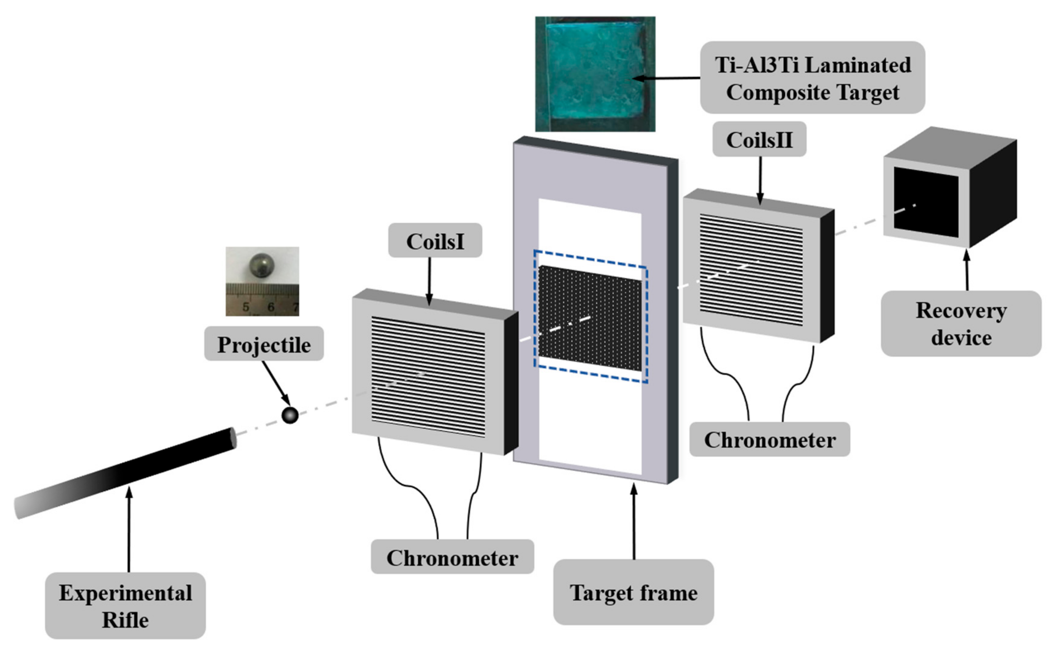
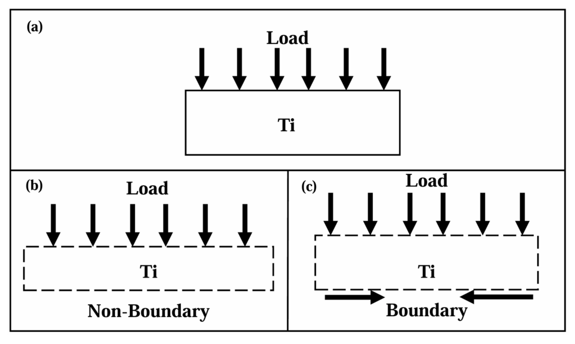
2.2. Anti-Penetration Experiments
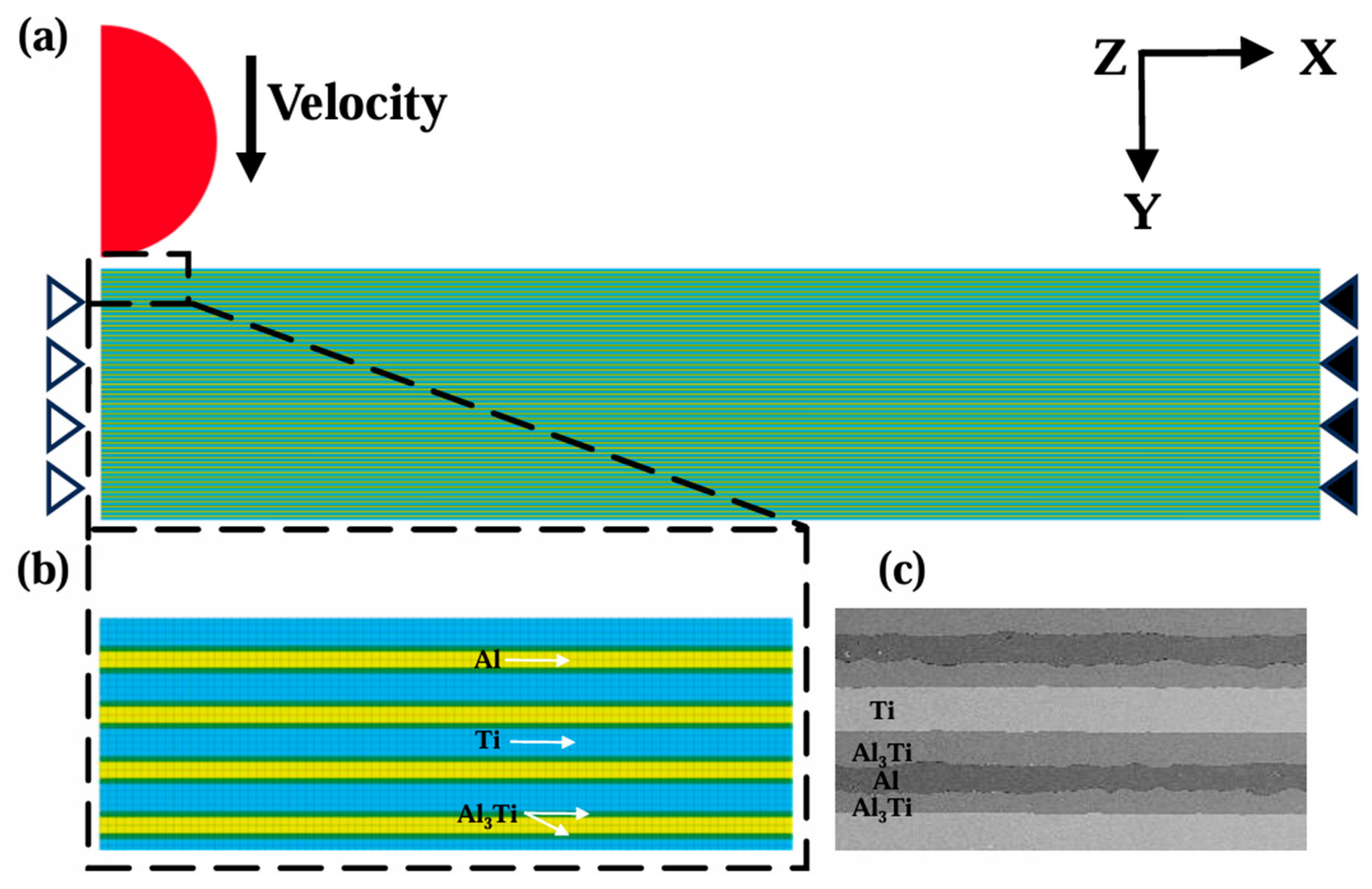
2.3. Finite Element Simulations
2.4. Constitutive Models and Parameters
3. Results and Discussion
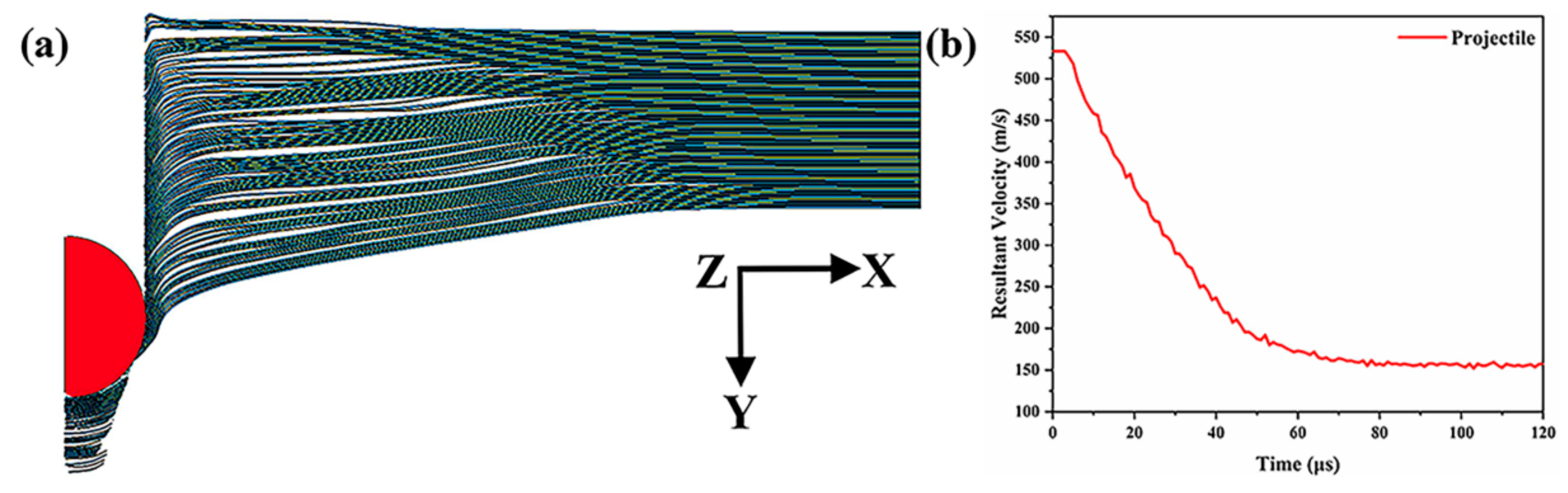
3.1. Model Validation
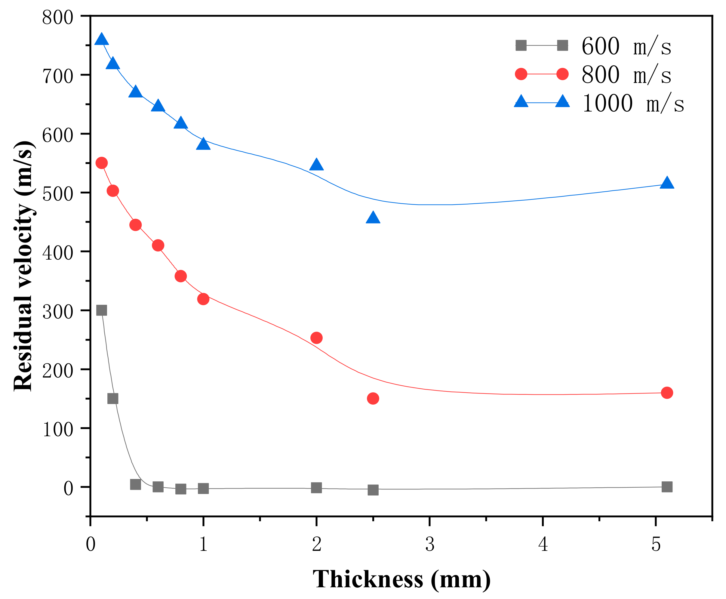
3.2. Anti-Penetration Property of Material
3.3. Influence of Ti Layer Thickness on Penetration Process
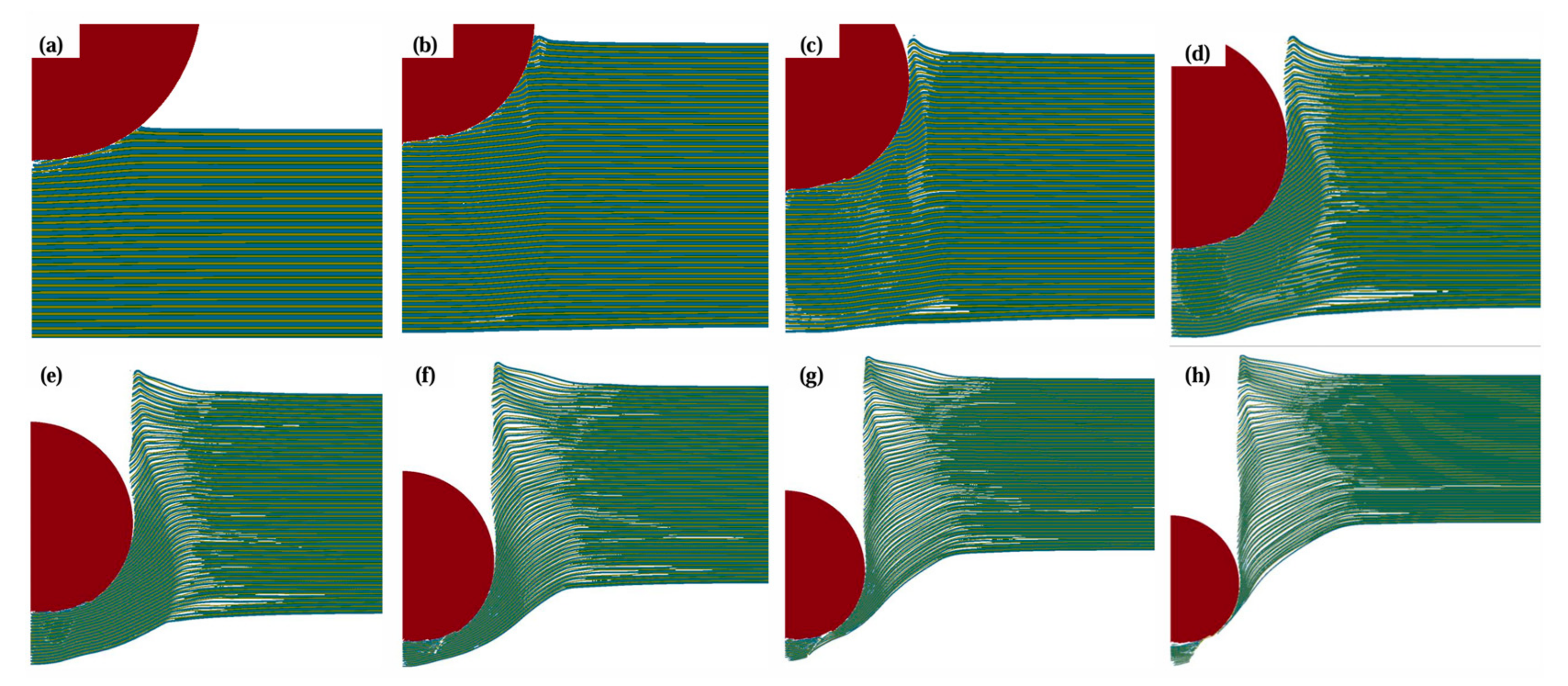
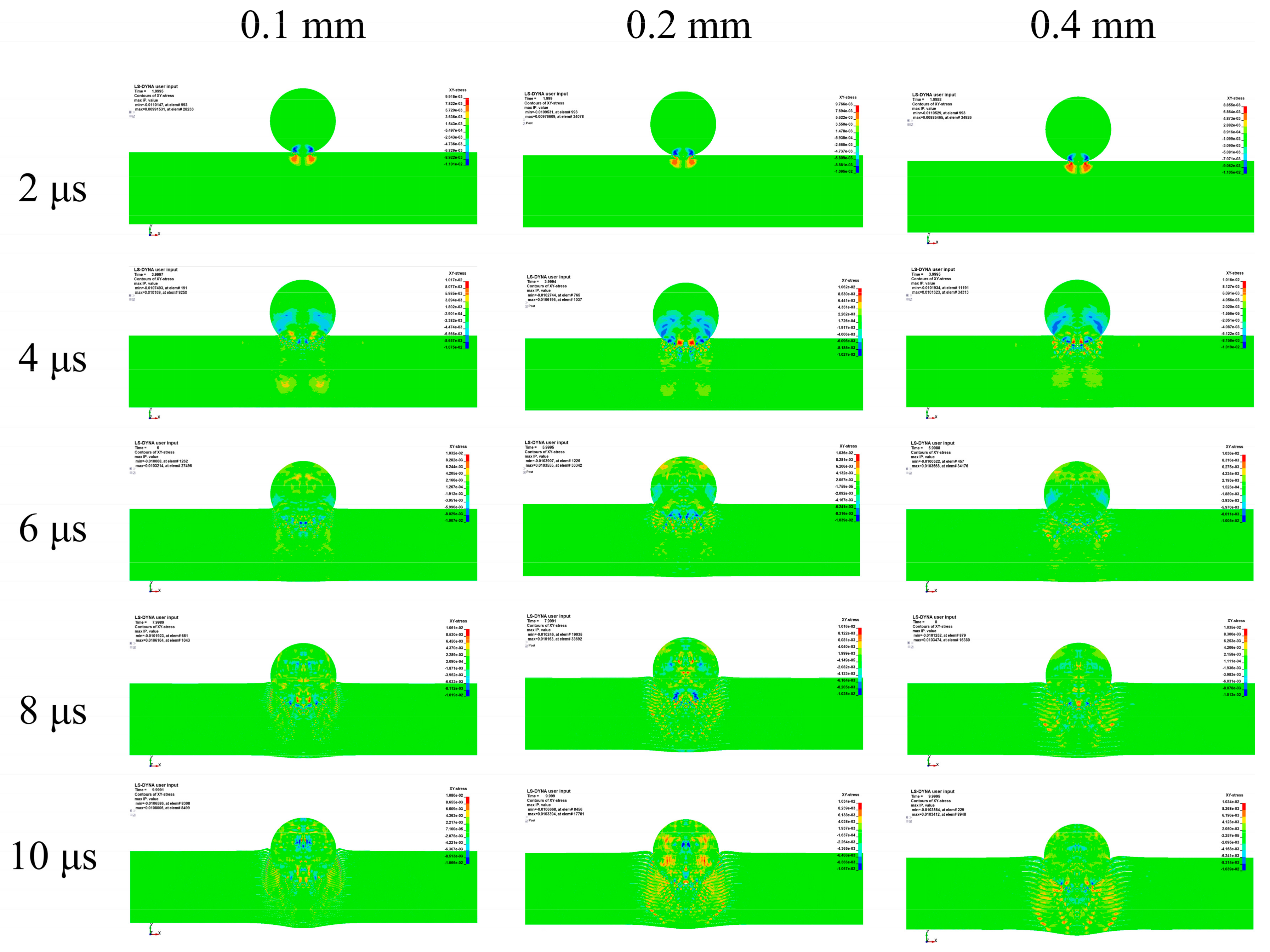
3.3.1. Cratering Stage
3.3.2. Stable Penetration Stage
3.3.3. Perforation Stage
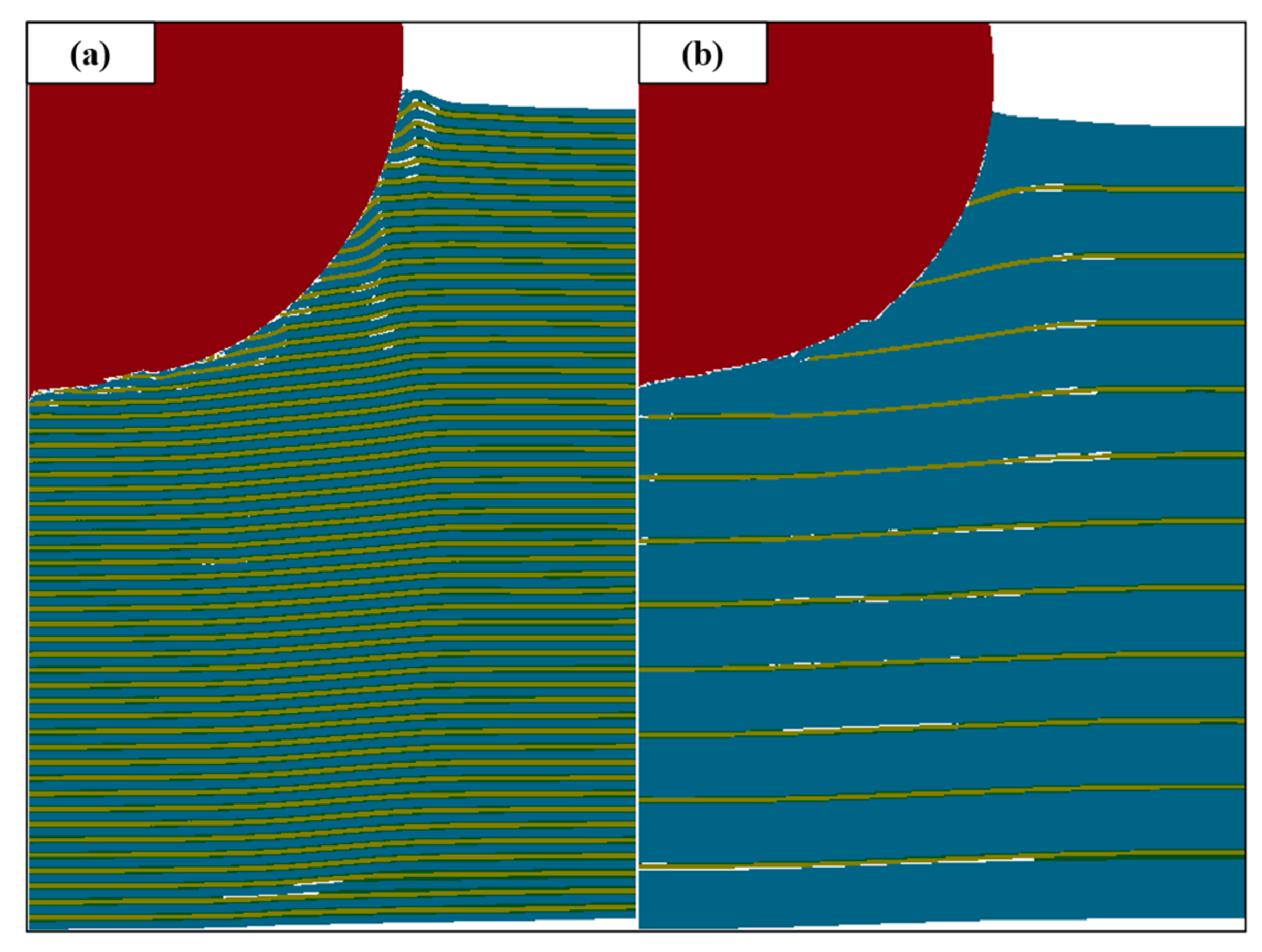
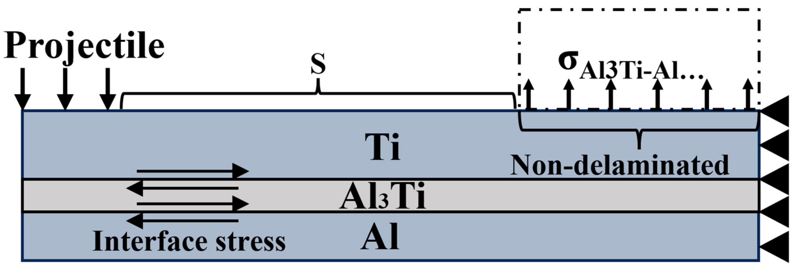
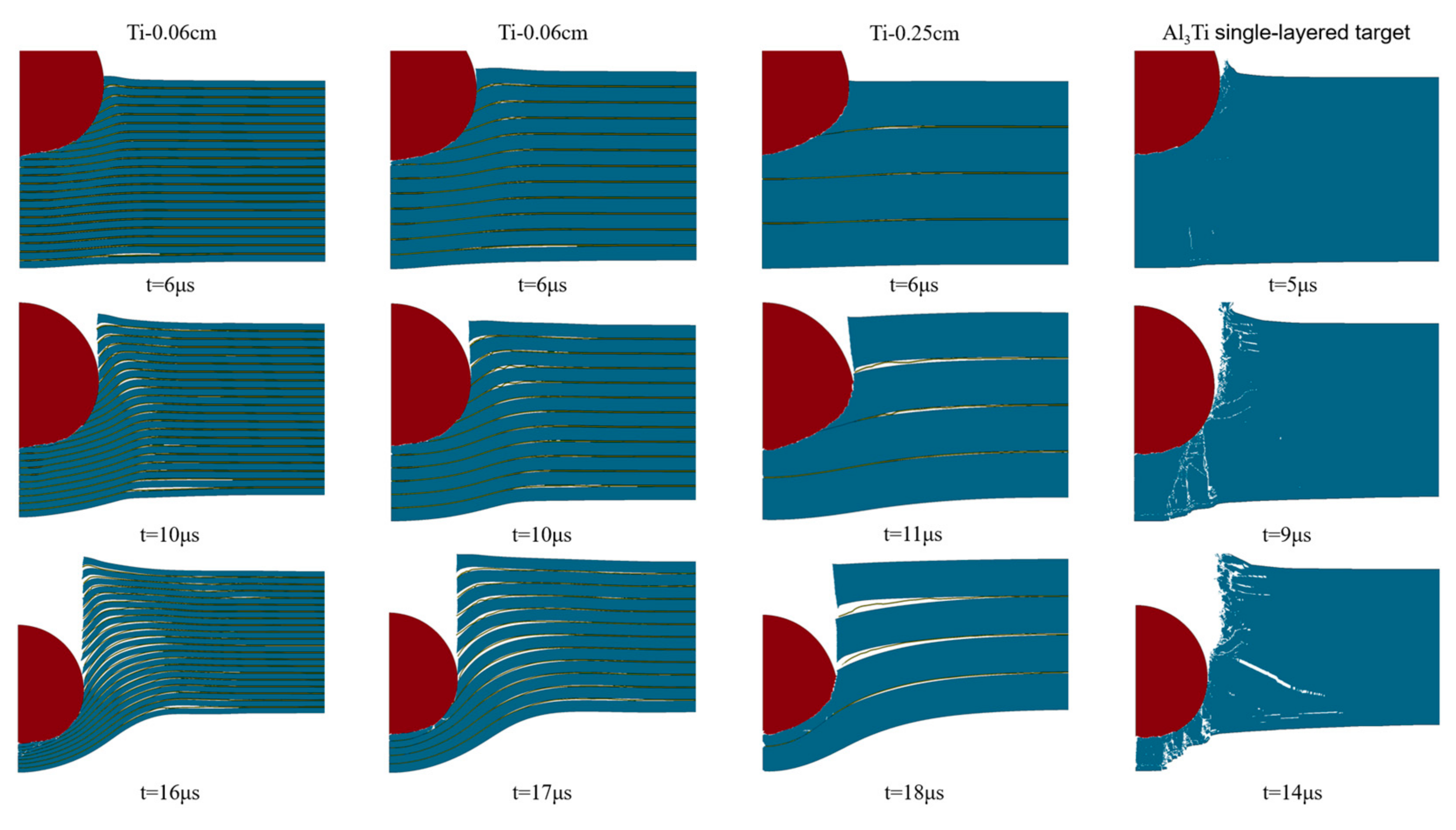
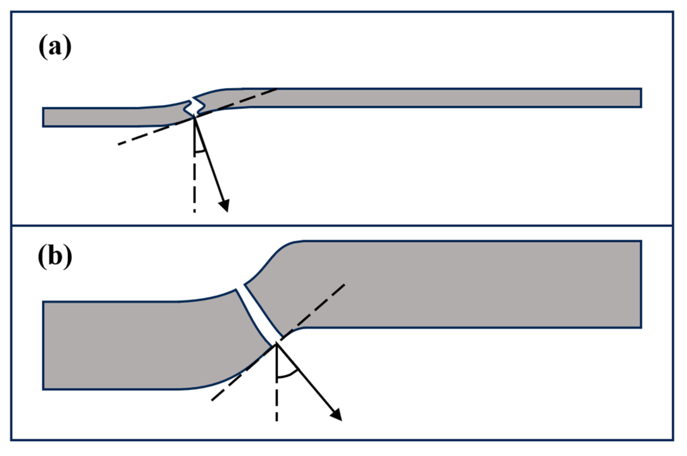
3.3.4. Anti-Penetration Mechanism of Ti-Al3Ti MIL Target with Different Thicknesses of Ti Layer
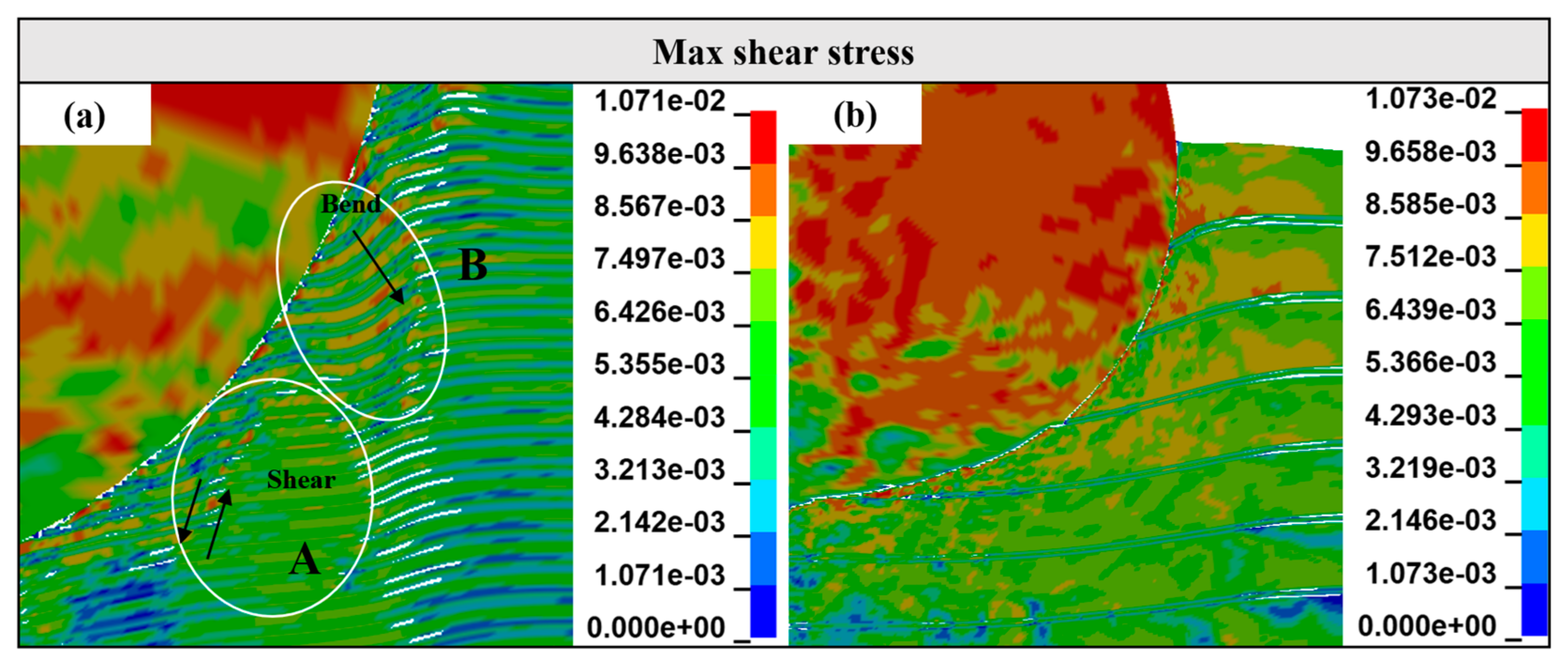
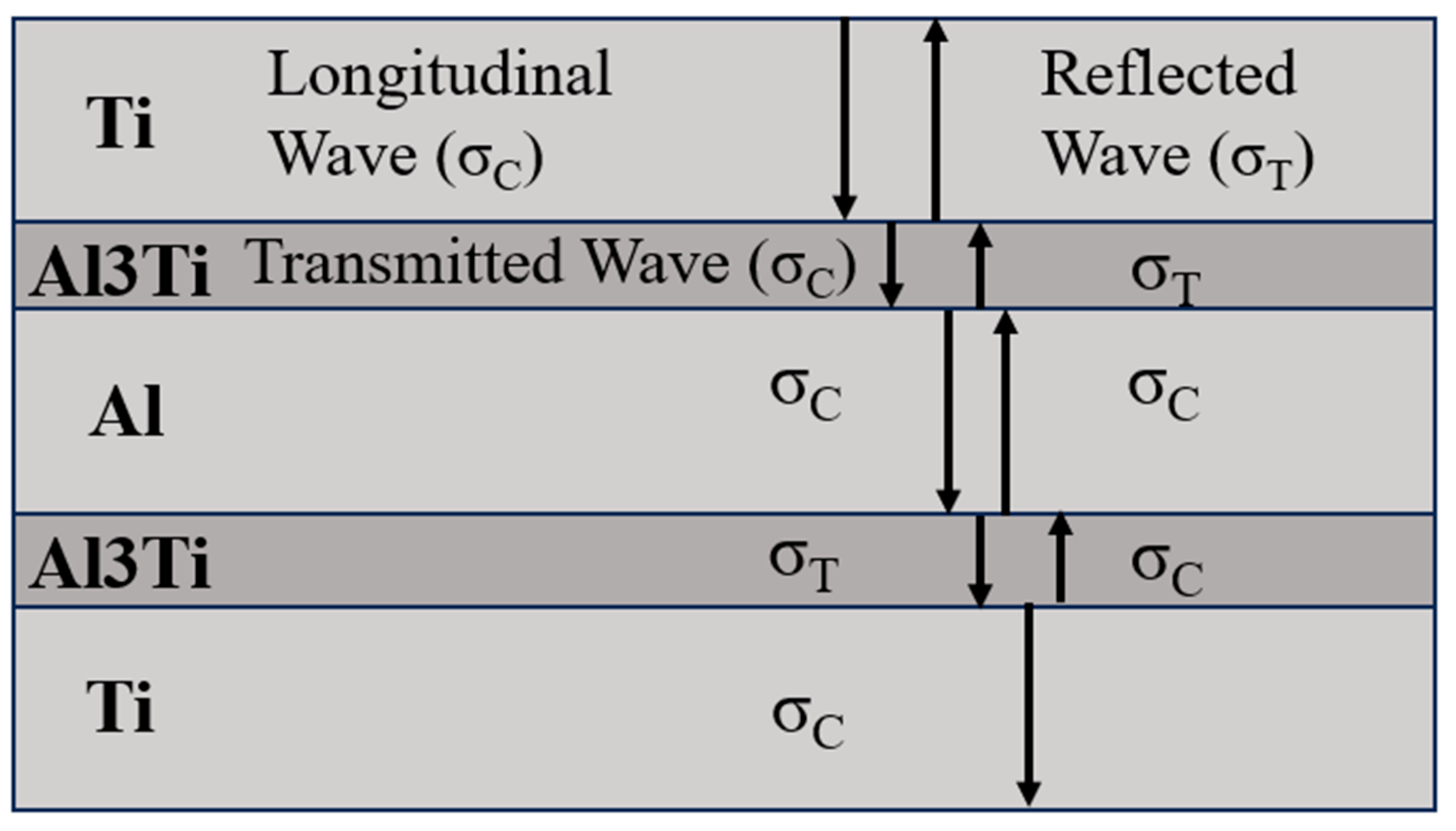
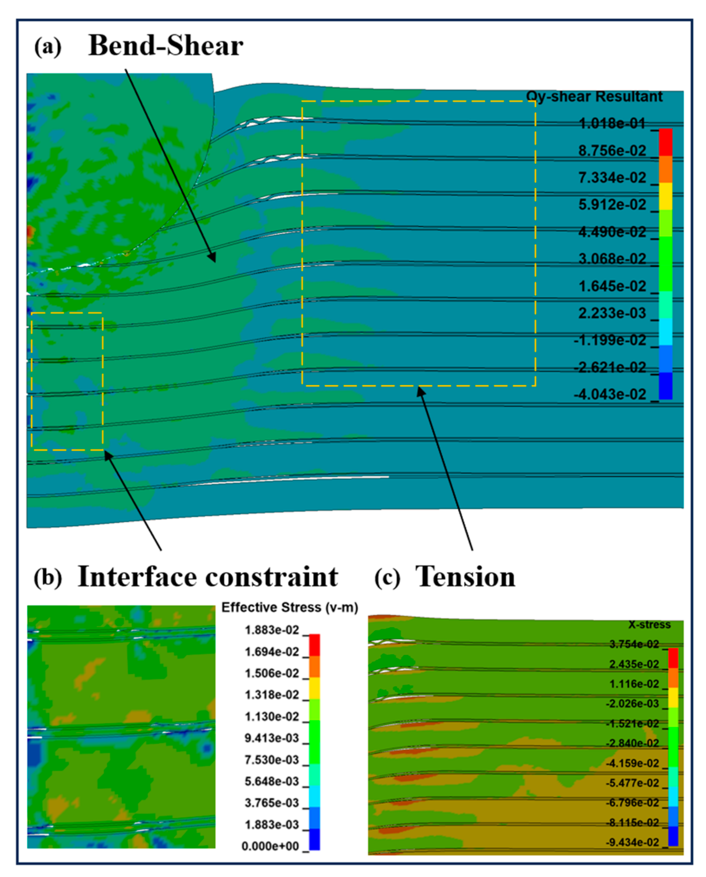
3.4. Analysis of Stress Behavior of Ti-Al3Ti
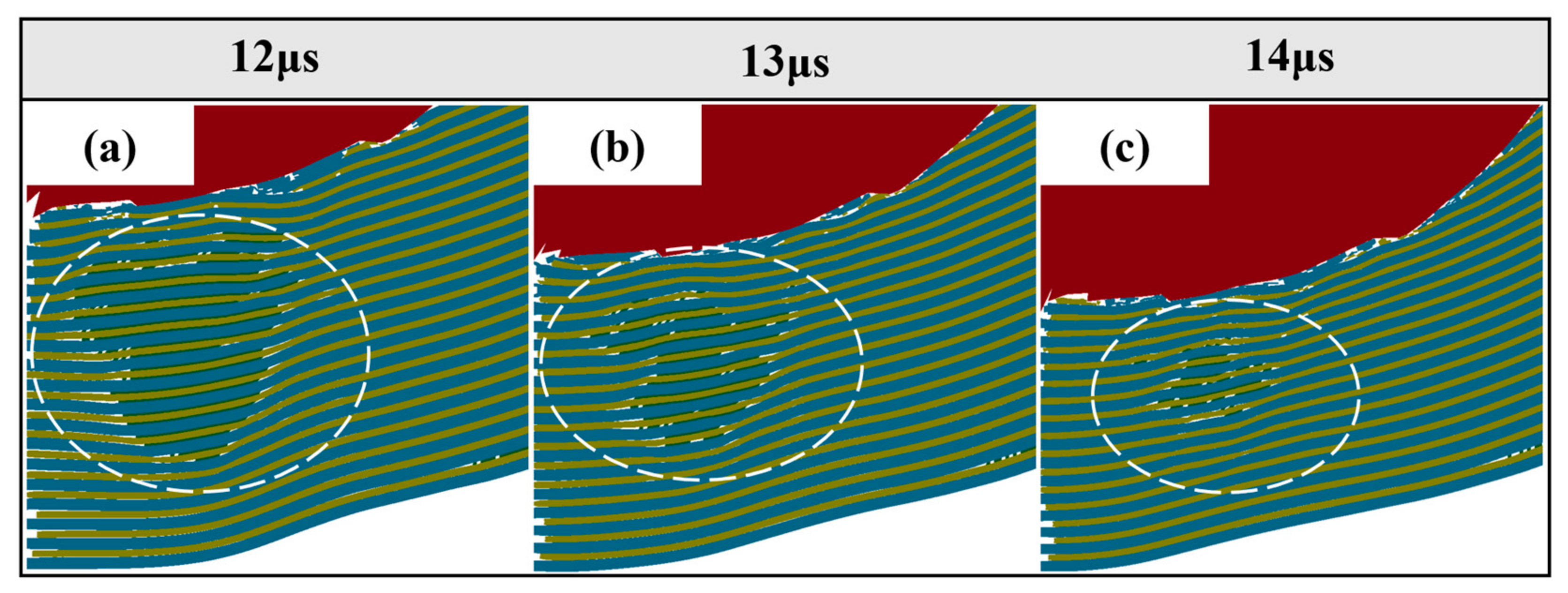
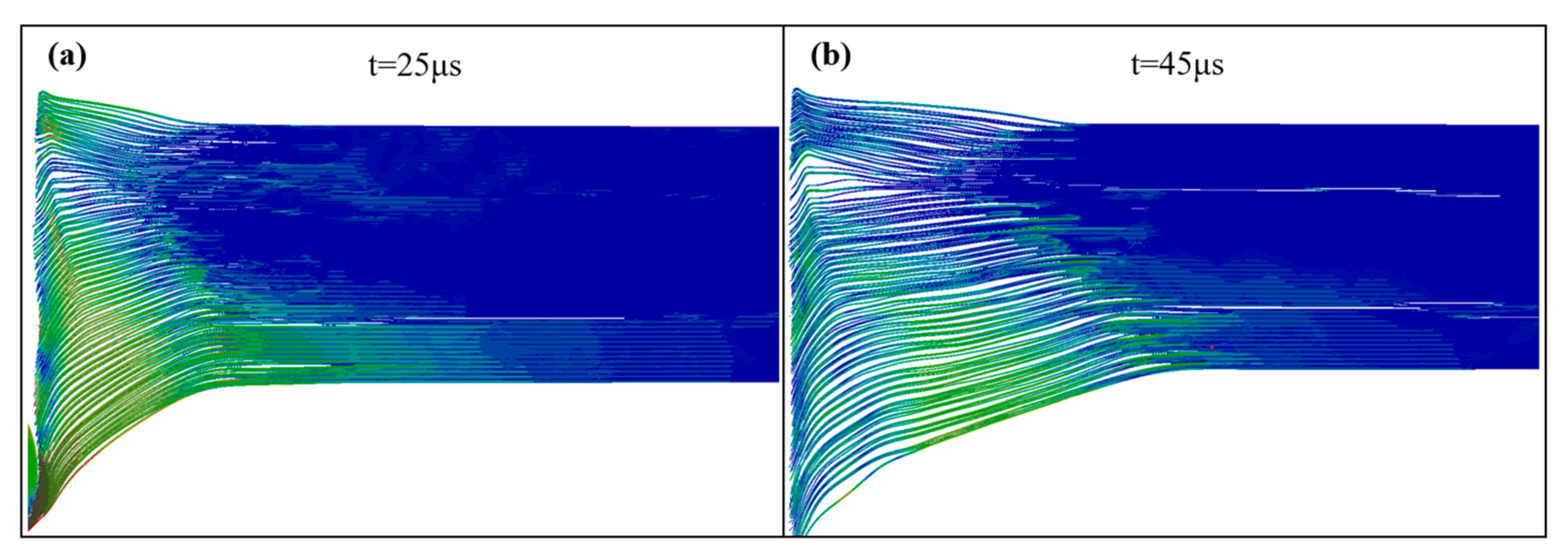
3.5. Crack Propagation and Damage Evolution
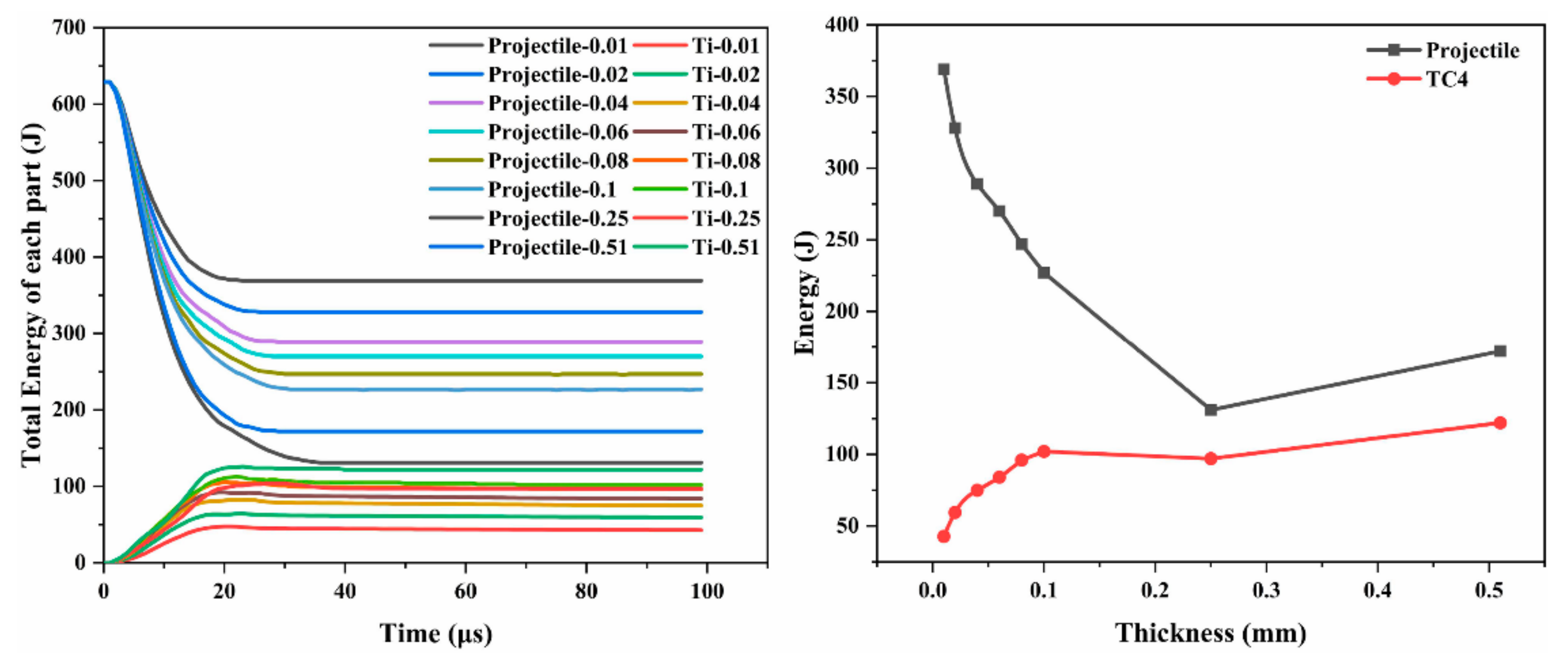
3.6. Energy Behavior of Ti-Al3Ti Target with Different Ti Thicknesses
4. Conclusions
Author Contributions
Funding
Institutional Review Board Statement
Informed Consent Statement
Data Availability Statement
Acknowledgments
Conflicts of Interest
References
- Adharapurapu, R.R.; Vecchio, K.S.; Jiang, F.; Rohatgi, A. Effects of ductile laminate thickness, volume fraction, and orientation on fatigue-crack propagation in Ti-Al3Ti metal-intermetallic laminate composites. Metall. Mater. Trans. A 2005, 36, 1595–1608. [Google Scholar] [CrossRef]
- Grujicic, M.; Snipes, J.; Ramaswami, S. Penetration resistance and ballistic-impact behavior of Ti/TiAl3 metal/intermetallic laminated composites (MILCs): A computational investigation. AIMS Mater. Sci. 2016, 3, 686–721. [Google Scholar] [CrossRef]
- Yu, H.; Fan, Q.B.; Zhu, X.J. Effect of the Layer Sequence on the Ballistic Performance and Failure Mechanism of Ti6Al4V/CP-Ti Laminated Composite Armor. Materials 2020, 13, 3886. [Google Scholar] [CrossRef]
- Zhang, R.; Chao, Z.; Jiang, L.; Han, H.; Han, B.; Du, S.; Luo, T.; Chen, G.; Mei, Y.; Wu, G. Influence of Interface on Mechanical Behavior of Al-B4C/Al Laminated Composites under Quasi-Static and Impact Loading. Materials 2023, 16, 6847. [Google Scholar] [CrossRef]
- Guo, Y.; Ge, Y.; Deng, L.; Wang, C.; Zhou, C.; Gao, T.; Bataev, I.A.; Fan, H.; Zhou, Q.; Chen, P.; et al. Ballistic impact behavior of commercially pure titanium with gradient nanostructure against projectiles with different nose shapes. Int. J. Impact Eng. 2025, 202, 105295. [Google Scholar] [CrossRef]
- Ma, J.; Yuan, M.; Zheng, L.; Wei, Z.; Wang, K. Dynamic Mechanical Properties of Ti–Al3Ti–Al Laminated Composites: Experimental and Numerical Investigation. Metals 2021, 11, 1489. [Google Scholar] [CrossRef]
- Li, X.; Lu, L.; Li, J.; Zhang, X.; Gao, H. Mechanical properties and deformation mechanisms of gradient nanostructured metals and alloys. Nat. Rev. Mater. 2020, 5, 706–723. [Google Scholar] [CrossRef]
- Yuan, M.-n.; Yao, Y.; Han, F.; Le, X.; Shen, X. Effects of Ductile Al on the Anti-penetration Performance of the Ti-Al3Ti Laminated Composites. Results Phys. 2020, 18, 103308. [Google Scholar] [CrossRef]
- Cao, Y.; Zhang, D.-D.; Liu, J.-X.; Liu, K.; Du, J.-U.; He, W.B.; Ma, J. The mechanical performance and a rate-dependent constitutive model for Al3Ti compound. Def. Technol. 2019, 16, 627–634. [Google Scholar] [CrossRef]
- Liu, Y.; Yin, C.; Hu, X.; Yuan, M.-N. Ballistic limit velocity of tungsten alloy spherical fragment penetrating Ti/Al3Ti-laminated composite target plates. Adv. Compos. Lett. 2020, 29. [Google Scholar] [CrossRef]
- Thiyaneshwaran, N.; Selvan, C.P.; Lakshmikanthan, A.; Sivaprasad, K.; Ravisankar, B. Comparison based on specific strength and density of in-situ Ti/Al and Ti/Ni metal intermetallic laminates. J. Mater. Res. Technol. 2021, 14, 1126–1136. [Google Scholar] [CrossRef]
- Zelepugin, S.; Mali, V.; Zelepugin, A.; Ilina, E. Failure of Metallic-Intermetallic Laminate Composites under Dynamic Loading. AIP Conf. Proc. 2011, 1426, 1119. [Google Scholar]
- Zelepugin, S.; Zelepugin, A.; Tolkachev, V. Numerical simulation of multilayer composites failure under dynamic loading. In Proceedings of the ECCOMAS Congress 2016: VII European Congress on Computational Methods in Applied Sciences and Engineering, Crete, Greece, 5–10 June 2016; pp. 334–340. [Google Scholar]
- Khan, S.H.; Sharma, A.P. Influence of metal/composite interface on the damage behavior and energy absorption mechanisms of FMLs against projectile impact. Def. Technol. 2022, 18, 441–456. [Google Scholar] [CrossRef]
- Vecchio, K.S. Synthetic multifunctional metallic-intermetallic laminate composites. JOM 2005, 57, 25–31. [Google Scholar] [CrossRef]
- Bataev, I.A.; Bataev, A.A.; Mali, V.I.; Pavliukova, D.V. Structural and mechanical properties of metallic–intermetallic laminate composites produced by explosive welding and annealing. Mater. Des. 2012, 35, 225–234. [Google Scholar] [CrossRef]
- Zhou, P.; Yuan, M.; Jia, M.; Pei, X.; Wang, Y.; Yang, W.; Wang, H.; Zhao, Y. New strategy for enhancing the strength and toughness of Ti-Al metallic-intermetallic laminated composites: Constructing multiple heterostructures using Ni foil. Prog. Nat. Sci. Mater. Int. 2024, 34, 1173–1183. [Google Scholar] [CrossRef]
- Huang, C.X.; Wang, Y.F.; Ma, X.L.; Yin, S.; Höppel, H.W.; Göken, M.; Wu, X.L.; Gao, H.J.; Zhu, Y.T. Interface affected zone for optimal strength and ductility in heterogeneous laminate. Mater. Today 2018, 21, 713–719. [Google Scholar] [CrossRef]
- Wu, H.; Fan, G. An overview of tailoring strain delocalization for strength-ductility synergy. Prog. Mater. Sci. 2020, 113, 100675. [Google Scholar] [CrossRef]
- Meyers, M.A. Dynamic Behavior of Materials; John Wiley & Sons: Hoboken, NJ, USA, 1994. [Google Scholar]
- GA 950-2019; V50 Test Methods for Ballistic Materials and Products. Ministry of Public Security of the People’s Republic of China: Beijing, China, 2019.
- Johnson, G.R.; Cook, W.H. Fracture characteristics of three metals subjected to various strains, strain rates, temperatures and pressures. Eng. Fract. Mech. 1985, 21, 31–48. [Google Scholar] [CrossRef]
- Johnson, G.R.; Holmquist, T.J. An improved computational constitutive model for brittle materials. AIP Conf. Proc. 1994, 309, 981–984. [Google Scholar]
- Li, J.; Zhang, Q.; Huang, R.; Li, X.; Gao, H. Towards understanding the structure–property relationships of heterogeneous-structured materials. Scr. Mater. 2020, 186, 304–311. [Google Scholar] [CrossRef]
- Li, M.; Wang, K.; Guo, Q.; Tian, X.; Liu, Y.; Wang, K.; Wang, Y.; Hou, H.; Xiong, Z.; Zhao, Y. Synergistic crack inhibition by lamellar structure and graphene nanoplatelets in 2024 Al-GNPs/TC4 laminated metal composites. Mater. Sci. Eng. A 2024, 901, 146347. [Google Scholar] [CrossRef]
- Su, W.; Wang, M.; Guo, F.; Ran, H.; Cheng, Q.; Wang, Q.; Zhu, Y.; Ma, X.; Huang, C. Heterostructure enables anomalous improvement of cryogenic mechanical properties in titanium. Acta Mater. 2024, 273, 119982. [Google Scholar] [CrossRef]
- Carlucci, D.E.; Jacobson, S.S. Ballistics; CRC Press: Boca Raton, FL, USA, 2018. [Google Scholar]
- Cao, Y.; Guo, C.; Zhu, S.; Wei, N.; Javed, R.; Jiang, F. Fracture behavior of Ti/Al3Ti metal-intermetallic laminate (MIL) composite under dynamic loading. Mater. Sci. Eng. A 2015, 637, 235–242. [Google Scholar] [CrossRef]
- Cao, S.; Fan, J. Numerical model for penetration process of a deformable projectile into ductile metallic target plate considering the interaction of projectile and target. Int. J. Impact Eng. 2025, 195, 105107. [Google Scholar] [CrossRef]
- Wang, X.; Yuan, M.; Miao, Y.; Wei, Z. Stress wave propagation characteristics and impact resistance of laminated composites under impact loading. Mech. Adv. Mater. Struct. 2024, 31, 1822–1831. [Google Scholar] [CrossRef]


| Materials | Composition (wt.%) |
|---|---|
| TI foil | Ti: balance, Al: 5.50–6.80, V: 3.50–4.50, Fe ≤ 0.30, O ≤ 0.20, C ≤ 0.10, N ≤ 0.05, H ≤ 0.01 |
| Al foil | Al: 99.60, Fe: 0.35, Si: 0.25, Cu: 0.05, Zn: 0.05, V: 0.05, Mg: 0.03, Ti: 0.35 |
| Thickness and Number of Al Layers (mm × n) | Thickness and Number of Al3Ti Layers (mm × n) | Thickness and Number of Ti Layers (mm × n) | The Element Number of the Target |
|---|---|---|---|
| 0.06 × 51 | 0.02 × 10² | 0.1 × 52 | 219800 |
| ρ (g.cm−3) | E (GPa) | A (GPa) | B (GPa) | c | m | n | TMelt (K) | ||
|---|---|---|---|---|---|---|---|---|---|
| Al | 2.70 | 135.00 | 0.33 | 989.00 | 70.00 | 0.00 | 1.00 | 0.37 | 300.00 |
| Ti | 4.428 | 113.00 | 0.342 | 1098.00 | 1092.00 | 0.014 | 1.10 | 0.93 | 1878.00 |
| Wu | 17.30 | 310.00 | 0.30 | 1506.00 | 177.00 | 0.016 | 1.10 | 0.12 | 1752.00 |
| (g.cm−3) | E (GPa) | v | A | B | C | M | n | T (GPa) |
|---|---|---|---|---|---|---|---|---|
| 3.35 | 216.00 | 0.17 | 0.85 | 0.31 | 0.013 | 0.21 | 0.29 | 0.20 |
| (GPa) | (GPa) | (GPa) | (GPa) | |||||
| 1.842 | 0.02 | 1.85 | 2.01 | 2.60 | 0.00 |
| Item | Initial Velocity (m/s) | Experimental Results (m/s) | Simulate Results (m/s) |
|---|---|---|---|
| 1 | 364 | PP | PP |
| 2 | 388 | PP | PP |
| 3 | 485 | PP | PP |
| 4 | 533 | 162 | 157 |
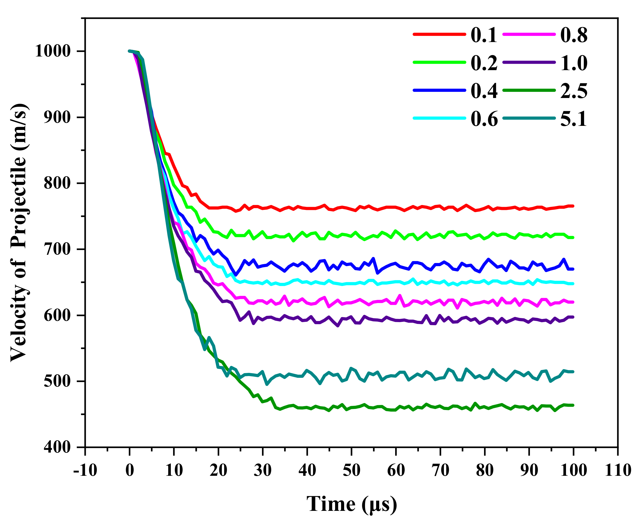
| Item | 1 | 2 | 3 | 4 | 5 | 6 | 7 | 8 | 9 | |
|---|---|---|---|---|---|---|---|---|---|---|
| Ti Thickness (mm) | 0.1 | 0.2 | 0.4 | 0.6 | 0.8 | 1 | 2 | 2.5 | 5.1 | |
| Initial velocity for 400 m/s | Residual velocity (m/s) | −4.65 | −6.64 | −9.21 | −11.3 | −14.4 | −15.3 | −16.3 | −17.2 | −17.1 |
| Results | PP | PP | PP | PP | PP | PP | PP | PP | PP | |
| Initial velocity for 600 m/s | Residual velocity (m/s) | 300 | 150 | 4 | 0 | −3.63 | −2.54 | −1.43 | −5.21 | 0 |
| Results | CP | CP | CP | PP | PP | PP | PP | PP | PP | |
| Initial velocity for 800 m/s | Residual velocity (m/s) | 550 | 503 | 445 | 410 | 358 | 319 | 253 | 150 | 160 |
| Results | CP | CP | CP | CP | CP | CP | CP | CP | CP | |
| Initial velocity for 1000 m/s | Residual velocity (m/s) | 758 | 717 | 669 | 645 | 616 | 580 | 545 | 466 | 514 |
| Results | CP | CP | CP | CP | CP | CP | CP | CP | CP | |
| Material | Ti | Al3Ti | Al |
|---|---|---|---|
| Density [g·cm−3] ) | 4.51 | 3.37 | 2.7 |
| Wave velocity ( | 4.77 | 8.09 | 5.09 |
| Wave impedance | 21.51 | 27.26 | 13.74 |
Disclaimer/Publisher’s Note: The statements, opinions and data contained in all publications are solely those of the individual author(s) and contributor(s) and not of MDPI and/or the editor(s). MDPI and/or the editor(s) disclaim responsibility for any injury to people or property resulting from any ideas, methods, instructions or products referred to in the content. |
© 2025 by the authors. Licensee MDPI, Basel, Switzerland. This article is an open access article distributed under the terms and conditions of the Creative Commons Attribution (CC BY) license (https://creativecommons.org/licenses/by/4.0/).
Share and Cite
Wang, Y.; Yuan, M.; Zhou, P.; Pei, X.; Yang, W.; Tian, Z. Effects of TC4 Thickness on the Penetration Resistance Behavior of Ti-Al3Ti Metal–Intermetallic Laminated Composites. Materials 2025, 18, 1846. https://doi.org/10.3390/ma18081846
Wang Y, Yuan M, Zhou P, Pei X, Yang W, Tian Z. Effects of TC4 Thickness on the Penetration Resistance Behavior of Ti-Al3Ti Metal–Intermetallic Laminated Composites. Materials. 2025; 18(8):1846. https://doi.org/10.3390/ma18081846
Chicago/Turabian StyleWang, Yang, Meini Yuan, Pengfei Zhou, Xin Pei, Wei Yang, and Zehui Tian. 2025. "Effects of TC4 Thickness on the Penetration Resistance Behavior of Ti-Al3Ti Metal–Intermetallic Laminated Composites" Materials 18, no. 8: 1846. https://doi.org/10.3390/ma18081846
APA StyleWang, Y., Yuan, M., Zhou, P., Pei, X., Yang, W., & Tian, Z. (2025). Effects of TC4 Thickness on the Penetration Resistance Behavior of Ti-Al3Ti Metal–Intermetallic Laminated Composites. Materials, 18(8), 1846. https://doi.org/10.3390/ma18081846