
Enhancing the Reliability of Shearing Tools: A Modular Approach with Weld Deposition Technology


Abstract
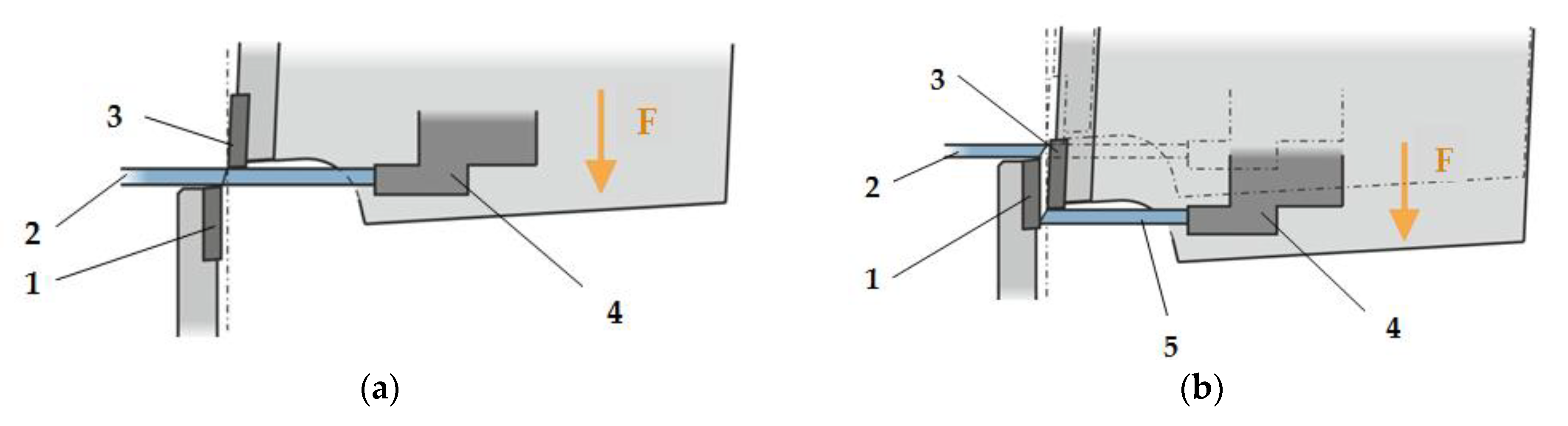
1. Introduction
2. Materials and Methods
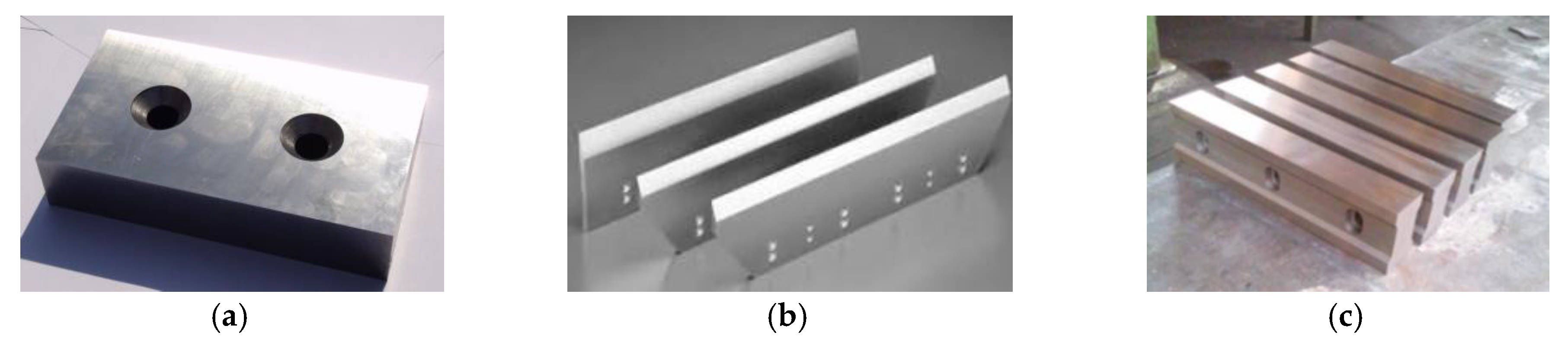
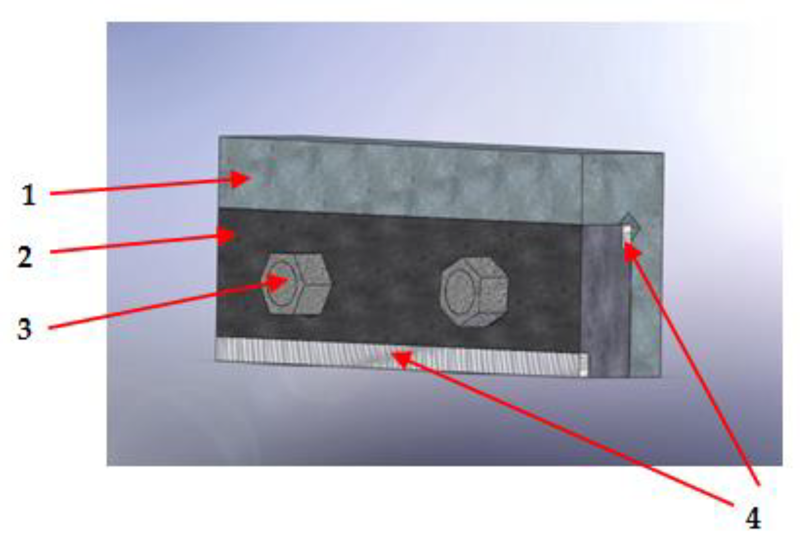
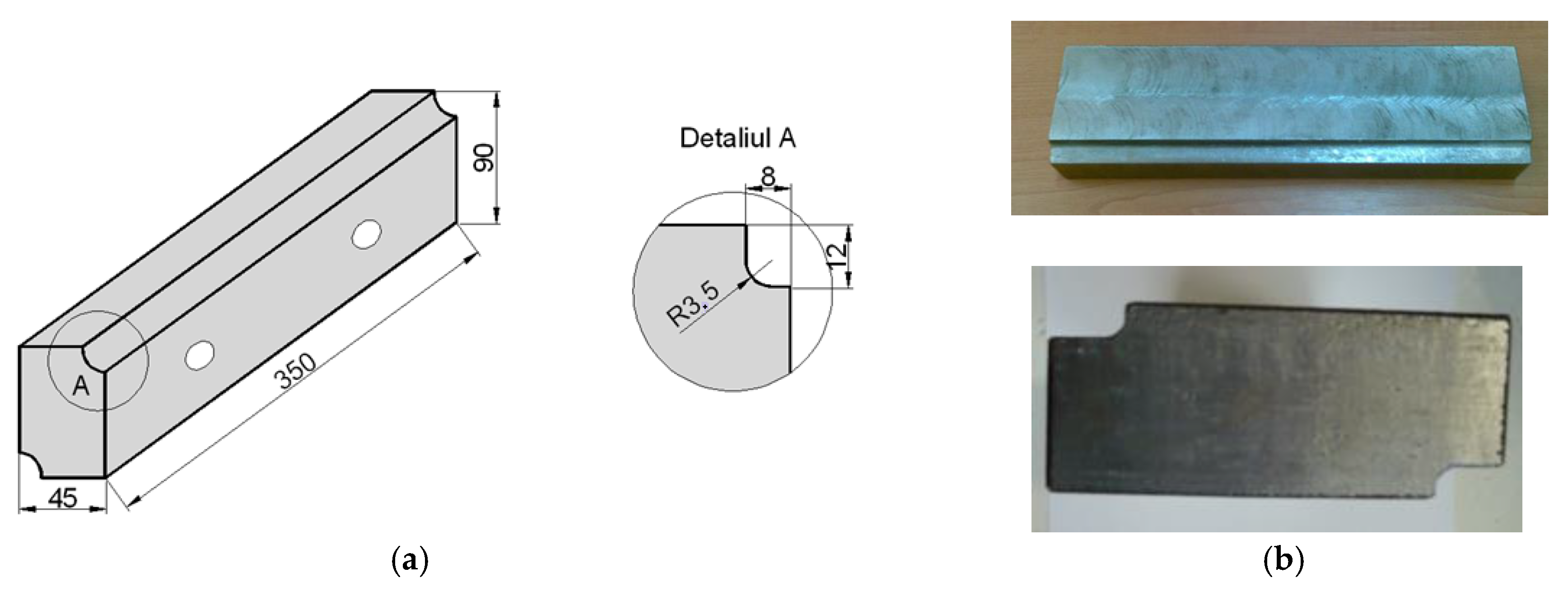
2.1. Manufacturing Shearing Tools from Interchangeable Plates Made by Depositing Cords in Active Areas
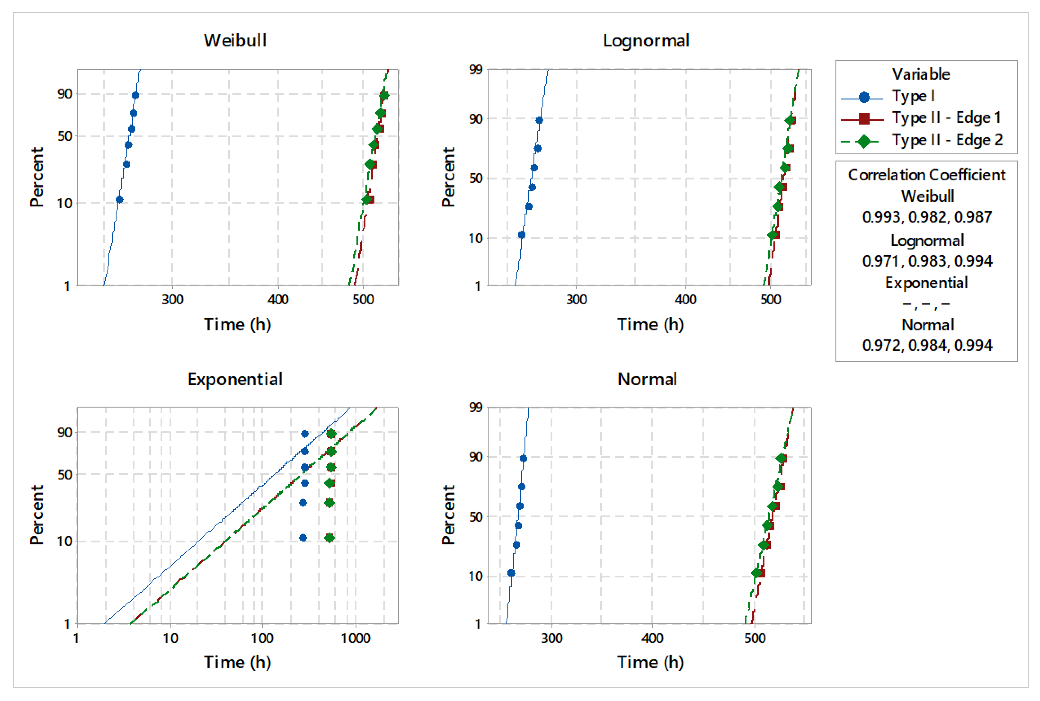
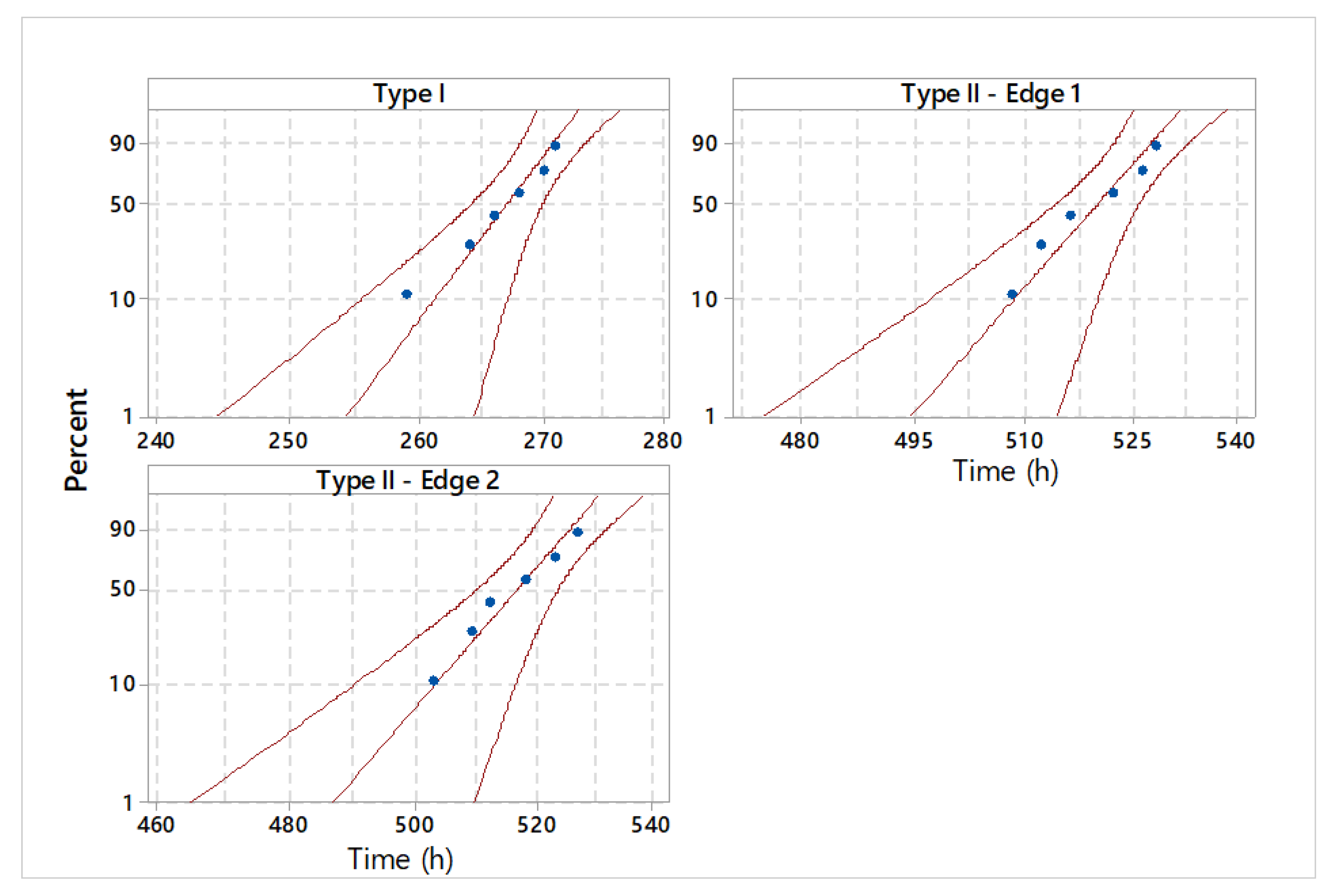
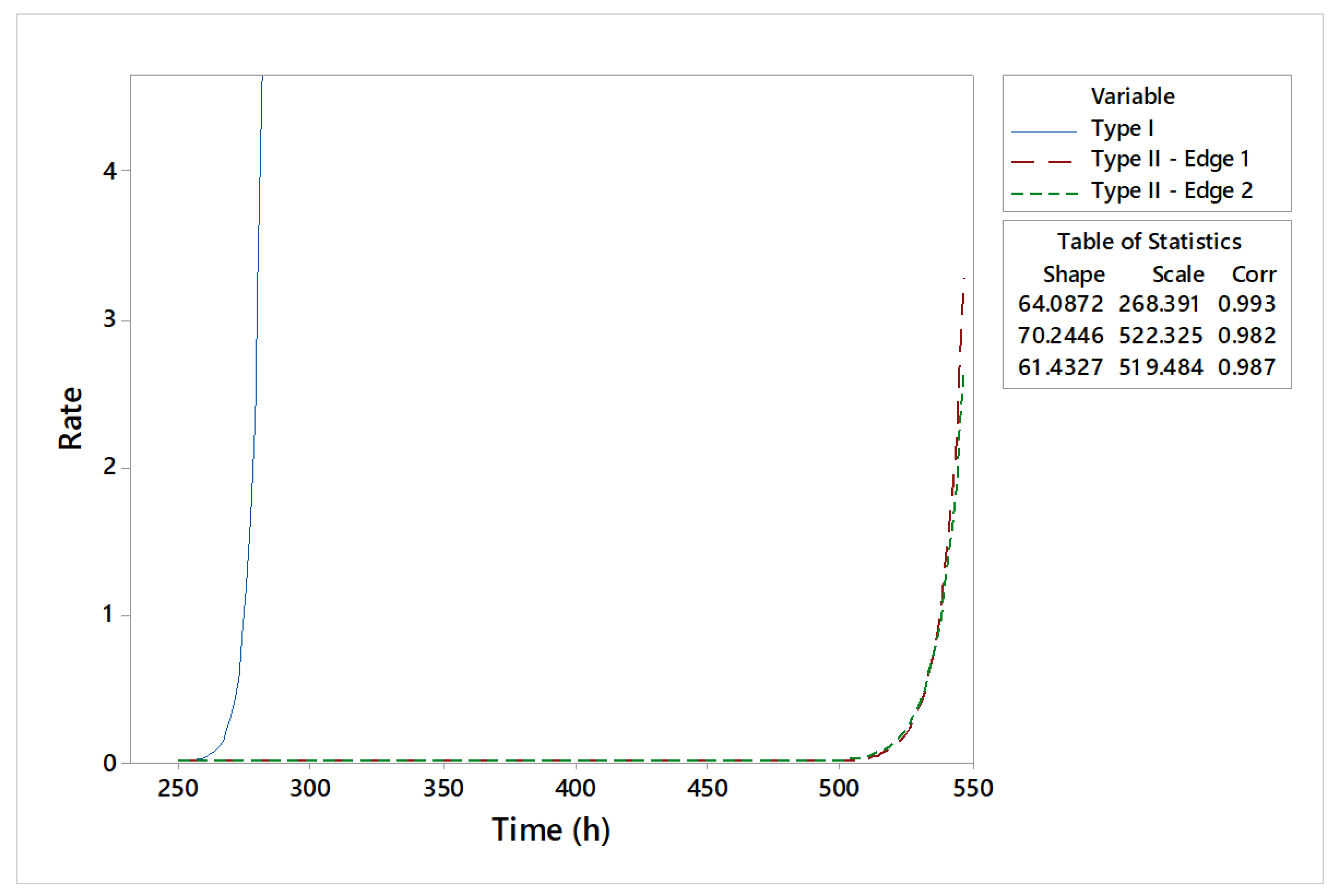
2.2. Lifetime Statistical Analysis of Different Types of Shearing Tools
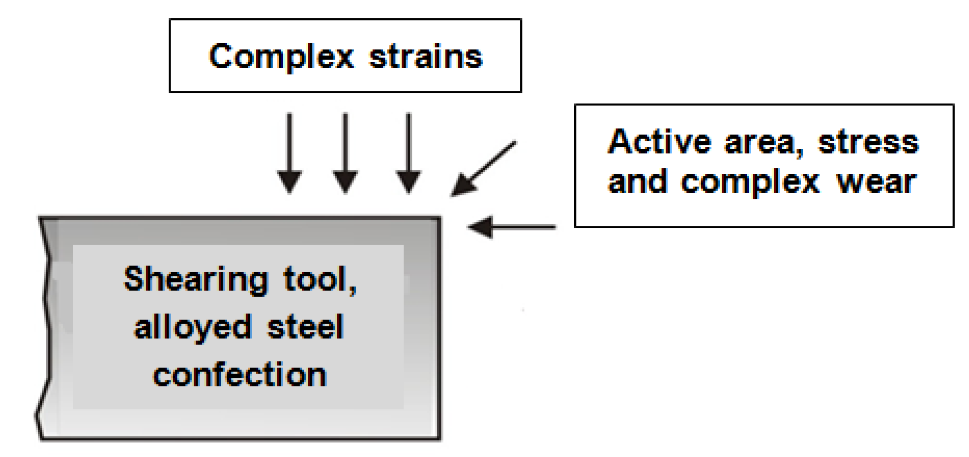
- Type I: shear tool manufactured by a conventional process;
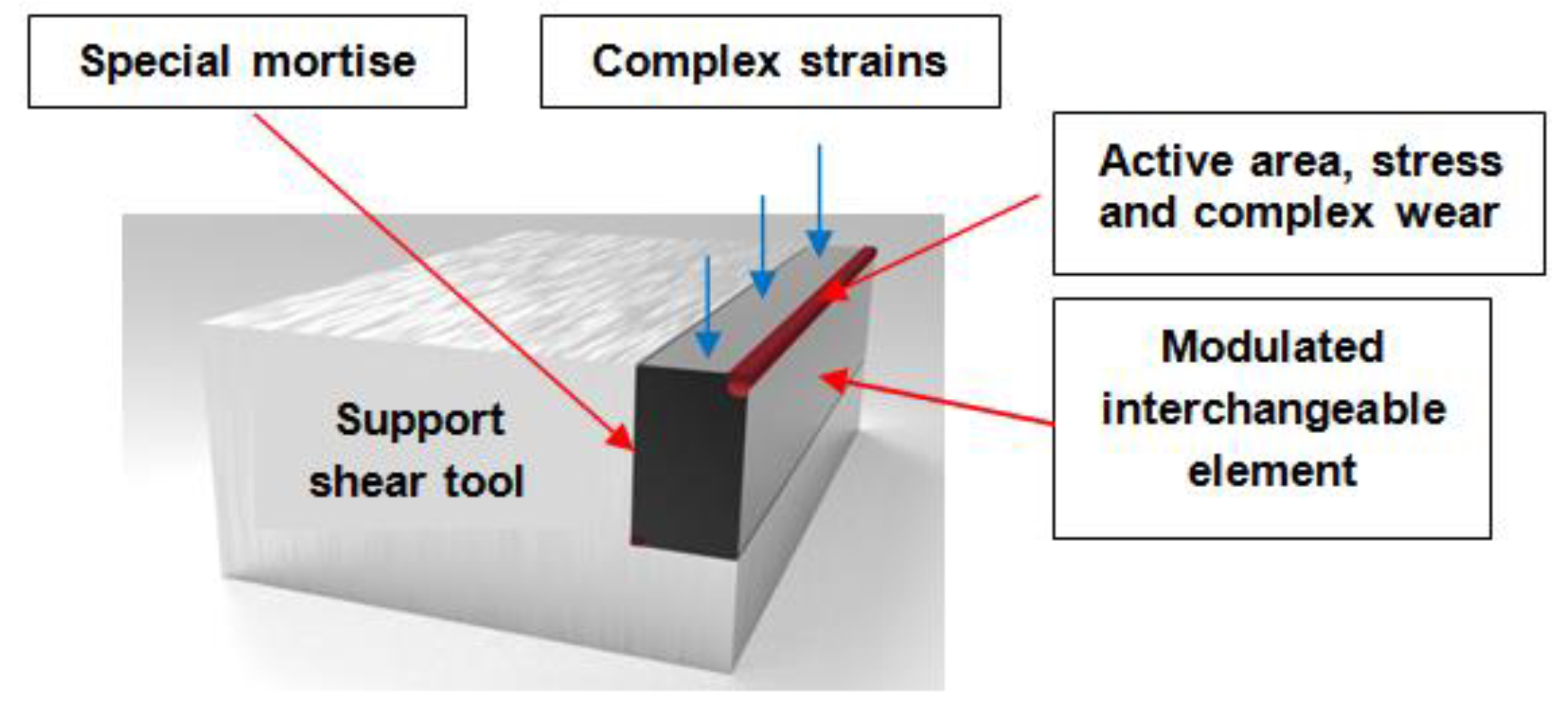
- Type II: shear tool manufactured with interchangeable modular elements loaded by deposition welding with a covered electrode (Figure 8).
3. Results
3.1. Analysis of Interchangeable Modular Elements
- Chemical composition of the deposited metal:
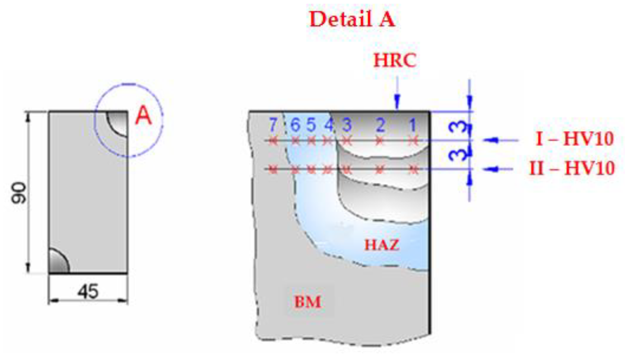
- Macro- and microstructural analyses:
- Hardness measurements:
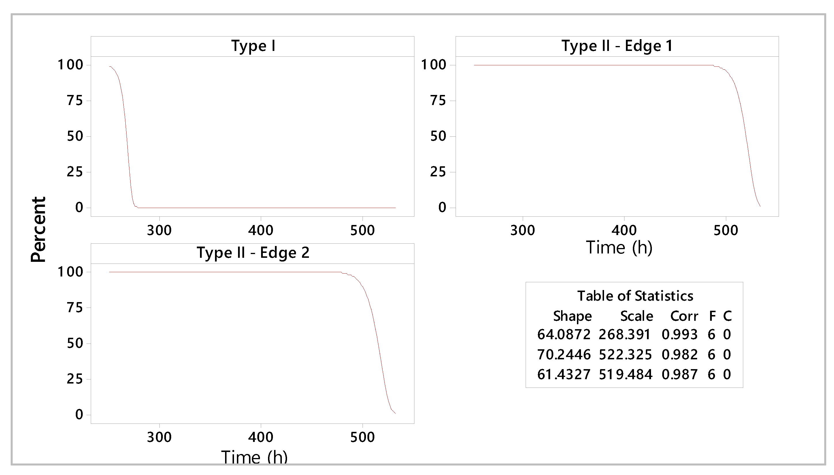
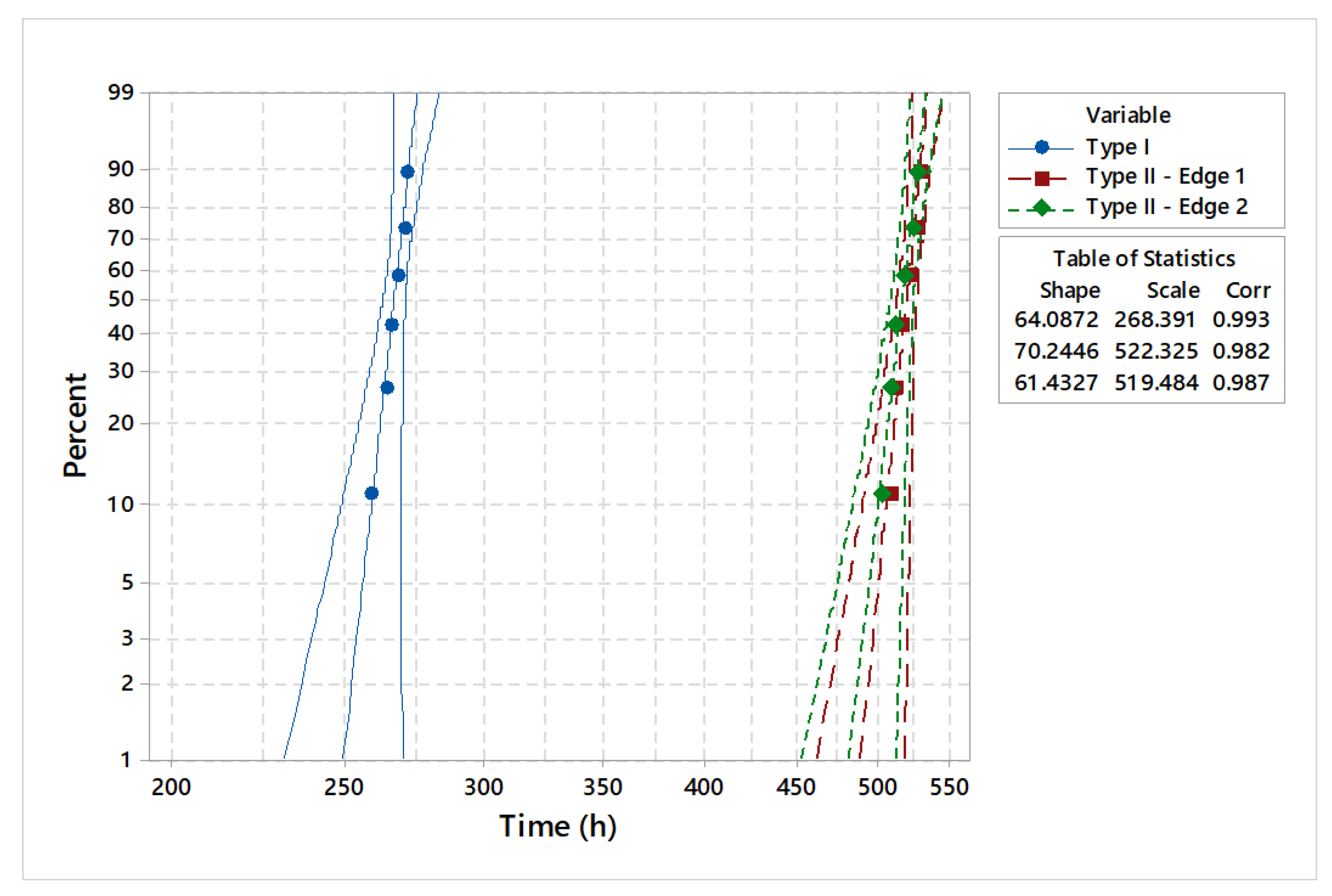
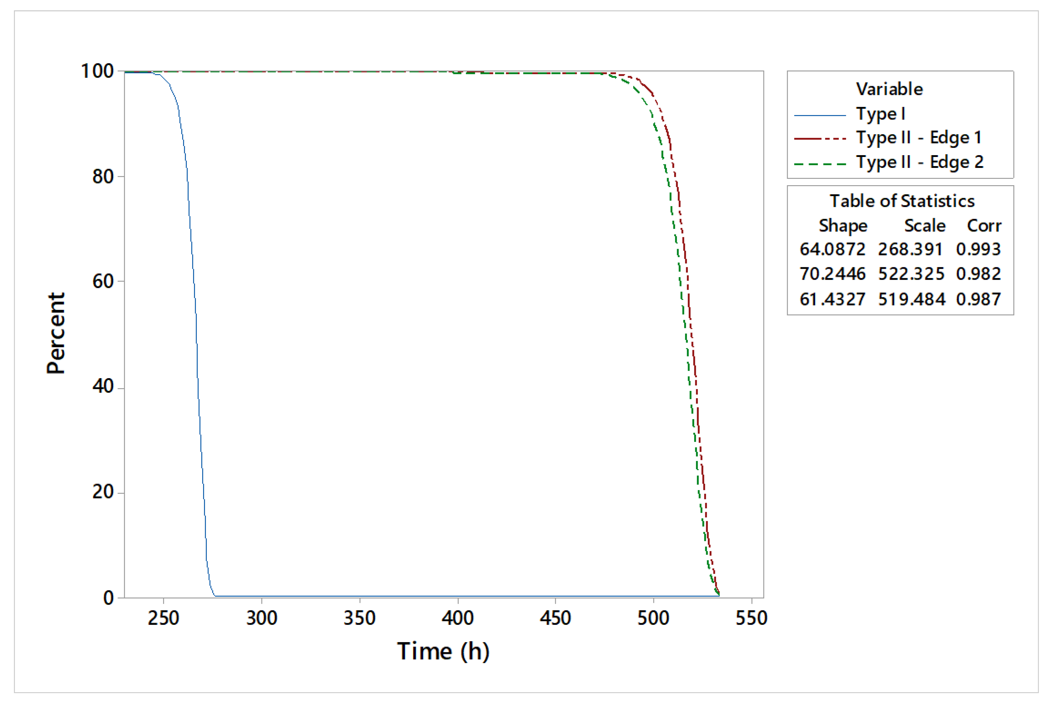
3.2. Comparative Lifetime Analysis of Shearing Tools
4. Discussion
- Use of cheap manufacturing materials.
- Flexible modular interchangeable fixing system.
- High productivity.
- Long operating lifetime, as proven by the study on the reliability estimation of shearing tools, taking into account the two active edges.
- Reduced manufacturing costs due to weld deposition, with loading carried out only in the area of the active edges.
- The process used does not require additional training or qualifications for operators.
5. Conclusions
Author Contributions
Funding
Institutional Review Board Statement
Informed Consent Statement
Data Availability Statement
Acknowledgments
Conflicts of Interest
References
- European Union. Sustainable Development Goals—European Commission. Available online: https://international-partnerships.ec.europa.eu/policies/sustainable-development-goals_en (accessed on 5 February 2024).
- Dubey, A.K.; Yadava, V. Laser beam machining—A review. Int. J. Mach. Tools Manuf. 2008, 48, 609–628. [Google Scholar] [CrossRef]
- Wang, H.; Ma, Y.; Bai, Z.; Liu, J.; Huo, L.; Wang, Q. Experimental investigation and finite element modeling for improved shearing cutting performance using optimized bio-inspired shearing tool. J. Braz. Soc. Mech. Sci. Eng. 2022, 44, 267. [Google Scholar] [CrossRef]
- Colombo, V.; Concetti, A.; Ghedini, E.; Dallavalle, S.; Vancini, M. High-speed imaging in plasma arc cutting: A review and new developments. Plasma Sources Sci. Technol. 2009, 18, 023001. [Google Scholar] [CrossRef]
- Gustafsson, E.; Karlsson, L.; Oldenburg, M. Experimental study of forces and energies during shearing of steel sheet with angled tools. Int. J. Mech. Mater. Eng. 2016, 11, 10. [Google Scholar] [CrossRef]
- Lara de Leon, M.A.; Kolarik, J.; Byrtus, R.; Koziorek, J.; Zmij, P.; Martinek, R. Tool condition monitoring methods applicable in the metalworking process. Arch. Comput. Methods Eng. 2024, 31, 221–242. [Google Scholar] [CrossRef]
- Kolhatkar, A.; Pandey, A. Sheet Metal Shearing Process: An Overview. Trans. Indian Natl. Acad. Eng. 2023, 8, 509–534. [Google Scholar] [CrossRef]
- RAS. Comparison: Swing Beam Shears—Guillotine Shears. Available online: https://www.ras-systems.com/products/cutting/comparison-swing-beam-shears-guillotine-shears (accessed on 4 February 2025).
- Amza, G. Tratat de Tehnologia Materialelor; Romanian Academy Publishing House: Bucuresti, Romania, 2002. [Google Scholar]
- Iovanas, D.M. Researches Regarding the Technology and Reliability of Technological Equipments Reconditioned by Welding. Ph.D. Thesis, Transilvania University of Brasov, Brasov, Romania, 2007. [Google Scholar]
- Binchiciu, H.; Iovanas, R. Loading by Welding with Electric Arc; Technical Publishing House: Bucuresti, Romania, 1992. [Google Scholar]
- Iovanas, D.M.; Dumitrascu, A.E. Lifetime analysis of dies manufactured by conventional processes and reconditioned by deposition welding operation. Materials 2024, 17, 1469. [Google Scholar] [CrossRef] [PubMed]
- Machedon Pisu, T.; Vas, A.; Magyari, M.; Iordache, A. Research on cladding (CMT MIG, WIG ARC mechanized pulse) for molds used for casting. Metal. Int. 2013, 18, 89–94. [Google Scholar]
- Saceanu, C.; Rosu, R.A.; Pascu, D.R. Endurance evaluation of the deposited layers on the coal hammers mills. Metal. Int. 2012, 17, 53–58. [Google Scholar]
- Chivu, O.; Rontescu, C.; Cicic, D.T.; Balan, G. The effects of reconditioning by welding of crankshafts in automotive industry. Metalurgija 2016, 55, 55–58. Available online: https://hrcak.srce.hr/file/209292 (accessed on 25 February 2024).
- Chivu, O.; Cicic, D.T.; Vasile, I.M. The influence of the reconditioning by welding processes on the hardness of crankshafts in the automotive industry. Metalurgija 2016, 55, 281–284. Available online: https://hrcak.srce.hr/file/215835 (accessed on 25 February 2024).
- Shlyarov, V.V.; Komarov, A.A.; Kozyrev, N.A.; Polevoi, E.V.; Mikhno, A.R. Microstructure and Tribological properties of metal layer deposited by arc cladding of powder wire containing titanium powder. Met. Sci. Heat. Treat. 2023, 64, 705–711. [Google Scholar] [CrossRef]
- Szovák, B.; Korsós, K.; Kemény, D.M.; Szalva, P. Effect of the Welding Filler Material on the Mechanical and Corrosive Behavior of Bohler W350 ISOBLOC Hot Forming Tool Steel. Period. Polytech. Mech. Eng. 2023, 67, 137–142. [Google Scholar] [CrossRef]
- Jiang, R. Introduction to Quality and Reliability Engineering; Springer Series in Reliability Engineering; Springer: Berlin/Heidelberg, Germany, 2015. [Google Scholar] [CrossRef]
- Dai, W.; Sun, J.; Chi, Y.; Lu, Z.; Xu, D.; Jiang, N. Review of Machining Equipment Reliability Analysis Methods based on Condition Monitoring Technology. Appl. Sci. 2019, 9, 2786. [Google Scholar] [CrossRef]
- Gourdin, E.; Hansen, P.; Jaumard, B. Finding Maximum Likelihood Estimators for the Three-Parameter Weibull Distribution. J. Glob. Optim. 1994, 5, 373–397. [Google Scholar]
- Hao, M.; Xu, D.; Feng, P. Numerical and experimental investigation of the shear angle in high-speed cutting of Al6061-T6. Int. J. Adv. Manuf. Technol. 2019, 100, 3037–3044. [Google Scholar] [CrossRef]
- Sutter, G. Chip geometries during high-speed machining for orthogonal cutting conditions. Int. J. Mach. Tool. Manuf. 2005, 45, 719–726. [Google Scholar] [CrossRef]
- Tamizharasan, T.; Kumar, N.S. Optimization of cutting insert geometry using Deform-3D: Numerical simulation and experimental validation. Int. J. Simul. Model. 2012, 11, 65–76. [Google Scholar] [CrossRef]


| Electrode Mark | Diameter (mm) | Welding Parameters | |||
|---|---|---|---|---|---|
| Welding Current (A) | Nat. Welding Current | Arc Tension (V) | Welding Speed (m/min) | ||
| EiCr2.5W4.5 V La | 3.25 | 120 ± 10 | CC+ | 20–24 | 0.15–0.2 |
| Distribution | Anderson–Darling (AD*) | Correlation Coefficient |
|---|---|---|
| Weibull | 1.99 | 0.99 |
| Lognormal | 2.07 | 0.97 |
| Exponential | 5.73 | – |
| Normal | 2.06 | 0.97 |
| Distribution | Anderson–Darling (AD*) | Correlation Coefficient |
|---|---|---|
| Weibull | 2.03 | 0.98 |
| Lognormal | 2.02 | 0.98 |
| Exponential | 5.73 | – |
| Normal | 2.02 | 0.98 |
| Distribution | Anderson–Darling (AD*) | Correlation Coefficient |
|---|---|---|
| Weibull | 2.02 | 0.98 |
| Lognormal | 1.98 | 0.99 |
| Exponential | 5.71 | – |
| Normal | 1.98 | 0.99 |
| Distribution | MTTF | ||
|---|---|---|---|
| Type I (h) | Type II—Edge 1 (h) | Type II—Edge 2 (h) | |
| Weibull | 266.03 | 518.13 | 514.73 |
| Lognormal | 266.34 | 518.69 | 515.36 |
| Exponential | 185.21 | 360.62 | 358.91 |
| Normal | 266.33 | 518.66 | 515.33 |
| Shear Tool Type | Parameter | Estimate (h) |
|---|---|---|
| Type I | Shape | 64.08 |
| Scale | 268.39 | |
| Type II—Edge 1 | Shape | 70.24 |
| Scale | 522.32 | |
| Type II—Edge 2 | Shape | 61.43 |
| Scale | 519.48 |
| Parameter | Type I (h) | Type II—Edge 1 (h) | Type II—Edge 2 (h) |
|---|---|---|---|
| Mean (MTTF) | 266.03 | 518.13 | 514.73 |
| Standard deviation | 5.26 | 9.36 | 10.62 |
| Median | 266.86 | 519.60 | 516.39 |
| First quartile (Q1) | 263.22 | 513.14 | 509.05 |
| Third quartile (Q3) | 269.76 | 524.75 | 522.25 |
| Interquartile range (IQR) | 6.53 | 11.61 | 13.19 |
| Chemical Compositions (%) | ||||||||
|---|---|---|---|---|---|---|---|---|
| C | Mn | Si | Cr | Mo | Ni | V | W | Co |
| 0.2–0.5 | - | 1–1.5 | 2–3 | max 1 | max 1.5 | 0.4–1 | 3–5.5 | - |
| Direction/Specific Areas | DM | HAZ | BM | ||||
|---|---|---|---|---|---|---|---|
| 1 | 2 | 3 | 4 | 5 | 6 | 7 | |
| HV 10 Direction I (Weld bead 1) | 736 | 690 | 752 | 252 | 248 | 249 | 192 |
| HV 10 Direction II (Weld bead 2) | 530 | 565 | 572 | 230 | 237 | 228 | 195 |
| Specific Areas | Cords Surface | |||||||||
|---|---|---|---|---|---|---|---|---|---|---|
| 1 | 2 | 3 | 4 | 5 | 6 | 7 | 8 | 9 | 10 | |
| HRC | 53 | 56 | 52 | 54 | 53 | 55 | 56 | 53 | 54 | 52 |
Disclaimer/Publisher’s Note: The statements, opinions and data contained in all publications are solely those of the individual author(s) and contributor(s) and not of MDPI and/or the editor(s). MDPI and/or the editor(s) disclaim responsibility for any injury to people or property resulting from any ideas, methods, instructions or products referred to in the content. |
© 2025 by the authors. Licensee MDPI, Basel, Switzerland. This article is an open access article distributed under the terms and conditions of the Creative Commons Attribution (CC BY) license (https://creativecommons.org/licenses/by/4.0/).
Share and Cite
Iovanas, D.M.; Dumitrascu, A.-E. Enhancing the Reliability of Shearing Tools: A Modular Approach with Weld Deposition Technology. Materials 2025, 18, 1527. https://doi.org/10.3390/ma18071527
Iovanas DM, Dumitrascu A-E. Enhancing the Reliability of Shearing Tools: A Modular Approach with Weld Deposition Technology. Materials. 2025; 18(7):1527. https://doi.org/10.3390/ma18071527
Chicago/Turabian StyleIovanas, Daniela Maria, and Adela-Eliza Dumitrascu. 2025. "Enhancing the Reliability of Shearing Tools: A Modular Approach with Weld Deposition Technology" Materials 18, no. 7: 1527. https://doi.org/10.3390/ma18071527
APA StyleIovanas, D. M., & Dumitrascu, A.-E. (2025). Enhancing the Reliability of Shearing Tools: A Modular Approach with Weld Deposition Technology. Materials, 18(7), 1527. https://doi.org/10.3390/ma18071527