1. Introduction
Buried pipelines are essential for modern energy transmission and municipal infrastructure, serving in the transportation of oil, natural gas, water resources, and urban drainage systems. Their safety and reliability are crucial to a nation’s economic vitality and social stability. However, throughout their service life, these pipelines are often exposed to a range of external impact loads, including earthquakes, construction machinery, traffic, and explosive forces. Such impacts can induce localized or extensive deformation, potentially causing catastrophic failures such as ruptures or leaks, which could lead to significant economic damage and environmental contamination. Therefore, conducting thorough research on the impact response of buried pipelines is critical not only for refining design methodologies but also for enhancing safety assessments and disaster mitigation strategies.
Considerable research has been conducted on the impact response of buried pipelines, primarily focusing on load types, soil–pipeline interaction, and failure mechanisms. Early studies mainly relied on theoretical analysis and simplified models to explore the mechanical behavior of pipelines under impact conditions. Notably, Norman et al. [
1,
2,
3] developed a comprehensive dynamic response theory for pipelines subjected to low-speed impact loads, providing a fundamental theoretical basis for further investigations into pipeline impact responses.
Chen et al. [
4] carried out extensive studies on the behavior of steel pipes with fixed ends under a lateral impact, performing over 130 impact tests to examine the dynamic inelastic behavior of steel pipes with varying diameters, wall thicknesses, and impact locations (midspan, quarter span, and near supports). Their research yielded extensive data on impact velocity, impact force, displacement-time histories, permanent deformation, and various failure modes. Building on this dataset, Shen et al. [
5] proposed a theoretical quasi-static analysis method to predict the response and failure behavior of both pressurized and unpressurized pipelines subjected to lateral impacts. This method incorporated the maximum strain criterion, strain rate effects, and an empirical formula for estimating the plastic hinge length. The theoretical predictions were consistent with experimental results regarding the impact energy threshold and maximum permanent deformation, confirming the applicability of the maximum strain criterion and the empirical hinge length formula in theoretical analyses.
Yang et al. [
6] discovered that the impact location plays a crucial role in determining the damage level to buried pipelines, with midspan impacts causing the most severe damage. O’Rourke et al. [
7] examined the deformation characteristics of buried pipelines subjected to seismic waves, emphasizing that these deformations are primarily influenced by the direction of seismic wave propagation and the soil–pipeline interaction. In a related study, Baker et al. [
8] investigated the local buckling and fracture behavior of pipelines under explosive shock, highlighting the significant role of shock wave intensity and material properties in determining the failure modes.
Mechanical impact loads have also been widely studied. Zhu et al. [
9] employed a nonlinear pipe–soil coupling contact model to analyze the dynamic response of buried pipelines under landslide-induced impact loads. Their study explored the effects of the rockfall impact velocity, pipeline burial depth, diameter-to-thickness ratio, and soil type on axial compressive strain. The results indicated that ellipsoidal rockfalls generate considerably higher impact forces compared to spherical counterparts of the same volume, with larger rock masses further amplifying the impact intensity. Trautmann et al. [
10] conducted experimental investigations into the effects of varying soil properties on pipeline deformation, emphasizing the influence of soil stiffness and damping characteristics on the pipeline’s impact response. Zhang et al. [
11] performed a comprehensive analysis of the deformation, stress, and strain of buried steel pipes subjected to impacts from hazardous rocks using finite element simulations. Their findings revealed that the pipeline’s cross-section undergoes significant deformation during the impact process, transforming from elliptical to peach-shaped and eventually to crescent- or hourglass-shaped. The study also systematically analyzed the buckling behavior of pipelines under both lateral and longitudinal inclined impacts.
In recent years, Choudhury et al. [
12] have focused on the effects of seismic landslides and other ground deformation modes on buried pipelines, as well as the impact of ground vibrations from pipeline ruptures on surrounding pipelines. Lee [
13] studied the seismic performance of buried natural gas pipelines under earthquake loading, revealing that strain responses at the pipeline ends are highly influenced by soil and boundary conditions. Notably, under soft clay soil conditions, the strain at the pipeline ends can reach up to 70% of the allowable limit. Arabzadeh [
14] investigated the impact of burial depth on the deformation of subsea pipelines, concluding that increased burial depth results in both higher maximum impact loads and greater indentation depths. Dou [
15] explored the effects of internal pressure on a pipeline’s resistance to impacts, finding that higher internal pressure leads to increased maximum impact forces, reduced lateral displacements, and lower absorbed impact energy.
Despite there having been significant progress in studying the impact response of buried pipelines, such as Alsos H.S.’s [
16] research on the effects of impacts on buried pipelines, which concluded that pipeline deformation under external impacts was primarily influenced by the mass and velocity of the impacting object rather than its kinetic energy, several limitations persist in current studies. First, existing research tends to focus on individual influencing factors and lacks multi-factor coupling analysis, particularly regarding the impact response of pipelines at varying burial depths. However, in practical engineering applications, pipelines are often subjected to multiple factors simultaneously. Second, current experimental methods face challenges in load application and data processing. For example, assessing the complex interactions between the soil layer and the pipeline during loading is difficult, and measuring changes in the internal pressure of pressurized pipelines presents additional challenges. These limitations hinder our understanding of pipeline impact response characteristics under real-world conditions. Therefore, further systematic research is urgently needed to uncover the multi-factor response mechanisms of buried pipelines under impact loads.
In this study, we aimed to investigate the deformation response mechanisms of buried pipelines under impact loads through experimental methods, focusing on key influencing factors such as the soil environment, burial depth, and internal pressure levels. The findings provide a scientific basis for safe design and disaster prevention in pipelines. The specific research objectives included: (1) conducting experimental studies to characterize the deformation of buried pipelines under various impact loads, thereby elucidating the role of pipeline–soil interaction in impact response; (2) analyzing the influence of soil properties, burial depth, and internal pressure levels on the impact response of pipelines based on experimental data; and (3) developing a theoretical model for the impact response of buried pipelines to support the safety assessment of pipelines based on the experimental results.
To achieve these objectives, for the present study, we designed and established an experimental setup, described in
Section 2, to examine the impact response of buried pipelines, conducting impact tests with varying soil environments, burial depths, and internal pressure levels.
Section 3 presents a comprehensive analysis of the data collected under typical operating conditions. Finally, the mechanisms of key influencing factors, including the soil environment, burial depth, and internal pressure levels, are discussed in conjunction with the experimental results.
2. Experiment Design and Apparatus
2.1. Test Specimens and Experimental Apparatus
This experiment employed thin-walled seamless circular pipes fabricated from API 5L X100 pipeline steel as test specimens, with a nominal wall thickness of 1 mm and a diameter-to-thickness ratio D/t = 25. The material conforms to the API 5L specifications for grade X100. Uniaxial tensile tests measured the yield stress, elastic modulus, and elongation at fracture of the experimental X100 steel batch as 763 MPa, 209 GPa, and 13.6%, respectively. The specimen dimensions include an overall length of 780 mm, span of 330 mm, and outer diameter of 25 mm. It should be emphasized that the findings of this study are strictly applicable to thin-walled pipe configurations.
Impact loading was applied using a drop-weight testing apparatus (shown in
Figure 1a), with the specimen positioned directly beneath the drop weight at mid-span. The specimen was secured in place by an L-shaped base and cover plate, which featured circular openings that matched the pipe’s outer diameter. The cover plate compressed the specimen against the L-shaped base using high-strength bolts, effectively restricting both radial and axial deformations during the test, thus establishing fixed boundary conditions at both ends of the pipe.
To improve the testing efficiency and eliminate residual welding stresses, pressure transmission and sealing were achieved using an adapter and clamps, as shown in
Figure 1c. In this connection assembly, the male sleeve passes through the end of the pipe and locks the clamp by compressing the clamp and female sleeve together, applying radial pressure to secure the pipe’s end. The other end of the coupling is connected to a valve via an adapter, enabling the pressurization of the pipeline’s interior. At the opposite end of the pipe, the valve is replaced with a pressure transmitter, which monitors and records the internal pressure in real time.
To evaluate the interdependent influences of the soil type, burial depth, and internal pressure on pipeline impact behavior, a standardized experimental protocol was implemented with a fixed energy input across all test conditions. A 36.2 kg drop-weight apparatus with a 25 mm diameter hemispherical drop hammer served as the controlled energy source. The impact energy of 266 J was systematically achieved by releasing the mass from a calibrated 750 mm elevation, calculated through fundamental gravitational potential energy principles. This methodology maintained consistent kinetic energy transfer to test specimens while varying environmental parameters, enabling the direct comparison of soil–pipeline interaction mechanisms under equivalent mechanical loading conditions.
The present study focused on the dynamic response of pipelines in buried environments; thus, a specialized burial fixation device was designed (shown in
Figure 1b). This apparatus consists of two soil-retaining steel plates, each 600 mm in length and 5 mm in thickness, arranged axially along the pipeline. The plates are securely attached to the base of the drop weight using bolts to ensure a sufficient soil burial environment for the test.
2.2. Buried Environments
To examine the response characteristics of pipelines buried in different soil types, typical soils such as soft clay, sand, and loess were selected for the present impact tests. Before conducting the impact tests, material tests were performed on the three selected soil types to determine their basic mechanical parameters, as detailed in
Table 1. Additionally, a series of tests were conducted on suspended pipelines as a control for burial effects. To evaluate the coupling influence of soil and internal pressure, in addition to conducting tests on empty pipelines, a series of tests was also performed on pipelines pressurized to 10 MPa using the device shown in
Figure 1a.
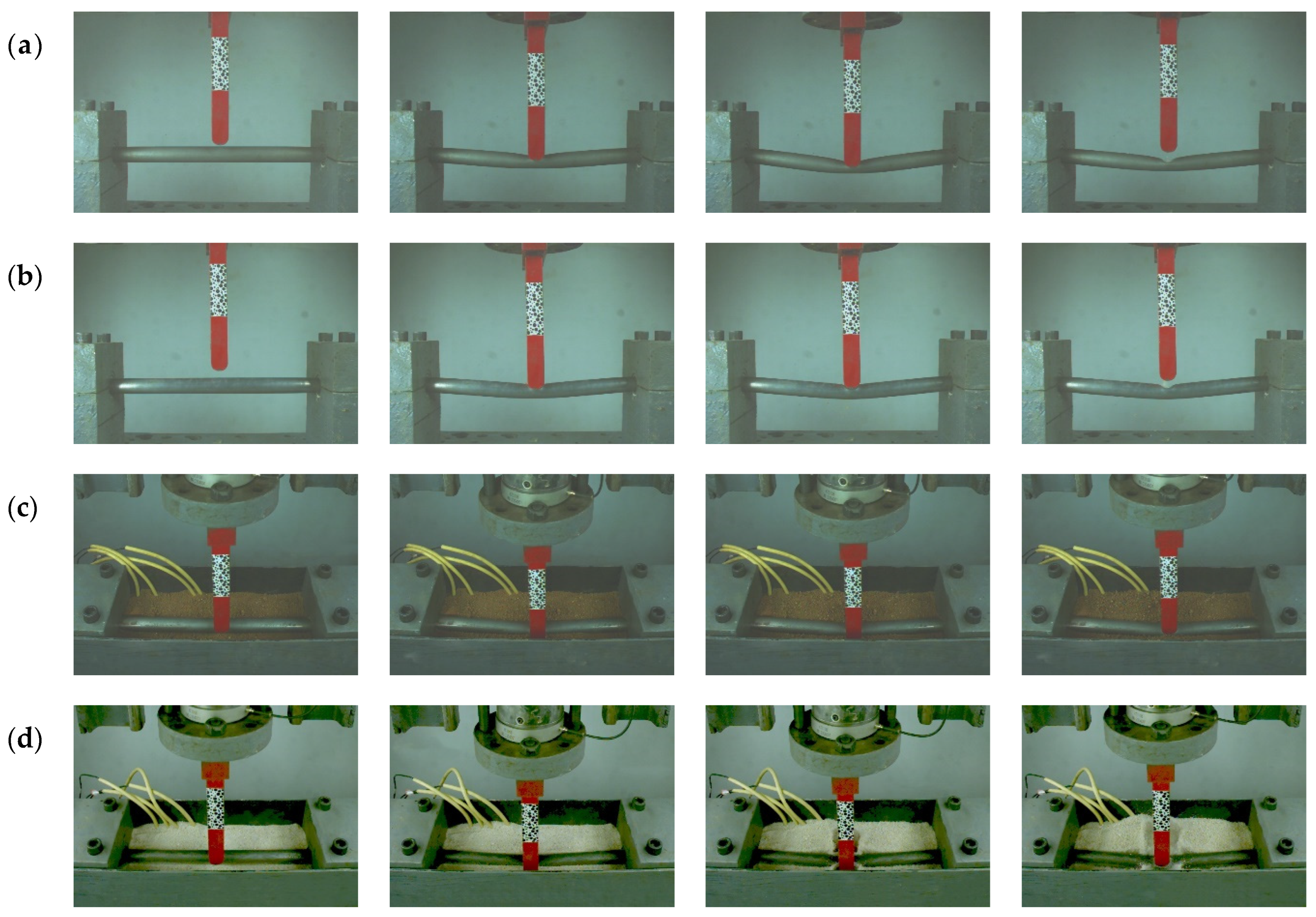
During the experiments, the burial depth of the pipeline was controlled by adjusting the soil fill depth. To investigate the influence of burial depth on the pipeline’s response, three burial configurations were tested, as shown in
Figure 1e. For clarity and ease of comparison, these configurations are referred to as “0D”, “1D”, and “2D”, representing the pipeline located at the soil surface, buried at a one-diameter depth, and buried at a two-diameter depth, respectively.
2.3. Measurements and Test Procedures
During the experiments, the impact force and internal pressure variations were measured using the load cell, pressure sensors, and dynamic acquisition system shown in
Figure 1a. Based on these measurements, digital image correlation (DIC) technology was used to track the digital speckle on the surface of the drop weight, allowing for precise displacement measurements. These data were synchronized with the timestamps from the data collected by the load sensor to derive relationships between impact loads, internal pressures, and vertical displacements covering the whole response of the pipeline.
To capture changes in soil pressure during the impact process, as shown in
Figure 1d, four pressure sensors were embedded in the soil. These sensors were positioned at distances of 30 mm and 60 mm from the bottom of the pipeline. Specifically, Sensor ① was placed directly beneath the left side of the pipeline near its end, Sensor ② was positioned at a quarter span directly below the pipeline, and Sensors ③ and ④ were placed directly beneath the midpoint (impact location) of the pipeline.
The following is a brief description of the experimental procedure. The connecting sleeves at both ends of the pipeline specimens were attached to the corresponding connectors. For the pressurized pipeline, the quick connector on the pressure sensor side was released. Water was then injected into the pipeline through the pressurization apparatus until a stable flow emerged from the quick connector outlet, ensuring that the pipeline was completely filled with water and free from residual air. The pipeline specimens were fixed as described earlier, and the internal pressure reached the predetermined level. The soil was layered and compacted to the required depth in the burial area, with each layer being 30 mm thick. Simultaneously, the pressure sensors were buried at their designated depths.
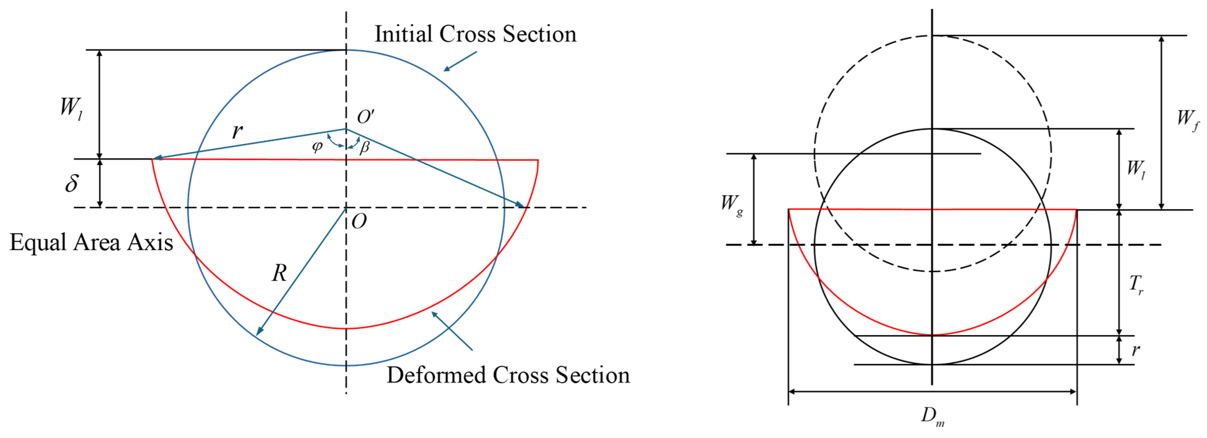
After raising the drop weight to the specified height, all sensor readings were calibrated, and the drop weight was released to impact the pipeline specimen. A high-speed camera recorded the deformation process of both the pipeline and the surrounding soil. The internal pressure sensors monitored changes in the internal pipe pressure, while the soil pressure sensors collected data on variations in the soil layer pressure during the impact process. At the end of the experiment, before the specimen was removed from the self-restraint device, a vernier caliper was used to measure the vertical deflection, lateral width, and remaining thickness of the impacted area of the pipeline.
2.4. Loading Conditions
The experiments were organized into four groups, i.e., unburied, soft clay, sand, and loess groups. In the unburied group, two sets of tests were performed: one on an empty pipeline and another on a pipeline filled with water at 10 MPa. The remaining three groups underwent crossover testing for various burial depths and internal pressure conditions. Each configuration was repeated three times, and the average data were taken as the final results for that condition. This systematic experimental design facilitates our understanding of the mechanisms by which different factors influence the dynamic impact response of pipelines. All the loading conditions in the present study are summarized in
Table 2.
4. Conclusions and Outlook
In this study, we conducted experimental research to analyze the influence of the internal pressure, soil type, and burial depth on the impact response of pipelines. The following main conclusions can be drawn:
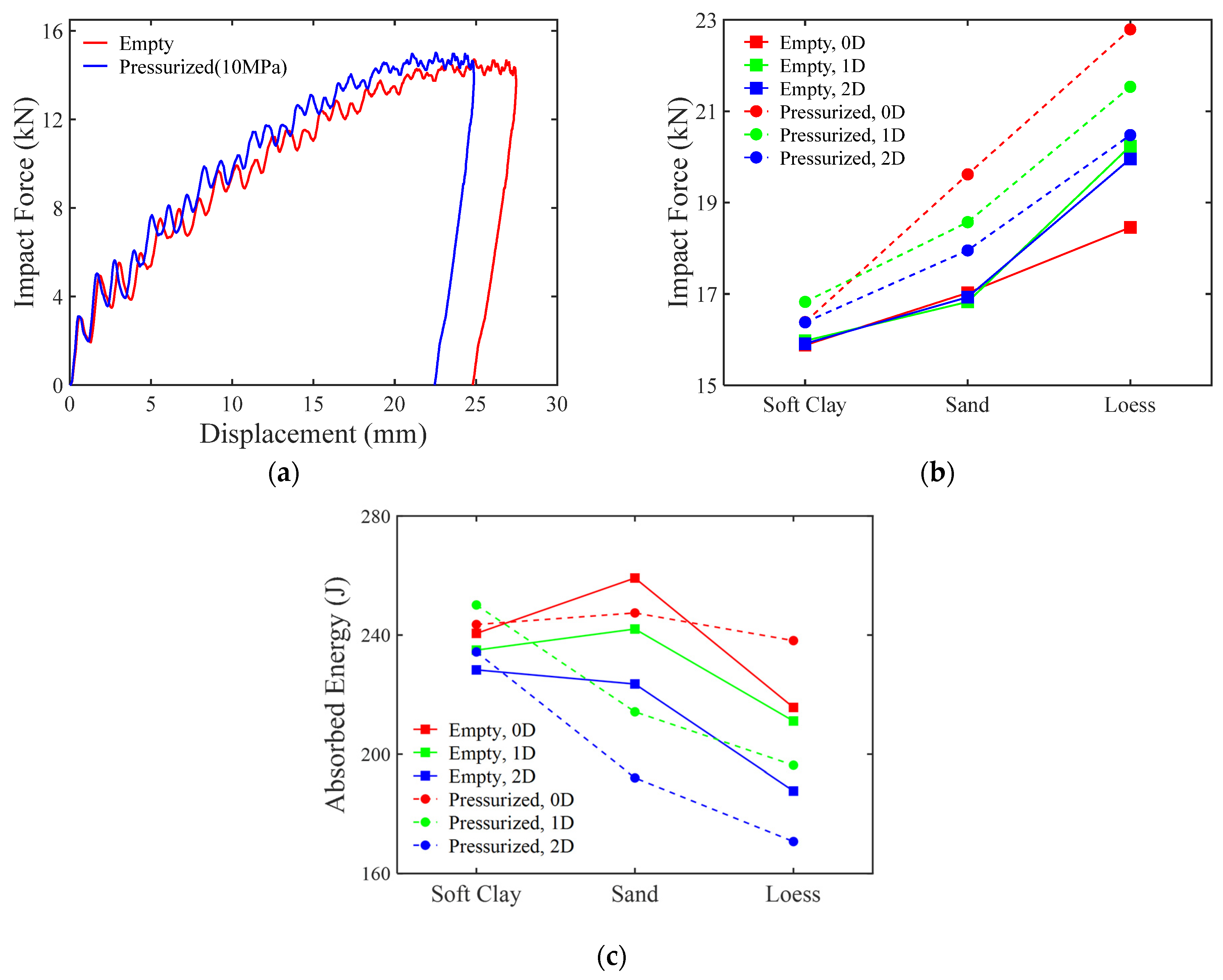
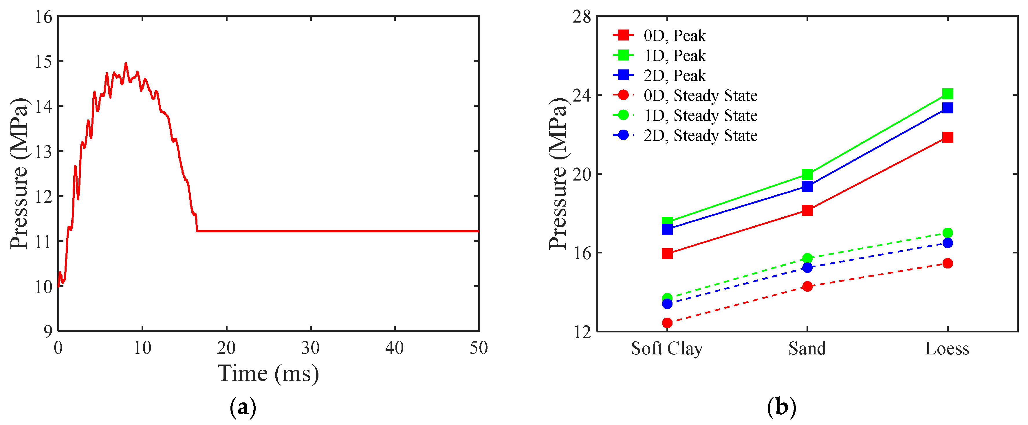
(1) The peak impact force of a pipeline with internal pressure is significantly higher than that under conditions without internal pressure. Liquid-filled pipelines are highly sensitive to changes in internal volume; even slight fluctuations can lead to substantial pressure variations, altering the whole response characteristics of the pipeline due to changes in the distribution of circumferential stress.
(2) As soil hardness increases, the peak impact force on the pipeline also rises, particularly in loess environments, where changes in the internal pressure of pressurized pipelines are especially pronounced. This indicates that higher soil hardness enhances the constraining capacity during the deformation process of the pipeline, resulting in elevated levels of internal pressure.
(3) An increase in burial depth does not always lead to a reduction in impact force. In hard soil environments, increasing the burial depth may enhance the load transfer performance of the overlying soil, thereby increasing the impact force. For empty pipelines, there is no evident negative correlation between the burial depth and peak impact force; however, an appropriate burial depth can optimize the dynamic response of pipelines under external impacts.
Future work could adopt a combined approach, with numerical simulation and experiments, to systematically analyze the roles of various variables. This will contribute to a better understanding of pipeline responses under complex loading conditions.


