Article

Analysis of a Two-Stage Magnetic Precession Gear Exploiting 3D Finite Element Method

1
Faculty of Mechanical Engineering, Poznan University of Technology, pl. Marii Sklodowskiej-Curie 5, 60-965 Poznan, Poland
2
Faculty of Control, Robotics and Electrical Engineering, Poznan University of Technology, pl. Marii Sklodowskiej-Curie 5, 60-965 Poznan, Poland
*
Author to whom correspondence should be addressed.
Materials 2025, 18(23), 5277; https://doi.org/10.3390/ma18235277 (registering DOI)
Submission received: 22 October 2025 / Revised: 17 November 2025 / Accepted: 19 November 2025 / Published: 22 November 2025
(This article belongs to the Section Materials Simulation and Design)

Abstract

The paper presents the results of numerical simulations carried out to investigate the influence of selected geometric parameter–precession angle and dimensions of the magnetic circuit of a two-stage magnetic precession gear on the magnetic torques acting on its active components. The operating principle of the proposed gear and the developed numerical model based on the 3D finite element method (FEM) are discussed. The study focuses on the effects of air gap length, magnet dimensions, pole pitch coverage and precession angle. The results confirm a strong correlation between these parameters and the transmitted torque, providing valuable guidelines for the optimal design of high-torque, compact and efficient magnetic precession gears.

Graphical Abstract

1. Introduction

Magnetic gears (MGs) offer several advantages over traditional mechanical gears, including reduced maintenance, high reliability, and inherent overload protection due to their contactless operation. These benefits make MGs particularly suitable for applications requiring low maintenance, such as marine propulsion and wind power generation [1,2,3]. One of the primary types of MGs is the coaxial magnetic gear (CMG), which is known for its high torque transmission capability [4,5]. Another innovative approach involves integrating magnetic gears into the structure of permanent magnet synchronous machines, creating a more compact and efficient drive unit. This integration can lead to additional mass savings and improved performance in applications requiring high torque density [1]. Magnetic gears also offer advantages in terms of noise and vibration reduction as well as reliability improvement. Unlike mechanical gears, MGs do not require lubrication and are less prone to wear and tear, making them ideal for applications where maintenance is challenging or costly [6,7].
However, magnetic gears face issues such as severe eddy current and hysteresis losses in the magnetic circuit and centrifugal forces at high speeds, which can lead to efficiency drops and potential damage [4]. Magnetic gears also have a much lower torsional stiffness than mechanical gears. This low stiffness results in long-lasting oscillations during transient changes in speed and load [8,9,10,11]. The torsional stiffness of magnetic gears is significantly lower than the meshing stiffness of mechanical gears, which affects their dynamic performance [12,13].
The article is focused on analysis of magnetic precession gears (MPG), which offer several advantages over traditional mechanical gearboxes and other types of MGs, primarily due to their unique design and operational principles that leverage magnetic forces for torque transmission. One of the key benefits is their ability to achieve greater transmission ratios compared to other magnetic gears, thanks to their specific geometrical and kinematical design, which allows for optimal gear ratio configurations [14]. The transmission ratio for this type of gear may be obtained in the range of 1/80 ÷ 1/10,000 [15]. Thanks to these advantages, magnetic precession gear could be applied, for example, in tidal and wave energy converters, low-speed direct-drive wind turbines, hermetic pumps for corrosive or radioactive fluids, bioreactors and pharmaceutical mixers, and precision positioning systems in space and underwater robotics. Figure 1 presents the CAD model and the kinematic diagram of the MPG.

2. Materials and Methods

The research conducted aims to understand the effect of geometric parameters and the dimensions of the magnetic circuit on the magnetic torques acting between the magnetically active components of the MPG. The transmitted torque constitutes a fundamental performance parameter of an MG. Therefore, the design process of the newly proposed gearbox required the development of a reliable model capable of accurately determining torque values for specific geometric and magnetic configurations. In magnetic gears, torque transmission is governed by the distribution of the magnetic field within the air gaps separating the magnetically active components of the MPG. To investigate this phenomenon, a comprehensive analysis of the magnetic precession gear performance was conducted using a finite element model of the magnetic field, implemented in the Ansys Maxwell 3D professional FEM environment.
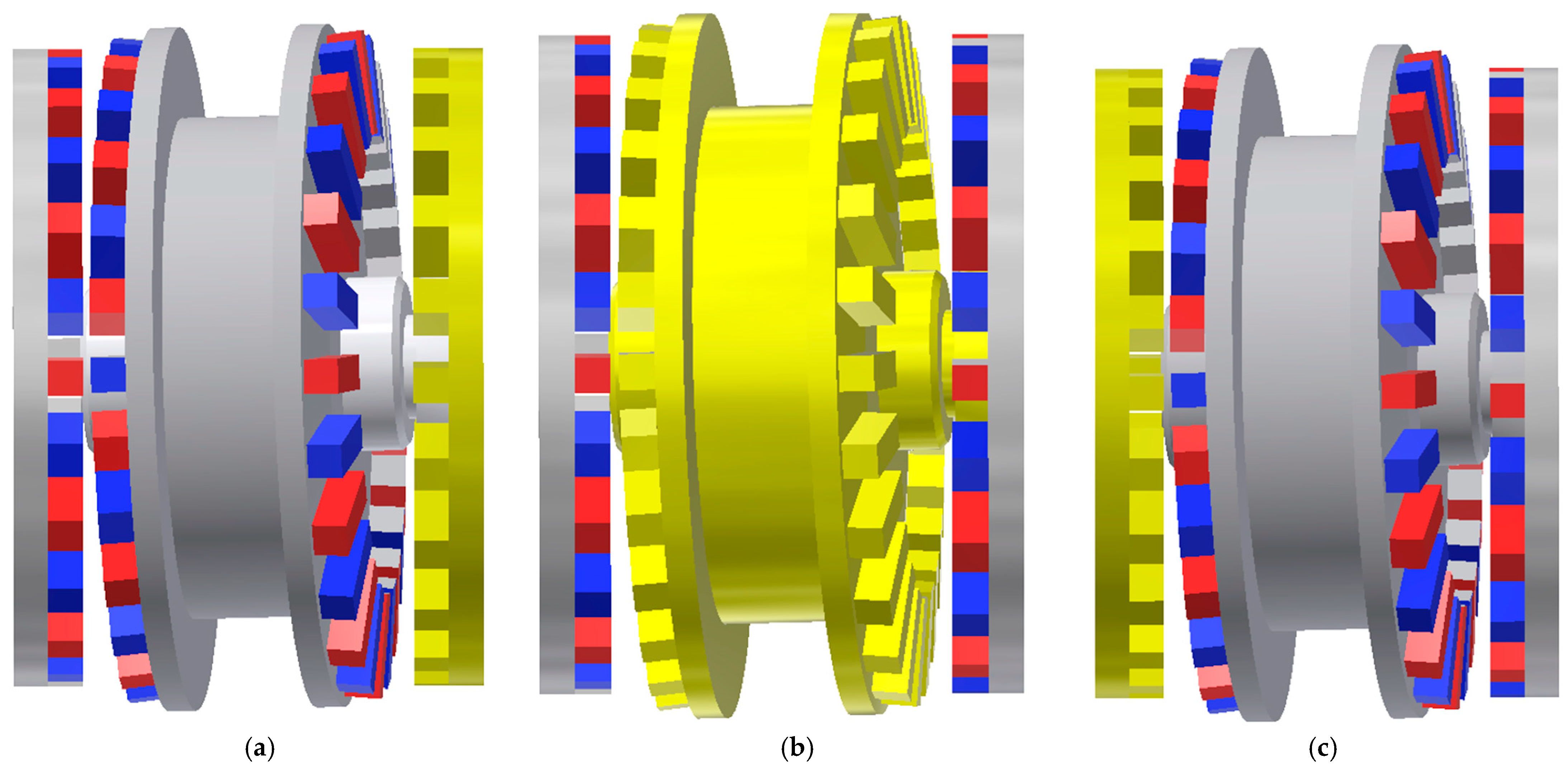
The examined system incorporates two air gaps that directly participate in torque transmission. Owing to the presence of non-coaxial rotational axes, torque evaluation was conducted for three different geometrical arrangements, as presented in Figure 2.
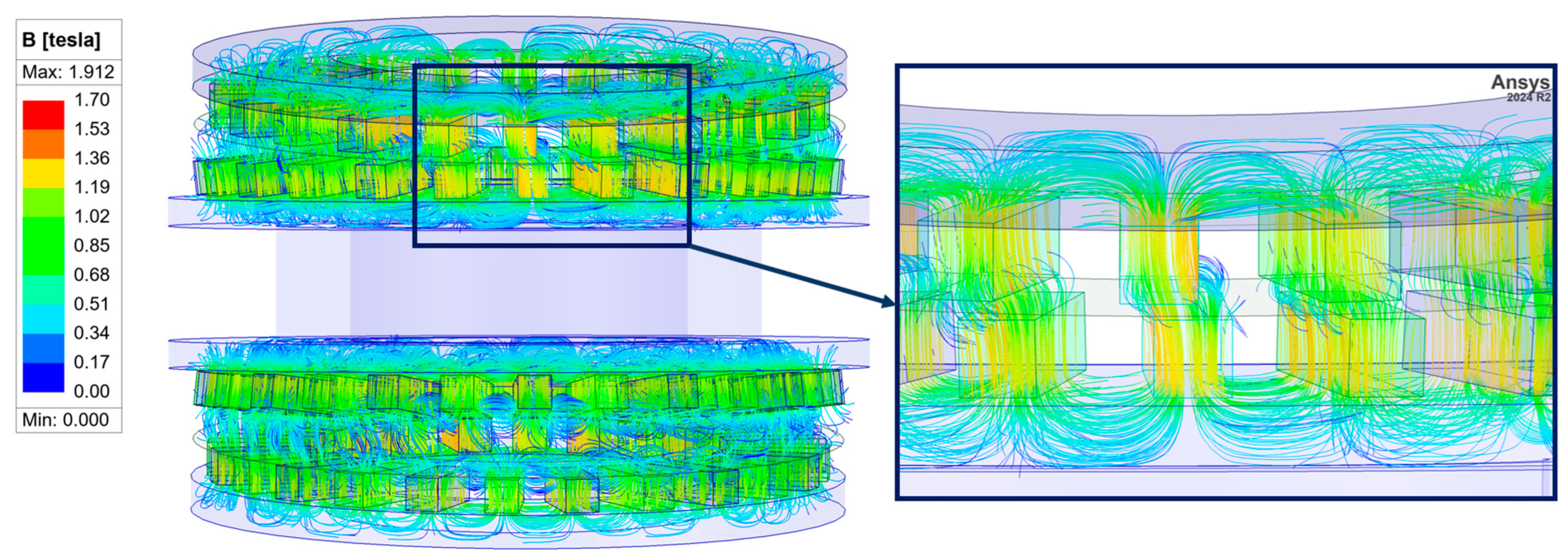
For the determination of torque acting between the interacting elements of the designed gear, the Maxwell stress tensor method was employed [16]. The finite element mesh comprised approximately 897,000 tetrahedral elements, with nonlinear magnetic properties of the core material duly accounted for. At the present stage of the study, the effects of eddy currents have been disregarded. An example of the magnetic flux distribution within the air gap between the immovable outer ring and the intermediate ring is illustrated in Figure 3. Detailed description of the developed numerical model of the MPG can be found in [17]. Accuracy of the model was verified experimentally on the prototype of the gear ratio 144 and precession angle 6°. For all analyzed cases, root mean square error does not exceed 10% of the maximum transmitted torque which is considered a good agreement between model and experiment.
As highlighted in the introduction, a characteristic property of magnetic gears is their significantly lower stiffness relative to conventional mechanical gears. Consequently, variations in load torque lead to changes in the mechanical angle between the movable components, as illustrated in Figure 4. This behavior is analogous to the correlation between load torque and the internal load angle observed in synchronous motors [18,19]. The blue arrows in Figure 4 represent both the magnitude and direction of the applied load torque.
Two load angles can be defined for the studied MPG. The load angle between the immovable ring and the intermediate ring will be marked as β1 while the load angle between the intermediate ring and the output ring will be depicted as β2.
The next chapter presents the results of FEM simulations aimed at examining the influence of selected geometric parameter–precession angle and dimensions of the magnetic circuit on the magnetic torques acting on the magnetically active components of the MPG, namely the output ring (Tout), the immovable ring (Tbase), and the input shaft together with the intermediate ring (Tin). The developed numerical model of the magnetic field in the studied gear enables an independent evaluation of the effect of each parameter. Section 3.1 addresses the impact of air gap lengths. The investigations reported in Section 3.2 and Section 3.3 focus on the influence of the dimensions and shape of the magnets. Finally, the results presented in Section 3.4 allow for an assessment of the effect of the precession angle.

3. Results and Discussion

3.1. Examination of the Influence of Air Gap Lengths

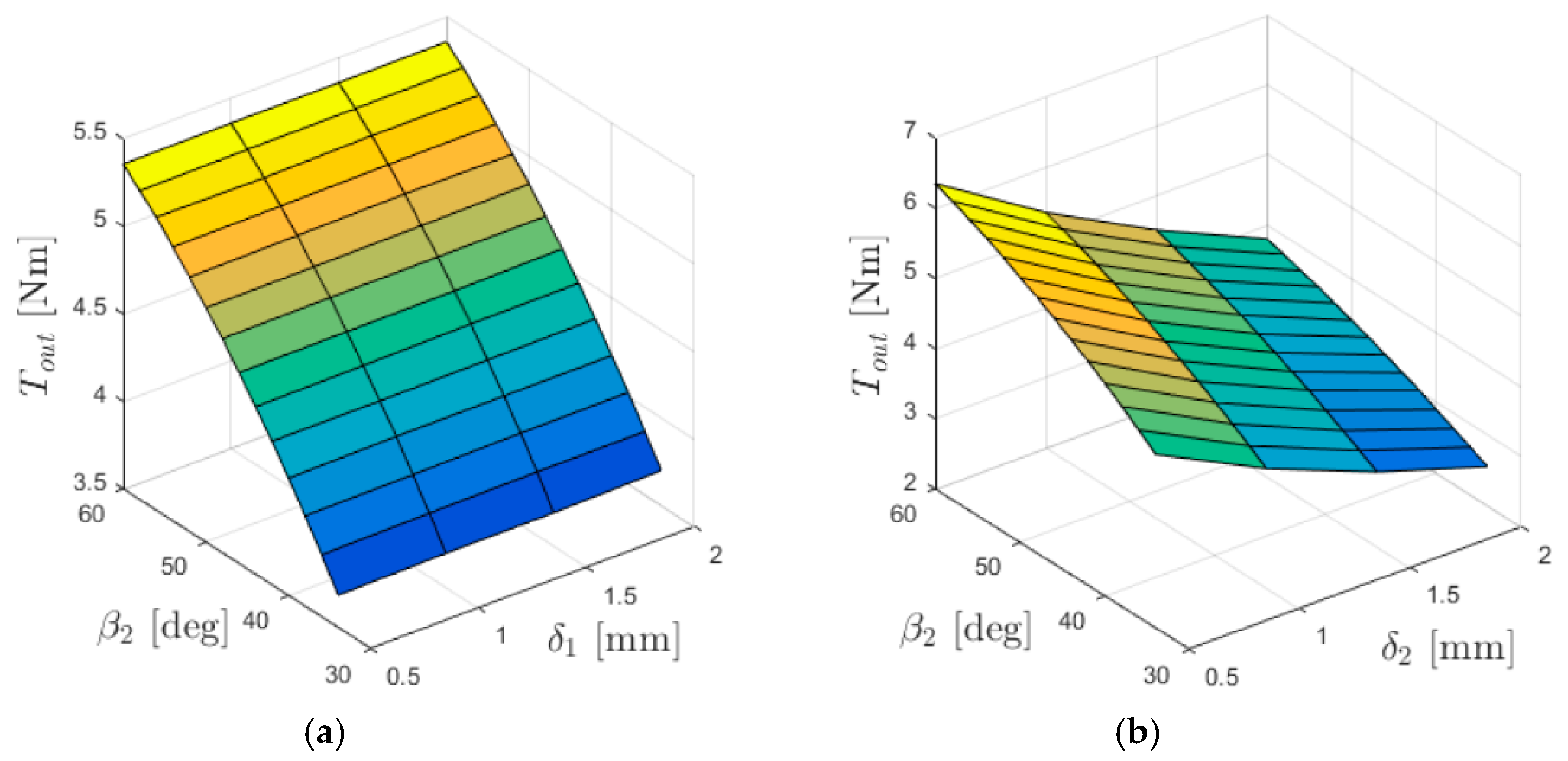
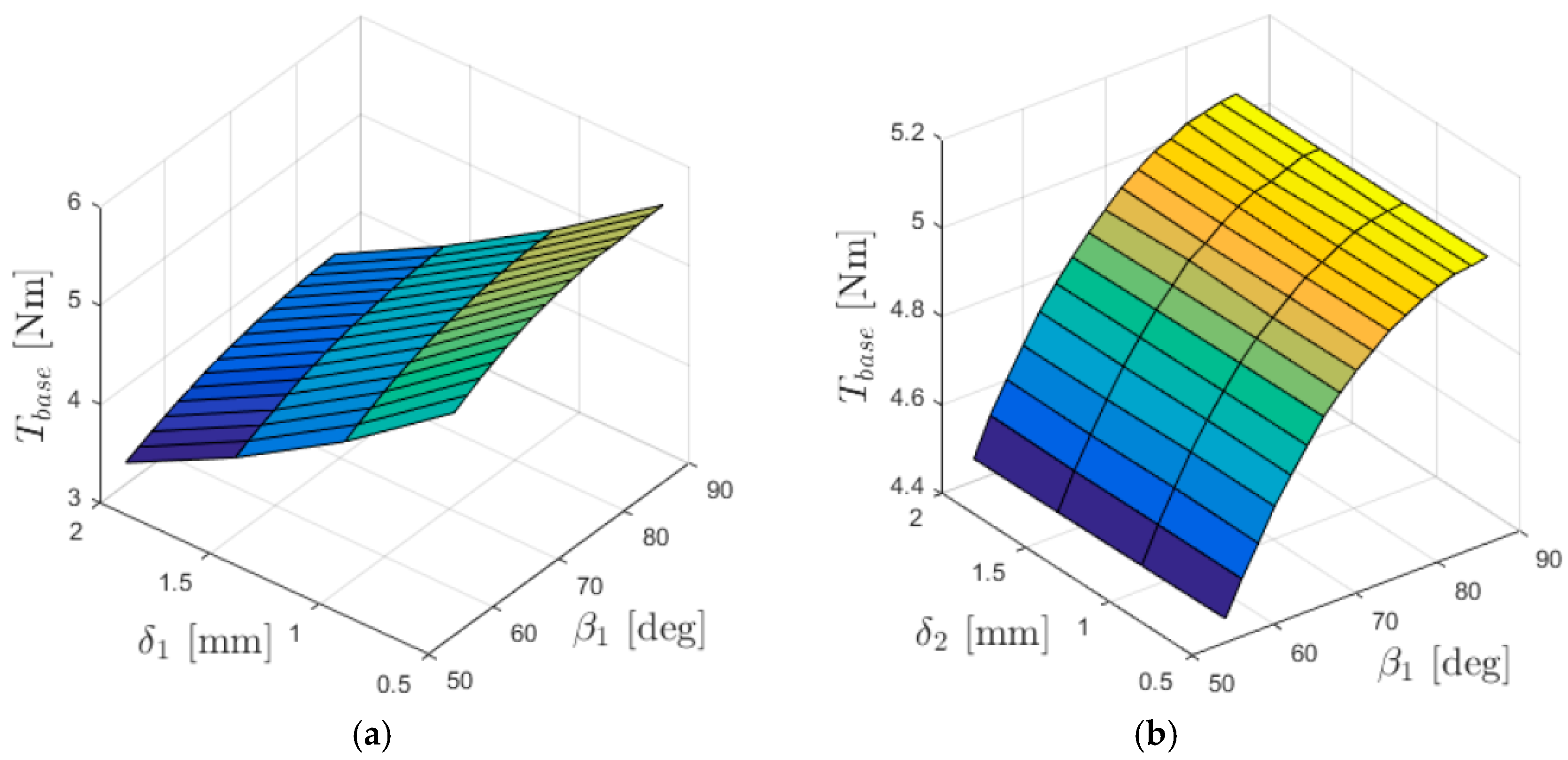
The relationships between the torques acting on individual gear rings and the lengths of the air gaps (between the immovable ring and the intermediate ring—δ1, and between the intermediate ring and the output ring—δ2) are presented in Figure 5, Figure 6 and Figure 7.
Assuming proper design of the magnetic circuit, namely ensuring sufficient cross-sections of the ferromagnetic yokes formed by ferromagnetic discs of the MPG, the length of the air gap has a decisive influence on the reluctance of the magnetic circuit of the considered gear. In analytical methods, for simple magnetic circuits, the magnetic reluctance of the air gap is calculated according to the following relation:
R μ δ = l μ 0 S  
where l is the length of the air gap (the path of the magnetic flux in the circuit), μ0—the magnetic permeability of vacuum, S—the cross-sectional area through which the flux passes.
In the considered transmission, defining the length l and the area S is complicated due to the complex nature of the magnetic circuit structure. Nevertheless, obviously an increase in the air gap length will lead to an increase in the reluctance for the magnetic flux. In turn, the increase in reluctance results in a decrease in the magnetic flux density in the air gap, which translates into a reduction in the interaction force between the magnets and, consequently, a decrease in torque.
From the graphs shown in Figure 5, it can be concluded that the output torque Tout depends on the length of the air gap δ2, while it is independent of δ1. Reducing the length of the air gap between the intermediate and the output ring results in an increase in the torque acting on the output ring at a given internal load angle.
From the graphs shown in Figure 6, it can be inferred that the torque acting on the immovable ring Tbase, depends on the length of the air gap δ1, whereas it is independent of δ2. Similarly to the relationship of Tout with δ2, the value of Tbase increases as the air gap length decreases for a given internal load angle.
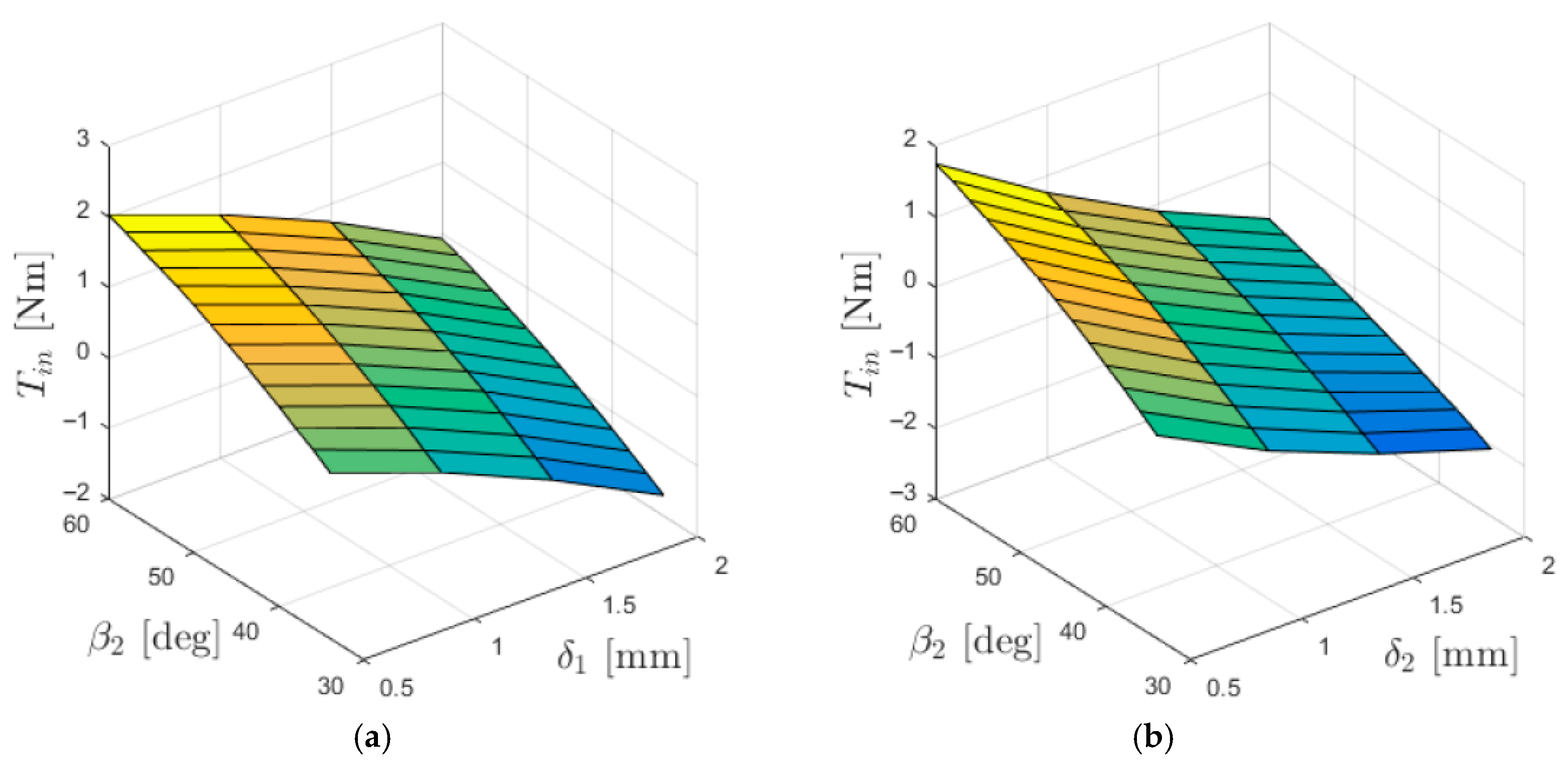
The dependence of the input torque Tin on the lengths of the air gaps between the cooperating rings (Figure 7) is significantly more complex than in the case of Tbase and Tout. The input torque is influenced by the distribution of the magnetic field in both air gaps, and therefore its value is affected by the lengths of both δ1 and δ2.

3.2. Investigation of the Influence of Magnet Dimensions

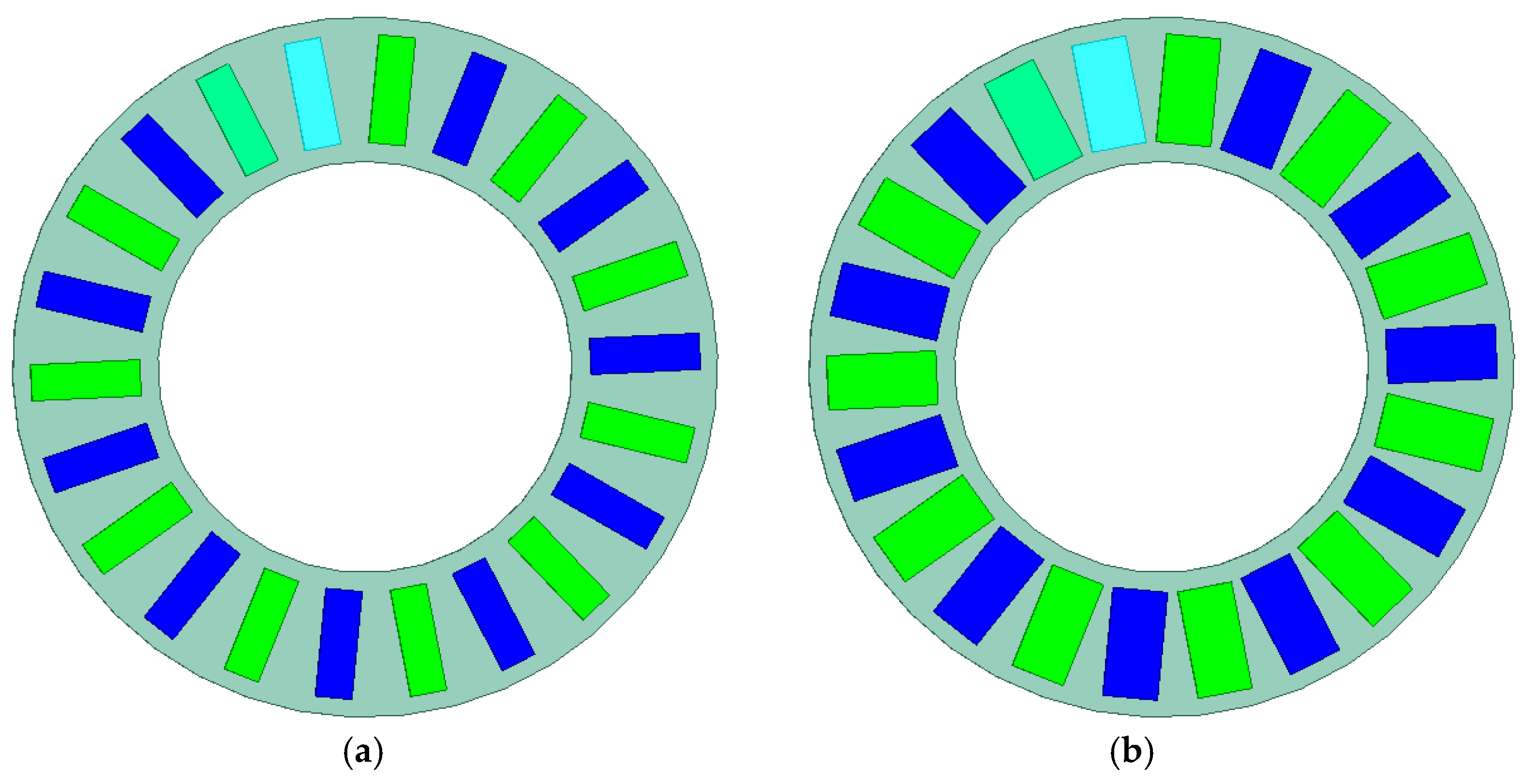
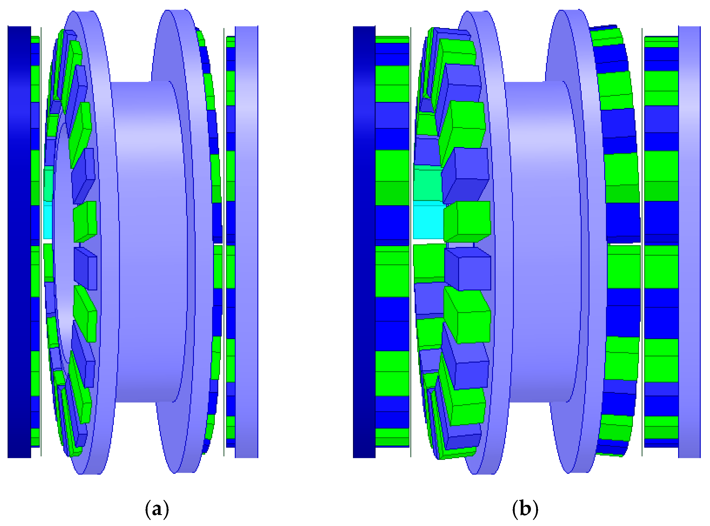
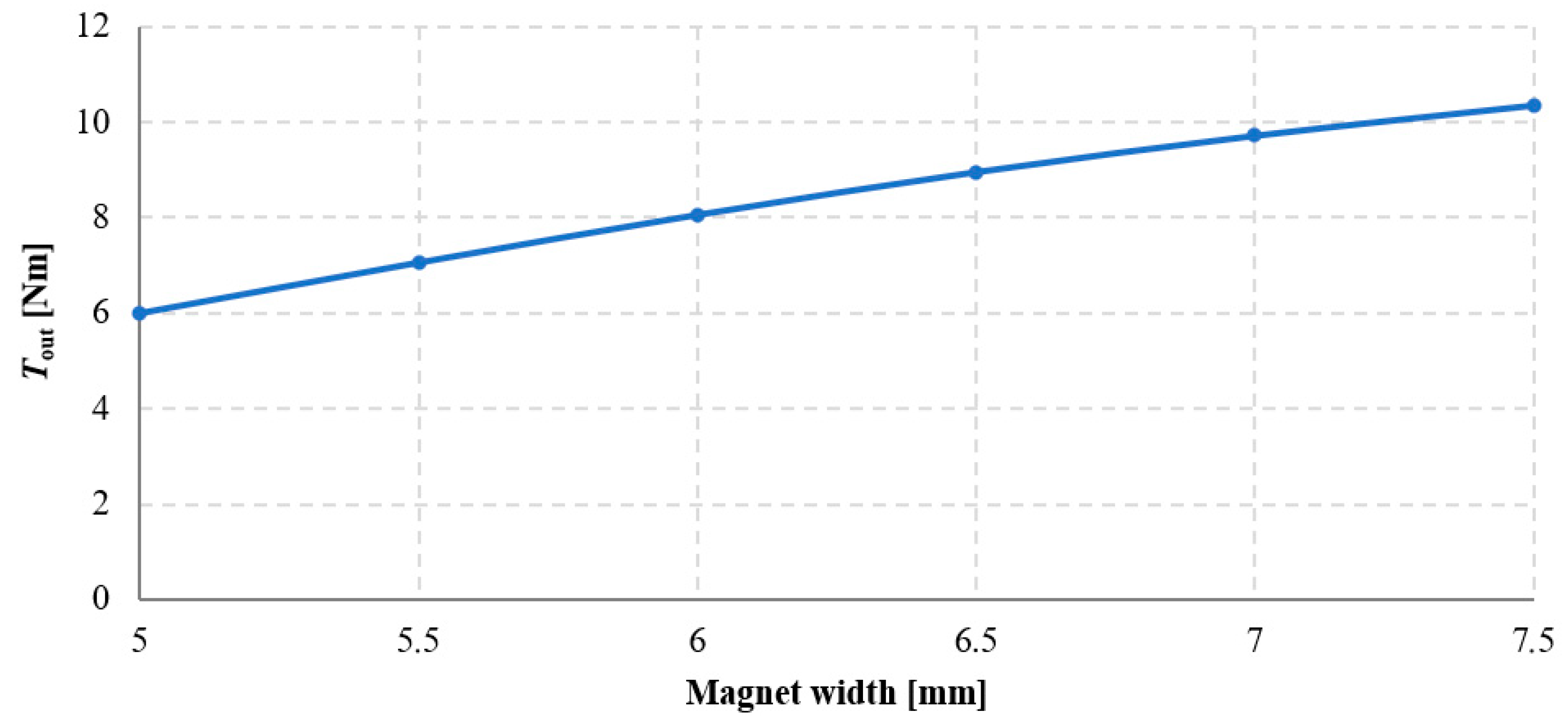
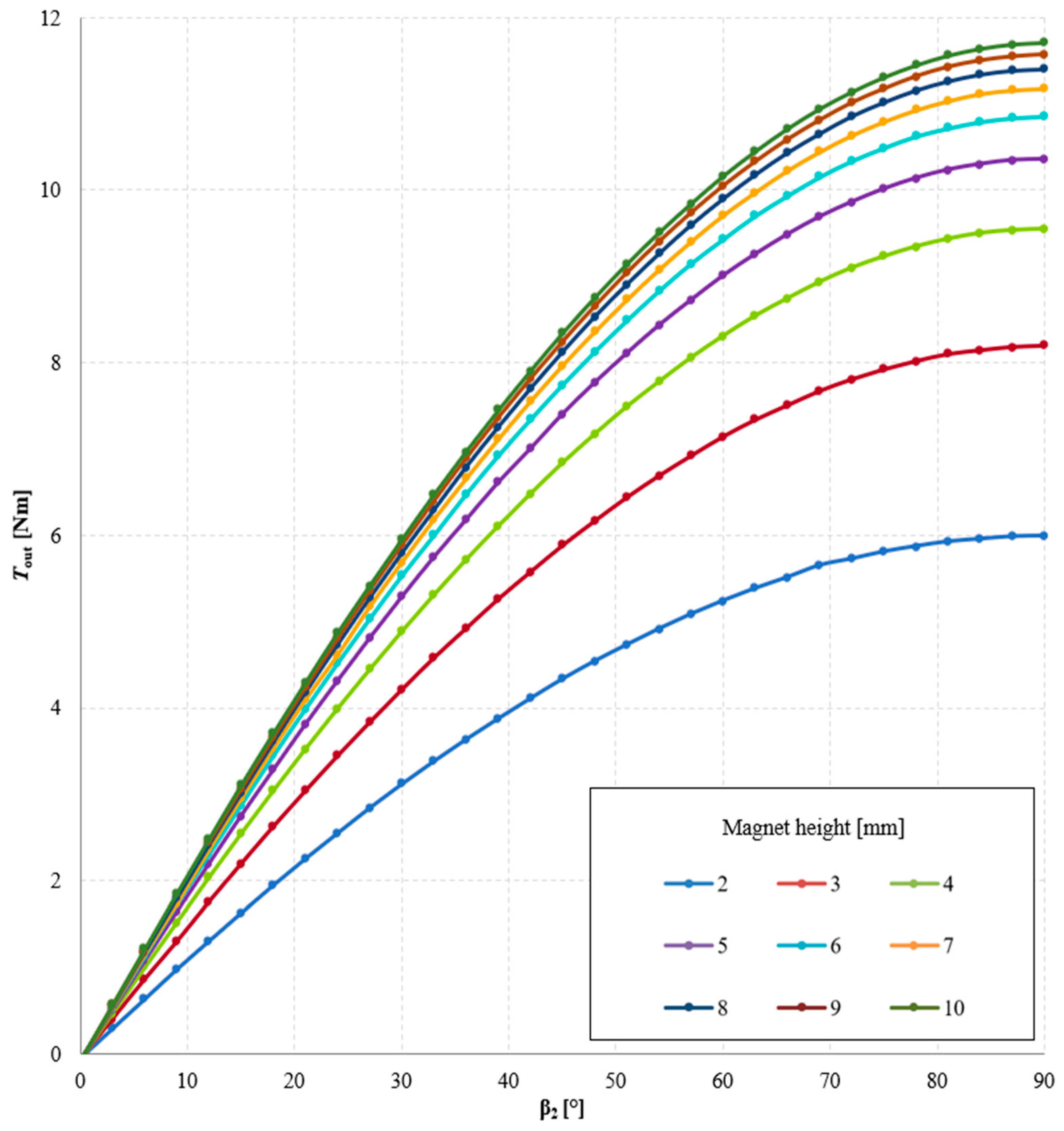
A study was also conducted on the influence of the width and height of the magnets on the torque acting on the output ring of the gear. First, with a constant magnet height of 5 mm, calculations were performed for magnet widths ranging from 5 to 7.5 mm. Then, for the maximum magnet width (7.5 mm), the effect of magnet height (ranging from 2 to 10 mm) on the generated output torque was investigated. Figure 8 shows the geometry of the immovable ring with magnets of 5 mm width (Figure 8a) and 7.5 mm width (Figure 8b), while Figure 9 presents the geometry of the MPG with magnets of 7.5 mm width and heights of 2 mm (Figure 9a) and 8 mm (Figure 9b).
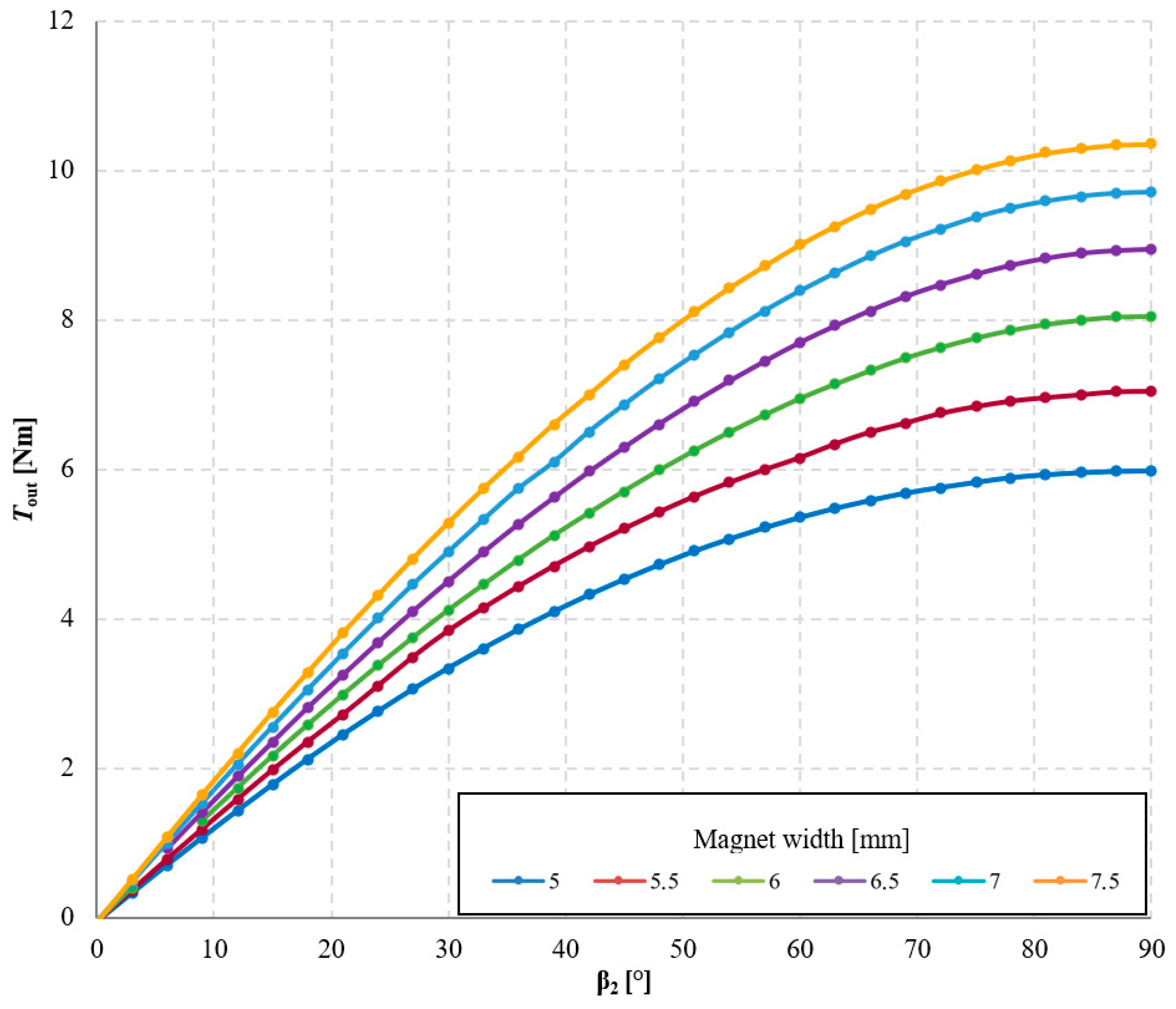
The results of the study on the influence of magnet width on the torque acting on the output ring of the transmission are presented in Figure 10 and Figure 11.
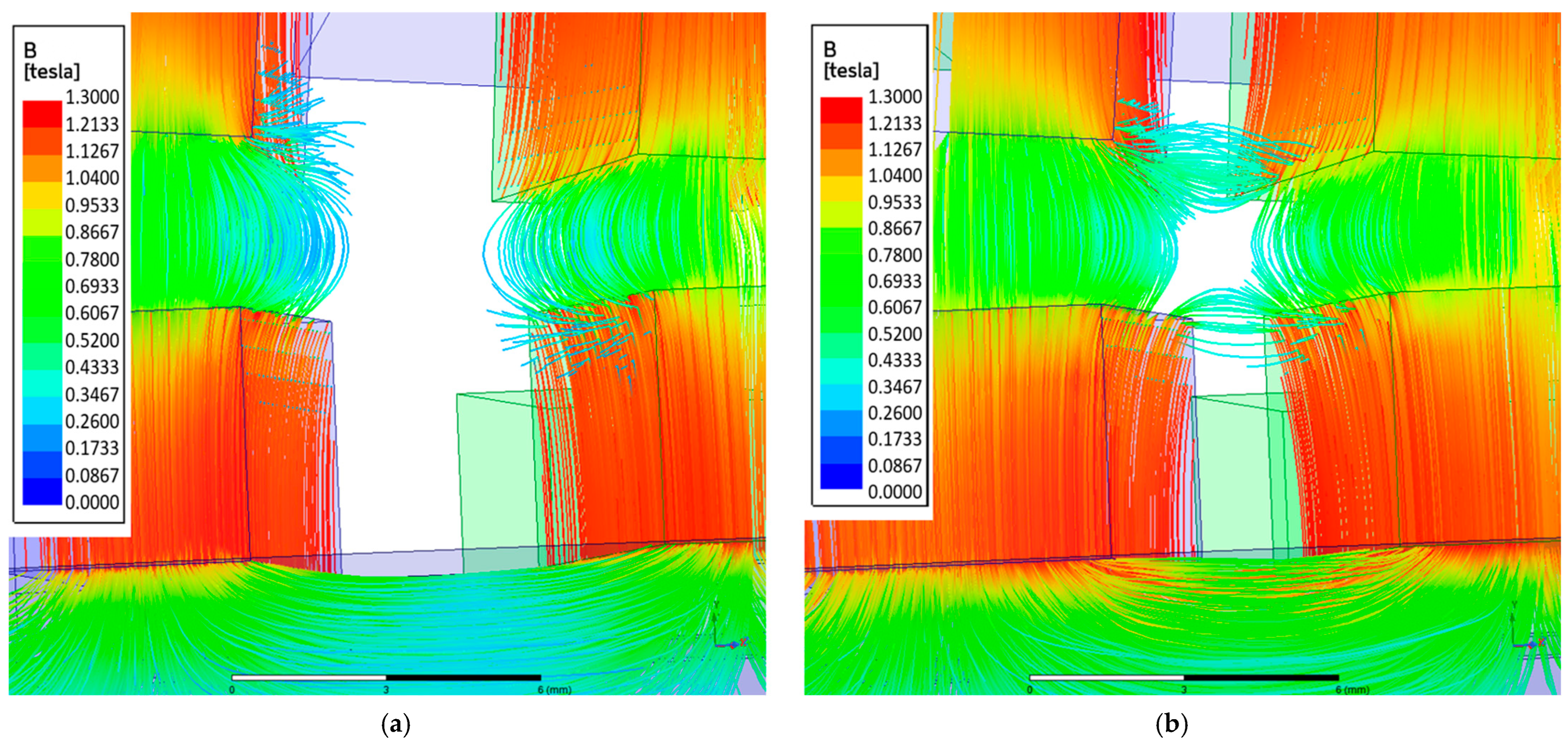
Based on these results, it can be concluded that as the magnet width increases, the torque acting on the output ring also increases. The torque acting on magnetically active components of the MPG is calculated as an integral of the Maxwell stress tensor components over the integration surface located in the air region surrounding the magnetically active materials of each element. Therefore, the larger the magnetically active surface, the greater the achievable torque. However, this relationship is nonlinear, and the cause of this nonlinearity is the presence of flux leakage. This phenomenon occurs when part of the magnetic flux flows to an adjacent magnet on the same ring, thereby reducing the main flux directed toward the air gap. The occurrence of flux leakage can be observed in the magnetic flux distributions shown in Figure 12. It is evident that in the case of wider magnets, the flux leakage is significantly greater. Consequently, increasing the magnet width by 0.5 mm—from 5 mm to 5.5 mm—results in an increase of Tout by approximately 1.07 Nm, whereas an identical increase in width from 7 mm to 7.5 mm results in a smaller torque increase torque Tout about 0.64 Nm.
Referring to the classical magnetic circuits of electrical machines with permanent magnets, the concept of pole pitch coverage by the permanent magnet (magnet span relative to the pole pitch) [20] can be applied here. It should be noted that when magnets of 5 mm width are used, the pole pitch coverage on individual rings is approximately 50%, whereas for 7.5 mm magnets it reaches about 75%. The reduction in the increment of useful torque for increased magnet width in the analyzed transmission configuration is related to the adopted shape of the permanent magnets. Higher values of pole pitch coverage can be achieved after modifying the magnet shape, described in Section 3.3.
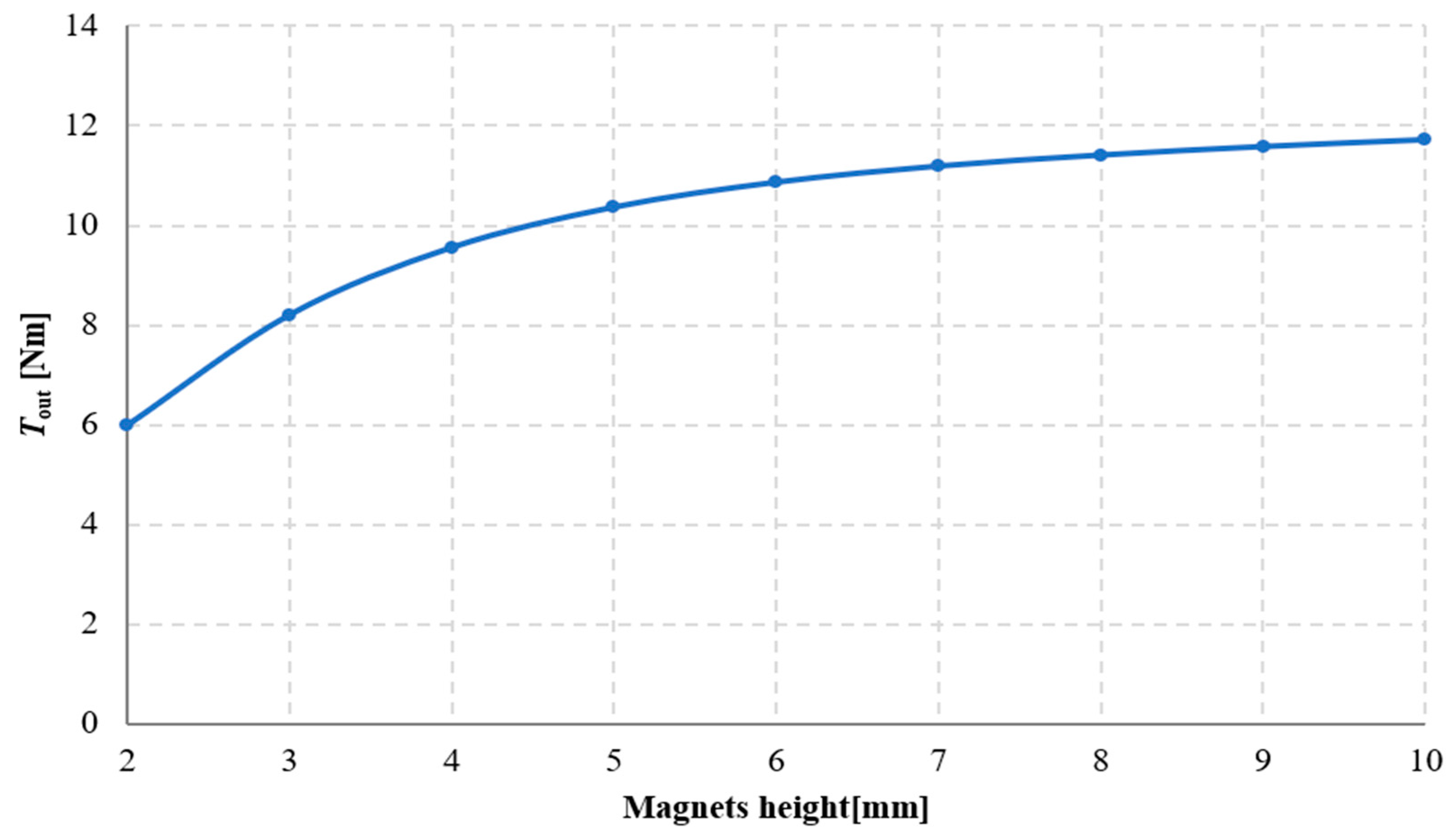
The results of the study on the influence of magnet height on the torque acting on the output ring of the gear are presented in Figure 13 and Figure 14. From these results, it can be concluded that the torque acting on the output ring increases with magnet height. This is directly related to the increase in the magnetomotive force of the magnet. In magnetic circuits with permanent magnets, the magnet height—defined as the dimension of the magnet along the magnetization direction—has a direct impact on the value of the magnetomotive force. In general, the magnetomotive force of a magnet can be expressed as:
Θ = H m ·   l
where Θ is the magnetomotive force, Hm—the magnetic field strength for the considered material and operating point, and l—the magnet height in the direction of magnetization.
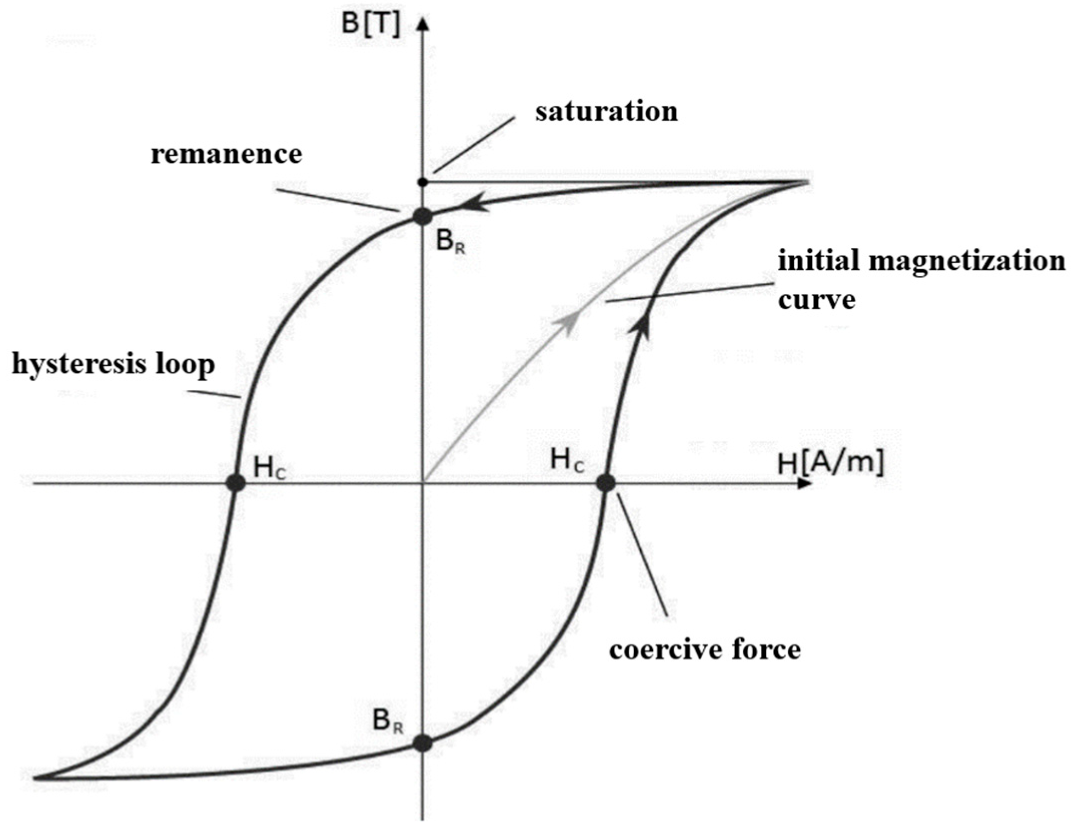
Figure 15 presents an exemplary B–H hysteresis loop, which describes the behavior of a ferromagnetic material in a magnetic field. When a ferromagnet is placed in an external magnetic field of increasing intensity H, the magnetic flux density B rises until saturation is reached. When the external field intensity H is then reduced to zero, the magnetic flux density B attains the value Br (referred to as remanent flux density or remanence). Subsequently, when the field direction is reversed, the flux density decreases until it reaches zero at a field intensity equal to Hc. Further increasing the field intensity again leads to a rise in flux density (in the opposite direction) until saturation is reached [21].
Thus, a permanent magnet in a closed ferromagnetic circuit (without an air gap and assuming infinite permeability of the ferromagnetic core) has a remanent flux density Br, and its operating point is indicated in Figure 15 by point a. When an air gap is introduced into the circuit, the magnetic reluctance of the circuit increases, the magnetic flux density in the core decreases, and the operating point shifts along the hysteresis loop to point b [22].
According to Ampère’s law, the magnetomotive force Θ in a given magnetic circuit balances the magnetic voltages resulting from the magnetic reluctance and the generated magnetic flux ϕ. Neglecting the reluctance of the core (assuming that the magnetic permeability of the ferromagnetic core tends to infinity), it can therefore be assumed that the value of the magnetic flux in the considered circuit depends on the magnetomotive force produced by the permanent magnet and on the magnetic reluctance of the air gap Rμδ. This relationship can thus be expressed by the following equation:
H m · l =     R μ δ · ϕ .
The magnetic flux, in turn, depends on the active surface area of the magnet Sm and the magnetic flux density Bm at the operating point of the magnet:
ϕ = B m · S m
With a constant air gap length (and thus a constant Rμδ, increasing the magnet height reduces the magnetic field strength in the permanent magnet Hm, and consequently, the magnetic flux density in the analyzed circuit increases in accordance with the recoil line [23]. This naturally leads to an increase in the torque acting on the output ring. However, the dependence of torque on magnet height l is nonlinear, since as l increases, the operating point approaches the value of Br, and results in worsening exploitation of PM material (in terms of maximal energy product BHmax [24]. The analysis presented in Figure 15 shows that the difference in the maximum value of Tout when the magnet height increases from 2 mm to 3 mm is approximately 2.2 Nm, whereas increasing the magnet height from 9 mm to 10 mm results in a rise in the maximum Tout of only about 0.1 Nm.

3.3. Investigation of the Influence of Magnets Shape

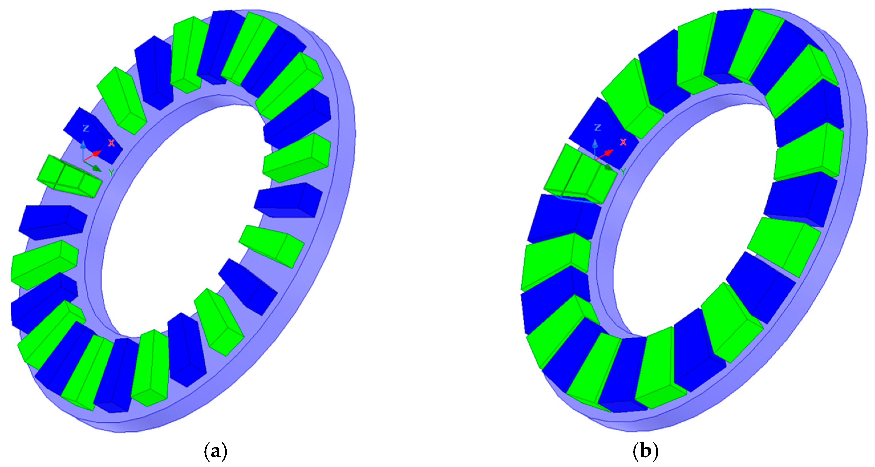
In the simulation studies conducted so far, rectangular permanent magnets with standard dimensions, identical to those used in the prototype, were applied. When such magnets are arranged along the circumference of the ring, the distances between the edges of adjacent magnets are not constant—the magnets are closer to each other on the side facing the center of the ring. Changing the shape of the magnets to those shown in Figure 16 makes it possible to increase the pole pitch coverage with the permanent magnet. This ensures constant distances between the sides of adjacent magnets, which in turn reduces the value of flux leakage while maintaining the active surface area of the magnet.
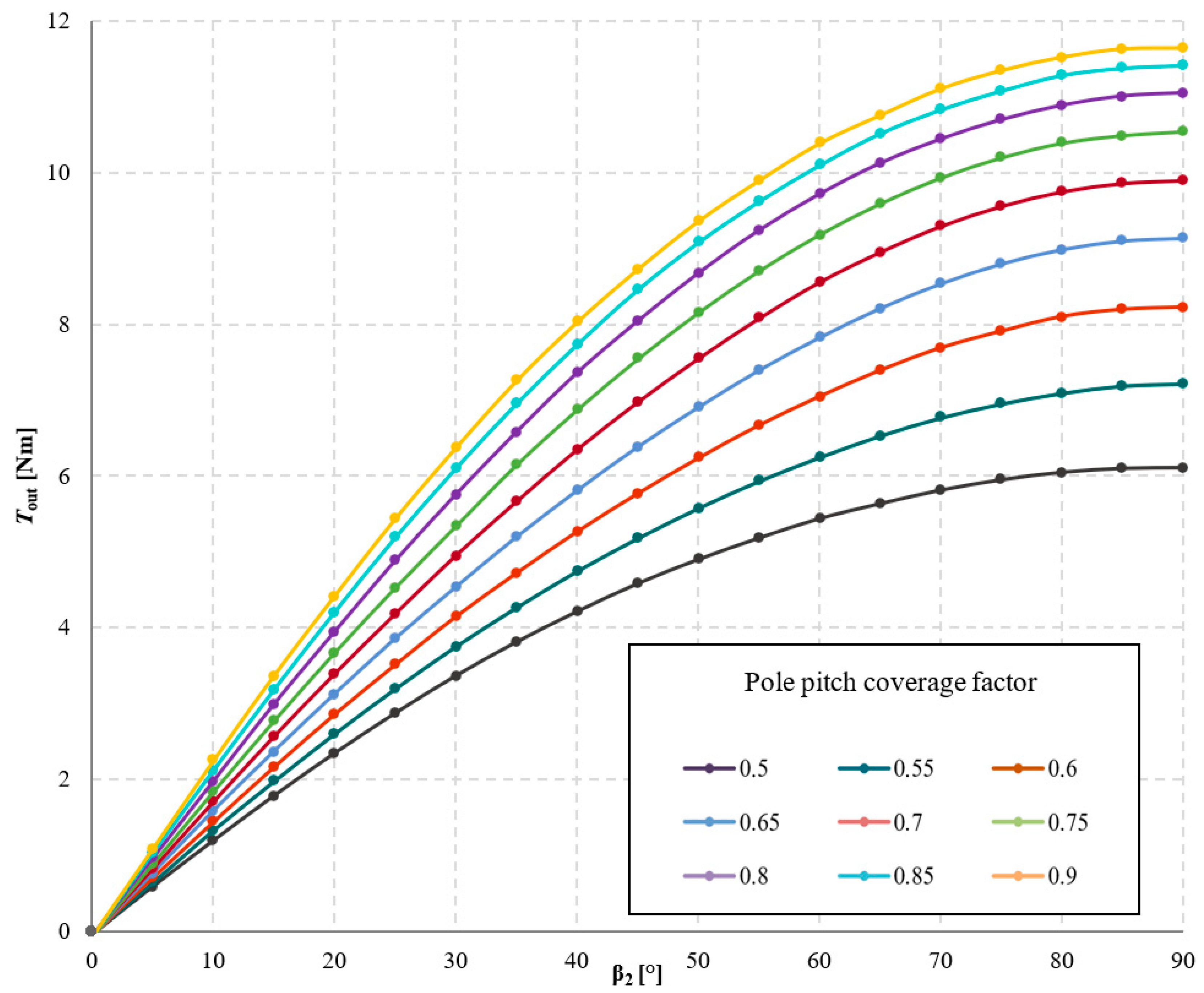
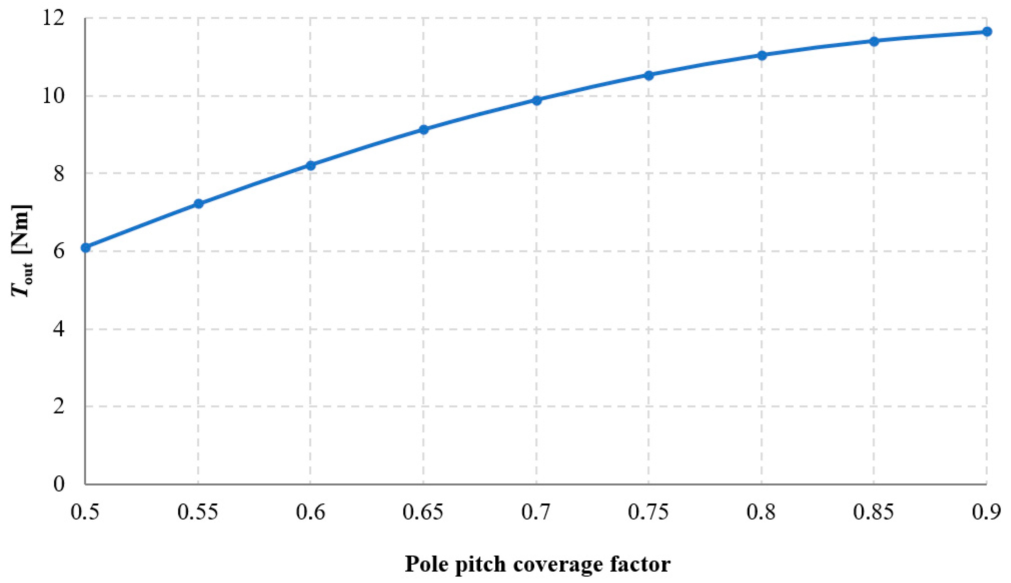
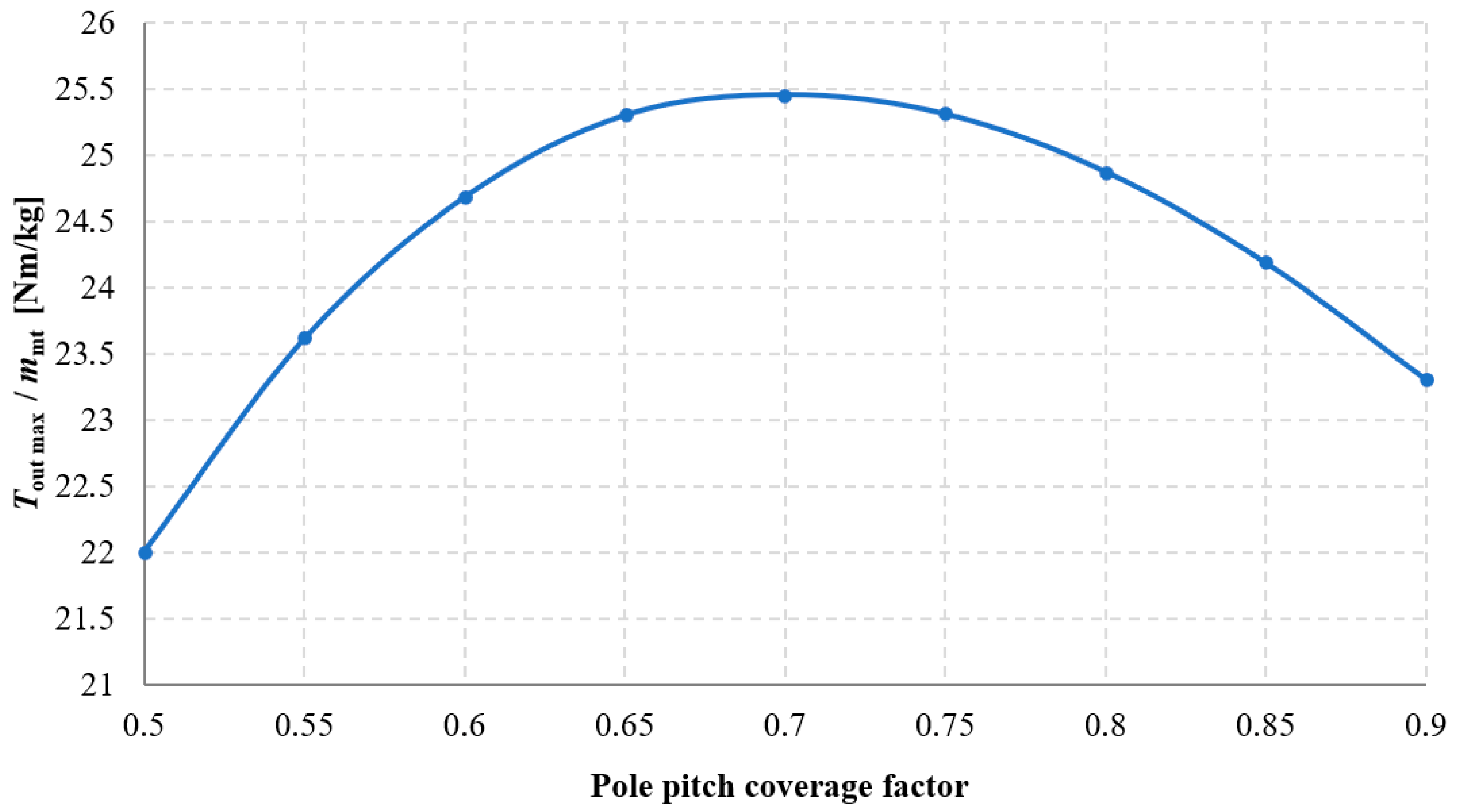
The influence of pole pitch coverage by the permanent magnet on the torque acting on the output ring Tout was investigated, and the results of these studies are presented in Figure 17 and Figure 18. Analyzing the obtained results, it can be stated that as the pole pitch coverage by the magnet increases, the value of Tout also increases. Consequently, the torque density transmitted by the gear also increases. However, this relationship is nonlinear, similarly to the case of changing the width of rectangular magnets, described in Section 3.2. It should be noted that permanent magnets constitute a very significant component of the overall cost of the transmission. Therefore, it was examined for which value of the pole pitch coverage factor the efficiency of permanent magnet utilization—understood as the ratio of the maximum obtainable torque to the mass of the applied permanent magnets—is most favorable. This relationship is shown in Figure 19. Hence, it should be considered whether, in some applications, it may be more advantageous to increase the distance between the magnets at the expense of achieving a lower transmitted torque density.

3.4. Investigation of the Influence of Precession Angle

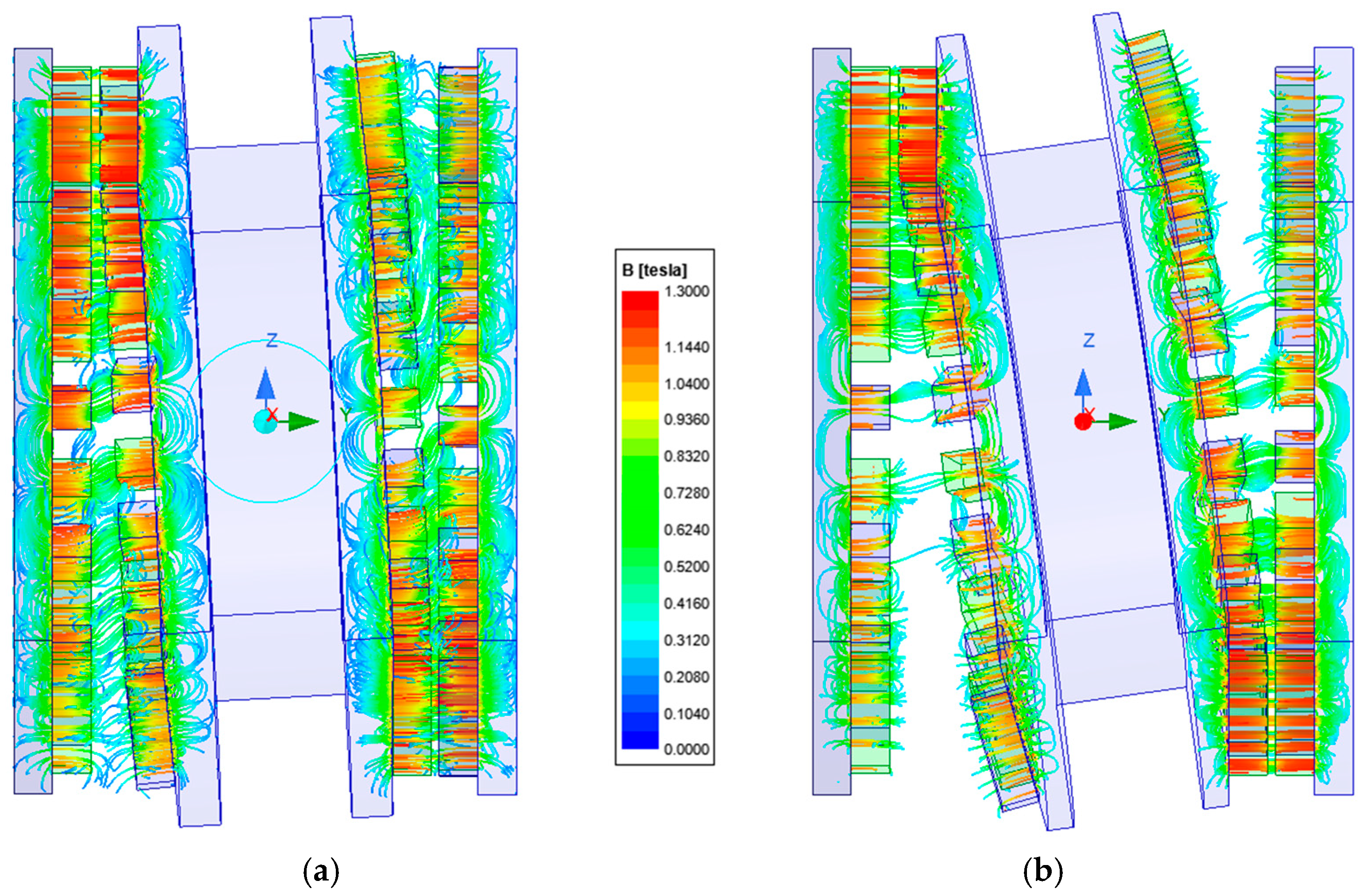
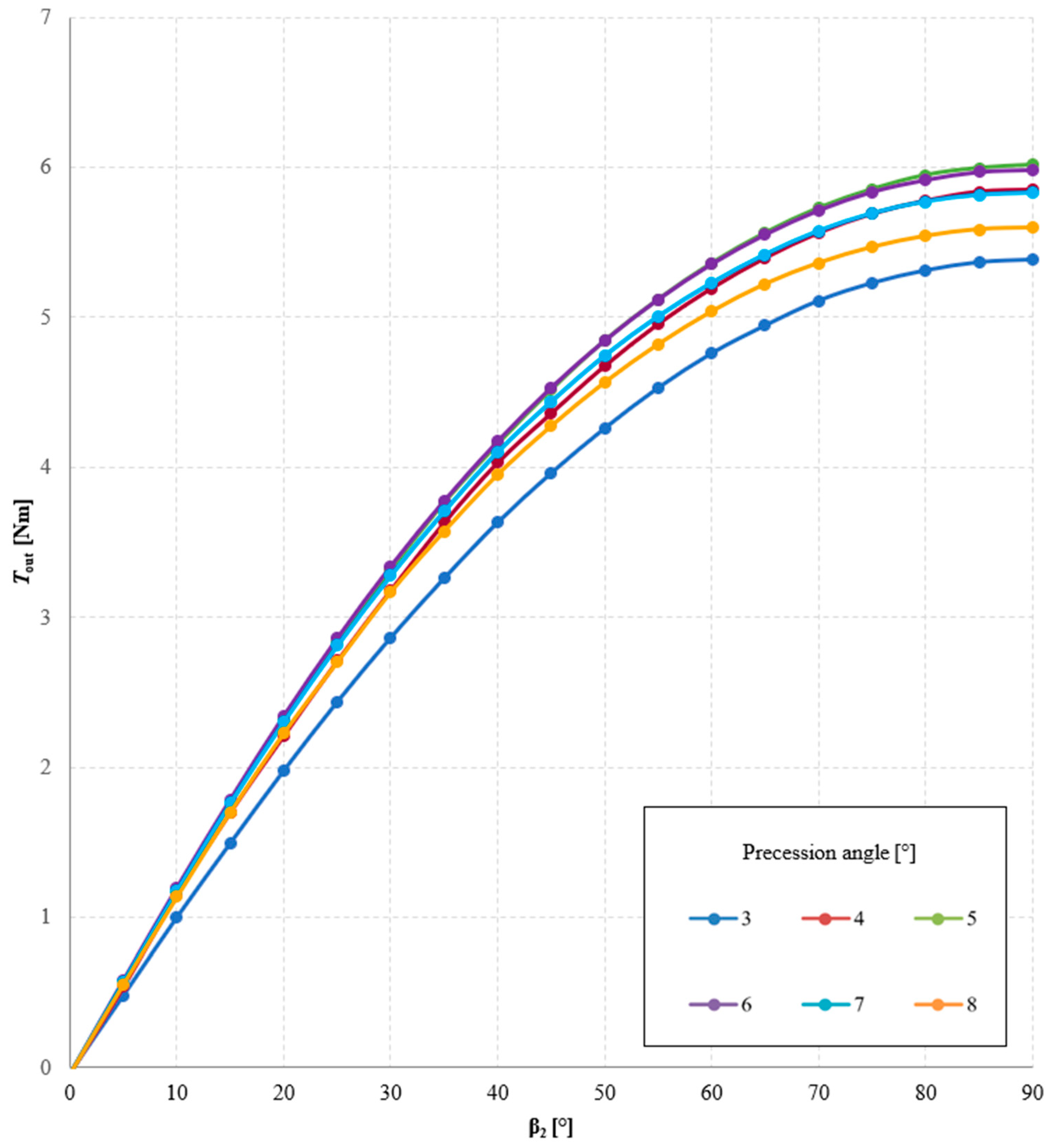
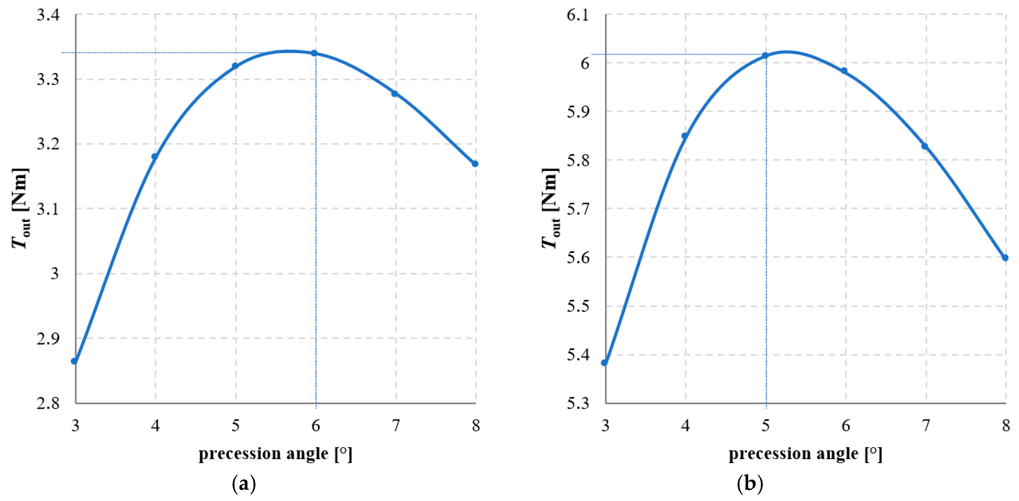
The precession angle, defined as the angle between the axis of the intermediate ring and the main axis of the gear, was also found to be a significant factor affecting the torque transmitted by the gear. Figure 20 presents the magnetic flux lines distribution for two different precession angles. Figure 21 and Figure 22 show the dependence of the torque acting on the output ring Tout on the precession angle. A too small precession angle reduces the air gap length between magnets that do not participate in torque transmission, causing some of them to generate torque in the opposite direction to that intended. Conversely, a too large precession angle decreases the magnetically active surface area between the cooperating rings, which also negatively affects the torque value.
In the analyzed MPG design with a gear ratio of 1/144 and magnets of dimensions 5 × 5 × 15 mm, the maximum values of Tout were obtained for precession angles of 5° and 6°, depending on the internal load angle β2. Analyzing the graphs presented in Figure 22, it can also be observed that decreasing the precession angle from its optimal value has a greater impact on the reduction of Tout than increasing the precession angle.

4. Conclusions

The conducted research enabled a comprehensive understanding of how the geometrical parameters and the magnetic circuit configuration of a two-stage magnetic precession gear affect the magnetic torques acting on its active components. The finite element analyses confirmed that variations in air gap length, magnet dimensions, pole pitch coverage, and precession angle significantly influence the torque transmission capability of the gear.
The results indicated that reducing the air gap length leads to higher transmitted torque. Increasing the magnet width and height also enhances the torque, though this dependence is nonlinear due to flux leakage and magnetic saturation. The analysis of impact of pole pitch coverage by the magnet was shown to be a crucial factor: higher coverage increases torque density but may reduce the effectiveness of magnet utilization, which is vital from both design and economic perspectives. The efficiency of permanent magnet utilization turned out to be the highest for the pole pitch coverage factor of 0.7. The precession angle was also identified as an important parameter. In the presented gearbox maximum torque was achieved for a precession angle between 5 and 6 degrees. Deviations from this value negatively impacted performance. In all of the analyses, the maximum torque was obtained for the output load angle close to 90 degrees.
Overall, the study highlights the importance of precisely selecting and adjusting geometrical parameters in magnetic precession gear design. By carefully balancing air gap dimensions, magnet geometry, pole pitch coverage and precession angle, it is possible to significantly improve torque transmission while ensuring efficient use of permanent magnets. These insights provide a valuable foundation for further development of high-torque-density, low-maintenance magnetic transmission systems suitable for demanding applications such as renewable energy and marine propulsion.

Author Contributions

Conceptualization, L.M. and C.J.; methodology, L.M. and C.J.; software, C.J.; investigation, L.M. and C.J.; resources, L.M. and M.M.; writing—original draft preparation, L.M. and M.M.; writing—review and editing, C.J.; visualization, L.M.; supervision, C.J. All authors have read and agreed to the published version of the manuscript.

Funding

This research was supported by the National Ministry of Science and Higher Education in Poland as a part of research subsidy (project nos. 0212/SBAD/0616 and 0614/SBAD/1603).

Institutional Review Board Statement

Not applicable.

Informed Consent Statement

Not applicable.

Data Availability Statement

The original contributions presented in this study are included in the article. Further inquiries can be directed to the corresponding author.

Conflicts of Interest

The authors declare no conflicts of interest. The founding sponsors had no role in the design of the study; in the collection, analyses, or interpretation of the data; in writing the manuscript; and in the decision to publish the results.

Abbreviations

The following abbreviations are used in this manuscript:
FEMFinite Element Method
MGMagnetic gear
MPGMagnetic precession gear

References

  1. Crider, J.M.; Scott, D.S. An Inner Rotor Flux-Modulated Permanent Magnet Synchronous Machine for Low-Speed High-Torque Applications. IEEE Trans. Energy Convers. 2015, 30, 1247–1254. [Google Scholar] [CrossRef]
  2. Wang, Z.; Fu, W.; Song, J.; Chen, P.; Qiao, Z.; Bi, Y. Optimization of Gear Ratio and Torque Density of Magnetic Gears Based on Genetic Algorithm. In Proceedings of the 10th Frontier Academic Forum of Electrical Engineering (FAFEE2022), Xi’an, China, 25 August 2022; Dong, X., Yang, Q., Ma, W., Eds.; Springer Nature: Singapore, 2023; pp. 27–36. [Google Scholar]
  3. Molokanov, O.; Dergachev, P.; Kiruhin, V.; Kurbatov, P. Analyses and Experimental Validation of Coaxial Magnetic Planetary Gear. In Proceedings of the International Symposium on Electrical Apparatus and Technologies, SIELA—Proc., Bourgas, Bulgaria, 12–15 June 2024; IEEE Computer Society: Washington, DC, USA, 2014. [Google Scholar]
  4. Kucuk, F.; Mousavi, S. Development of a Novel Coaxial Magnetic Gear. In Proceedings of the International Conference Electrrical Machine, Drives Power Systems ELMA—Proc., Bourgas, Bulgaria, 3–6 June 2020; Institute of Electrical and Electronics Engineers Inc.: New York, NY, USA, 2017; pp. 22–25. [Google Scholar]
  5. Jian, L.; Chau, K.T.; Gong, Y.; Jiang, J.Z.; Yu, C.; Li, W. Comparison of Coaxial Magnetic Gears with Different Topologies. IEEE Trans. Magn. 2009, 45, 4526–4529. [Google Scholar] [CrossRef]
  6. Khan, S.A.; Afsari, P.; Gardner, M.C. Comparison between Flux Angle Mapping and Cycloidal Magnetic Gears for High Gear Ratio Applications. In Proceedings of the IEEE Energy Conversion Conference and Expo ECCE—Proc., Phoenix, AZ, USA, 20–24 October 2024; Institute of Electrical and Electronics Engineers Inc.: New York, NY, USA, 2024; pp. 5337–5342. [Google Scholar]
  7. Kołodziej, J.; Gabor, R.; Kowol, M.; Łukaniszyn, M. Theoretical and Experimental Comparison of Gear Systems: Planetary Mechanical Transmission and Coaxial Magnetic Gear. Bull. Pol. Acad. Sci. Tech. Sci. 2024, 72, 150334. [Google Scholar] [CrossRef]
  8. Nicolas, W. Frank; Siavash Pakdelian; Hamid, A. Toliyat Passive Suppression of Transient Oscillations in the Concentric Planetary Magnetic Gear. IEEE Trans. Energy Convers. 2011, 26, 933–939. [Google Scholar] [CrossRef]
  9. Frank, N.W.; Pakdelian, S.; Toliyat, H.A. A Magnetic Gear with Passive Transient Suppression Capability. In Proceedings of the IEEE Electric Ship Technologies Symposium, Alexandria, VA, USA, 10–13 April 2011; ESTS: Exeter, UK, 2011; pp. 326–329. [Google Scholar]
  10. Pakdelian, S.; Frank, N.W.; Toliyat, H.A. Damper Windings for the Magnetic Gear. In Proceedings of the IEEE Energy Conversion Congress and Exposition: Energy Conversion Innovation Clean Energy Future, ECCE, Proc., Phoenix, AZ, USA, 7–22 September 2011; pp. 3974–3981. [Google Scholar]
  11. Bai, J.; Liu, Y.; Lin, J.; Song, Z.; Wang, W. Analysis of Torque Characteristics of Magnetic Gears. In Proceedings of the International Conference on Electrical Machines and Systems, ICEMS, Berlin, Germany, 2–5 September 2014; Institute of Electrical and Electronics Engineers Inc.: New York, NY, USA, 2014; pp. 2164–2169. [Google Scholar]
  12. Hao, X.; Hao, W.; Wang, Q.; Pan, D. Free Vibration of Magnetic Gear with Intersecting Axes. Prog. Electromagn. Res. C 2020, 104, 187–199. [Google Scholar] [CrossRef]
  13. Macyszyn, L.; Jedryczka, C.; Mysinski, M. Analysis of a Two-Stage Magnetic Precession Gear Dynamics. Energies 2023, 16, 4484. [Google Scholar] [CrossRef]
  14. Macyszyn, Ł.; Myszkowski, A.; Staniek, R.; Pabiszczak, S. Two-Stage Precession Type Gear: Design, Geometric and Kinematic Analysis; American Society of Mechanical Engineers: Washington, DC, USA, 2018. [Google Scholar]
  15. Macyszyn, Ł.; Jedryczka, C.; Staniek, R. Design and Finite Element Analysis of Novel Two-Stage Magnetic Precession Gear. Int. J. Simul. Model. 2019, 18, 586–595. [Google Scholar] [CrossRef] [PubMed]
  16. Coulomb, J. A Methodology for the Determination of Global Electromechanical Quantities from a Finite Element Analysis and Its Application to the Evaluation of Magnetic Forces, Torques and Stiffness. IEEE Trans. Magn. 1983, 19, 2514–2519. [Google Scholar] [CrossRef]
  17. Macyszyn, L.; Jedryczka, C.; Myszkowski, A. Simulation and Experimental Investigation of a Two-Stage Magnetic Precession Gear. Energies 2021, 14, 1838. [Google Scholar] [CrossRef]
  18. Ionel, D.M.; Eastham, J.F.; Miller, T.J.E.; Demeter, E. Design Considerations for Permanent Magnet Synchronous Motors for Flux Weakening Applications. IEE Proc. -Electr. Power Appl. 1998, 145, 435–440. [Google Scholar] [CrossRef]
  19. Huang, W.; Bettayeb, A.; Kaczmarek, R.; Vannier, J. Optimization of Magnet Segmentation for Reduction of Eddy-Current Losses in Permanent Magnet Synchronous Machine. IEEE Trans. Energy Convers. 2010, 25, 381–387. [Google Scholar] [CrossRef]
  20. Knypiński, Ł. Optymalizacja Silników O Magnesach Trwałych Na Podstawie Polowoobwodowego Modelu Zjawisk Elektomagnetycznych; Rozprawa Doktorska, Politechnika Poznańska: Poznań, Poland, 2016. [Google Scholar]
  21. Korta, J.; Giergiel, M.; Uhl, T. Koncepcja Koła Magnetycznego. Model. Inż. 2011, 41, 173–180. [Google Scholar]
  22. Bolkowski, S. Elektrotechnika 4. Podręcznik; Wydawnictwa Szkolne i Pedagogiczne: Warsaw, Poland, 1995; ISBN 83-02-05981-1. [Google Scholar]
  23. Gieras, J.; Frydrychowicz, G.; Józefowicz, W. Projektowanie Silników Prądu Stałego Małej Mocy o Magnesach Trwałych Wspomagane Maszyną Cyfrową. Przegląd Elektrotechniczny 1978, 4, 152–156. [Google Scholar]
  24. Pyrhönen, J.; Jokinen, T.; Hrabovcova, V. Design of Rotating Electrical Machines; Wiley: Hoboken, NJ, USA, 2008; ISBN 978-0-470-69516-6. [Google Scholar]
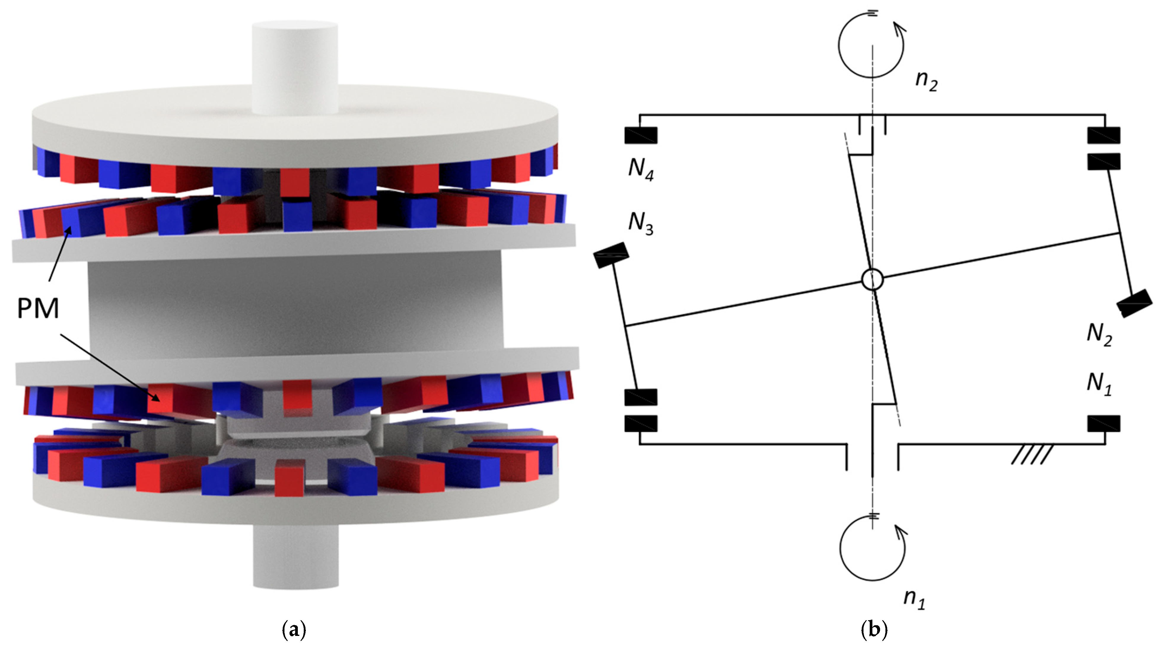
Figure 1. Two-stage magnetic precession gear CAD model (a) and kinematic scheme (b): PM—permanent magnet, n1—input speed, n2—output speed, Nk number of magnets on ring k (k = 1, 2, 3, 4).
Materials 18 05277 g001
Figure 2. Geometries for calculating torques: (a) output ring, (b) intermediate ring (c) immovable ring.
Materials 18 05277 g002
Figure 3. Example of magnetic flux distribution in the air gap between an output ring and an intermediate ring.
Materials 18 05277 g003
Figure 4. Illustration of the load angle changes upon the load torque: (a) β = 0 deg; (b) β = 45 deg; (c) β = 90 deg.
Materials 18 05277 g004
Figure 5. Output torque Tout as a function of the internal load angle β2 and: (a) δ1 (for δ2 = 1 mm); (b) δ2 (for δ1 = 1 mm).
Materials 18 05277 g005
Figure 6. Torque acting on the immovable ring Tbase as a function of the internal load angle β1 and: (a) δ1 (for δ2 = 1 mm); (b) δ2 (for δ1 = 1 mm).
Materials 18 05277 g006
Figure 7. Torque acting on the input ring Tin as a function of the internal load angle β1 and: (a) δ1 (for δ2 = 1 mm); (b) δ2 (for δ1 = 1 mm).
Materials 18 05277 g007
Figure 8. Immovable ring with magnets of 5 mm (a) and 7.5 mm (b) width.
Materials 18 05277 g008
Figure 9. Geometry of MPG with magnets of 7.5 mm width and heights of 2 mm (a) and 8 mm (b).
Materials 18 05277 g009
Figure 10. Torque acting on the output ring, Tout, as a function of the internal load angle β2 and magnet width, for symmetric air gaps δ1 = δ2 = 1 mm, with a constant angle β1 = 30° and a fixed magnet height of 5 mm.
Materials 18 05277 g010
Figure 11. Torque acting on the output ring, Tout, as a function of magnet width for an angle β2 = 90° with a constant magnet height of 5 mm.
Materials 18 05277 g011
Figure 12. Magnetic flux distribution in the air gap between the immovable ring and the intermediate ring for magnet widths: (a) 5 mm; (b) 7.5 mm.
Materials 18 05277 g012
Figure 13. Torque acting on the output ring Tout as a function of the internal load angle β2 and magnet height, for symmetric air gaps δ1 = δ2 = 1 mm, with a constant angle β1 = 30° and a fixed magnet width of 7.5 mm.
Materials 18 05277 g013
Figure 14. Torque acting on the output ring Tout as a function of magnet height for an angle β2 = 90° with a constant magnet width of 7.5 mm.
Materials 18 05277 g014
Figure 15. Example of hysteresis loop of ferromagnetic material [21].
Materials 18 05277 g015
Figure 16. Immovable ring with magnets of a modified shape, providing a pole pitch coverage factor by the magnet equal to: (a) 0.5; (b) 0.9.
Materials 18 05277 g016
Figure 17. Torque acting on the output ring, Tout, as a function of the internal load angle β2 and the pole pitch coverage factor of the permanent magnet, for symmetric air gaps δ1 = δ2 = 1 mm, with a constant angle β1 = 30° and a fixed magnet height of 5 mm.
Materials 18 05277 g017
Figure 18. Torque acting on the output ring, Tout, as a function of the pole pitch coverage factor of the permanent magnet for an angle β2 = 90°, with a constant magnet height of 5 mm.
Materials 18 05277 g018
Figure 19. Ratio of Tout to the mass of the applied permanent magnets mpm as a function of the pole pitch coverage factor of the permanent magnet, for β2 = 90° and a constant magnet height of 5 mm.
Materials 18 05277 g019
Figure 20. Magnetic flux distribution for a precession angle of: (a) 3°; (b) 6°.
Materials 18 05277 g020
Figure 21. Torque acting on the output ring, Tout, as a function of the internal load angle β2 and the precession angle, for symmetric air gaps δ1 = δ2 = 1 mm and a constant angle β1 = 30°.
Materials 18 05277 g021
Figure 22. Torque acting on the output ring, Tout, as a function of the precession angle for the internal load angle β2: (a) 30°; (b) 90°.
Materials 18 05277 g022
Disclaimer/Publisher’s Note: The statements, opinions and data contained in all publications are solely those of the individual author(s) and contributor(s) and not of MDPI and/or the editor(s). MDPI and/or the editor(s) disclaim responsibility for any injury to people or property resulting from any ideas, methods, instructions or products referred to in the content.