
Experimental Investigation on Macroscopic and Microscopic Mechanical Properties of Geopolymer-Stabilized Macadam


Abstract
1. Introduction
2. Materials and Methods
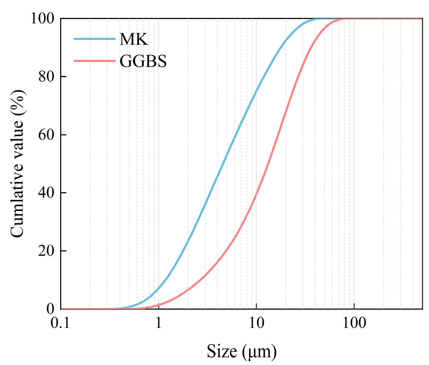
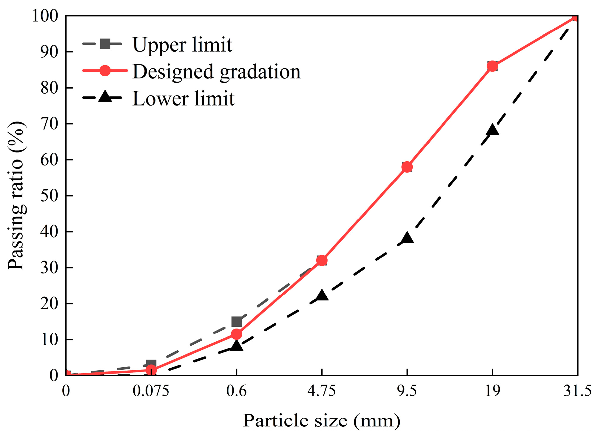
2.1. Raw Materials
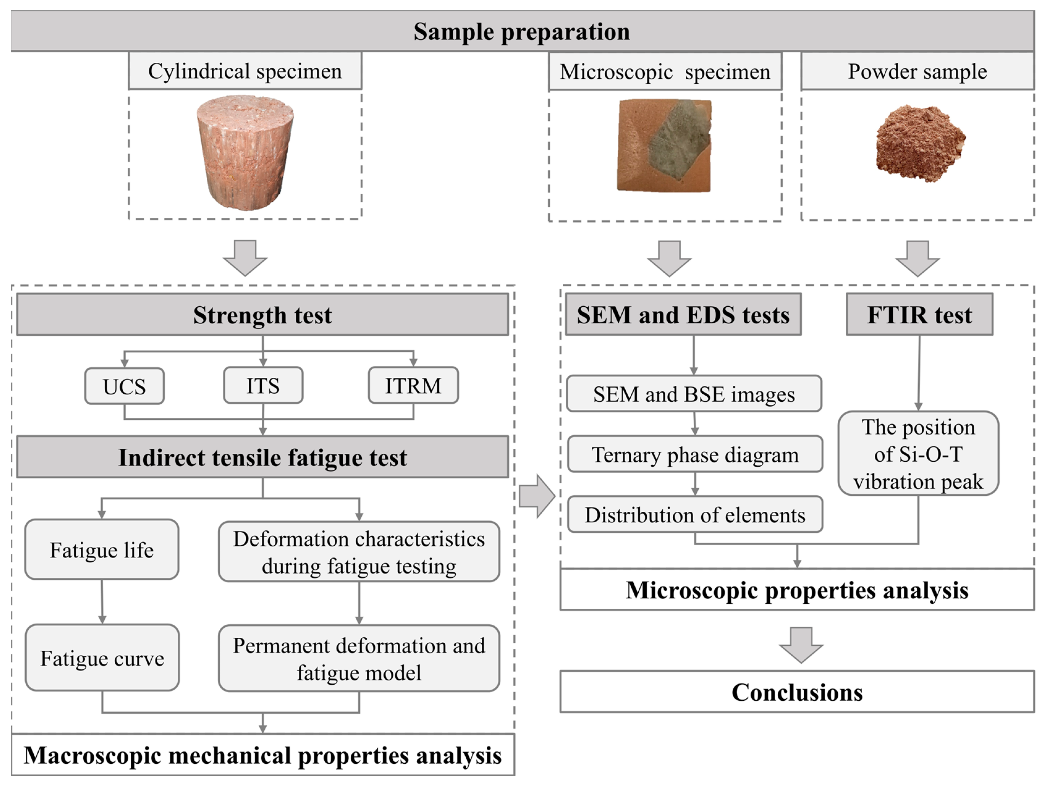
2.2. Sample Preparation
2.3. Strength Test
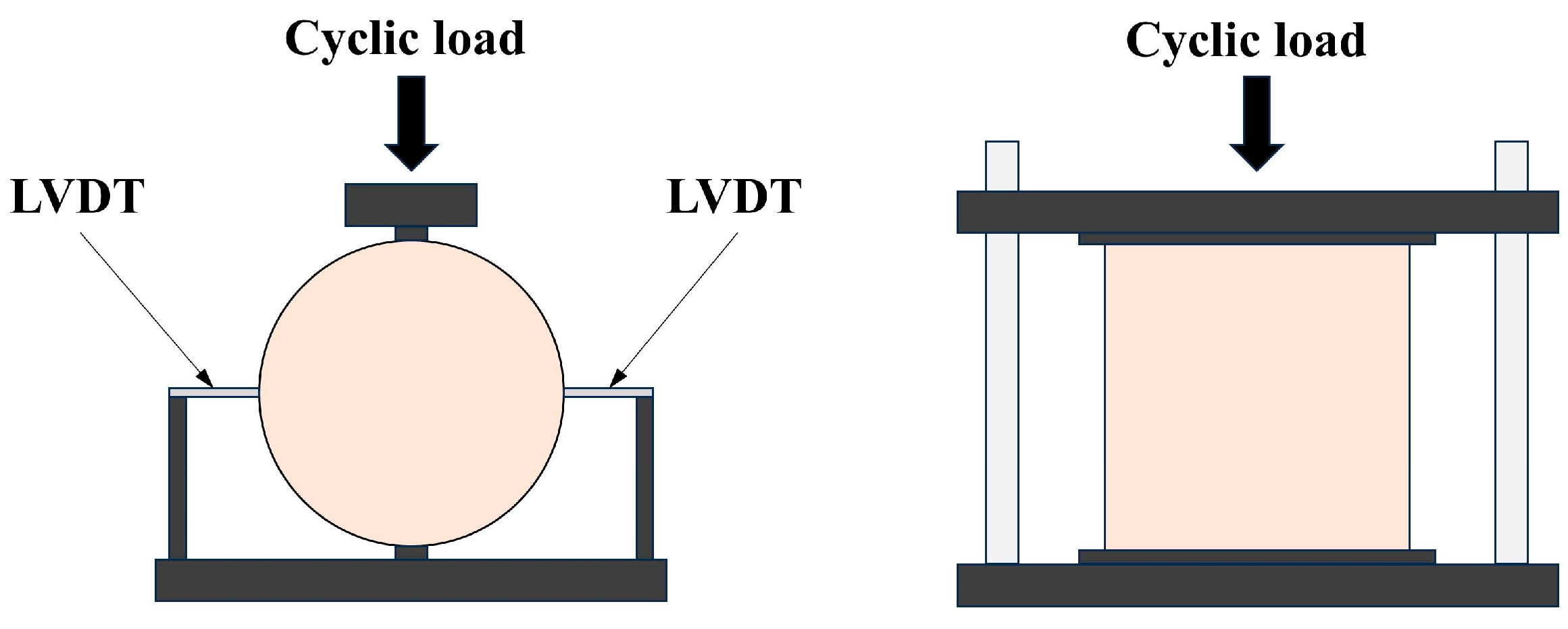
2.4. Indirect Tensile Fatigue Test
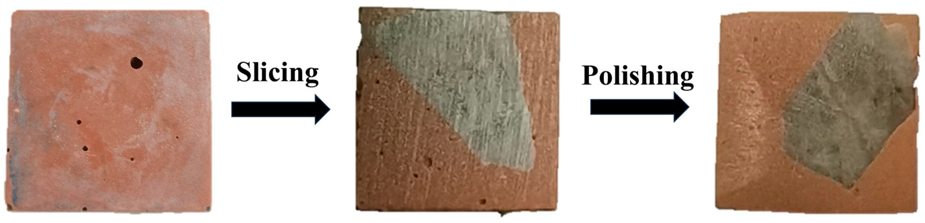
2.5. Microstructural Characterization Instrumentation Methods
3. Results and Discussions
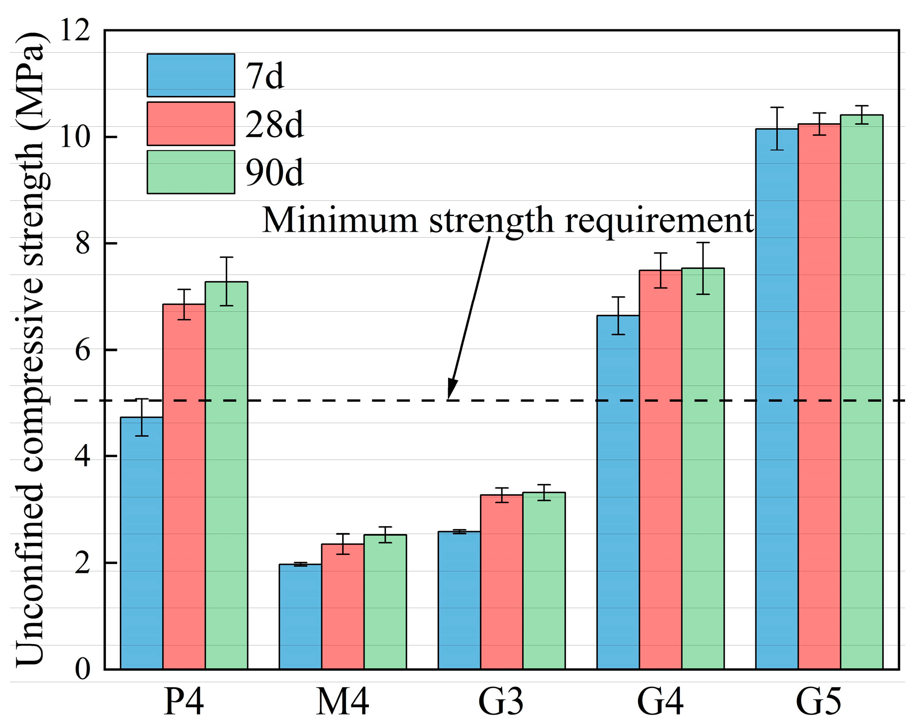
3.1. Compressive Strength
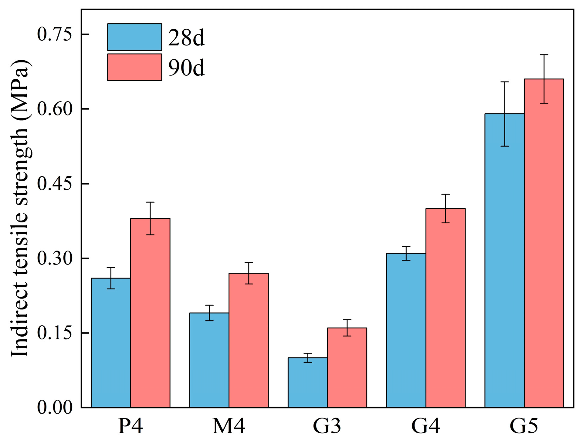
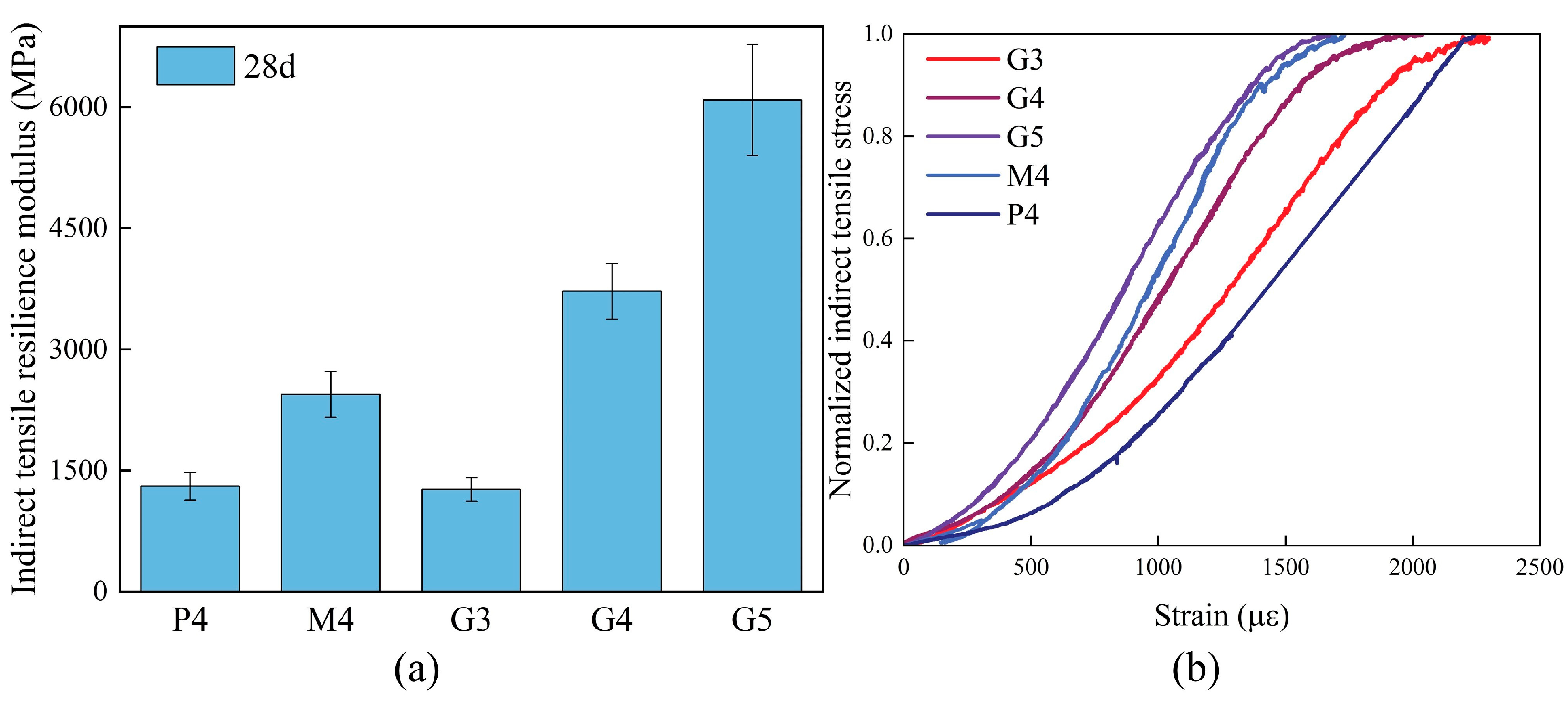
3.2. Indirect Tensile Fatigue
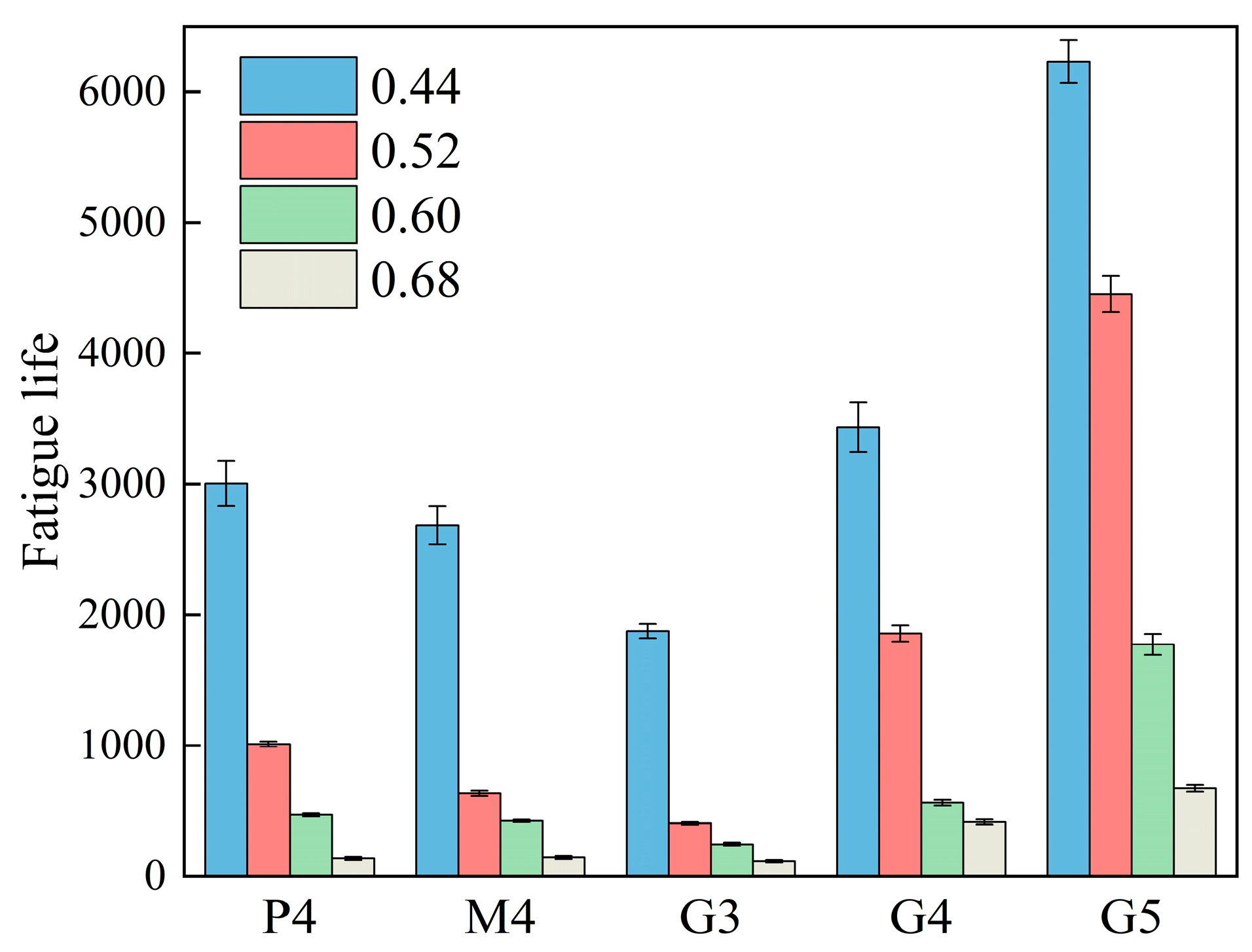
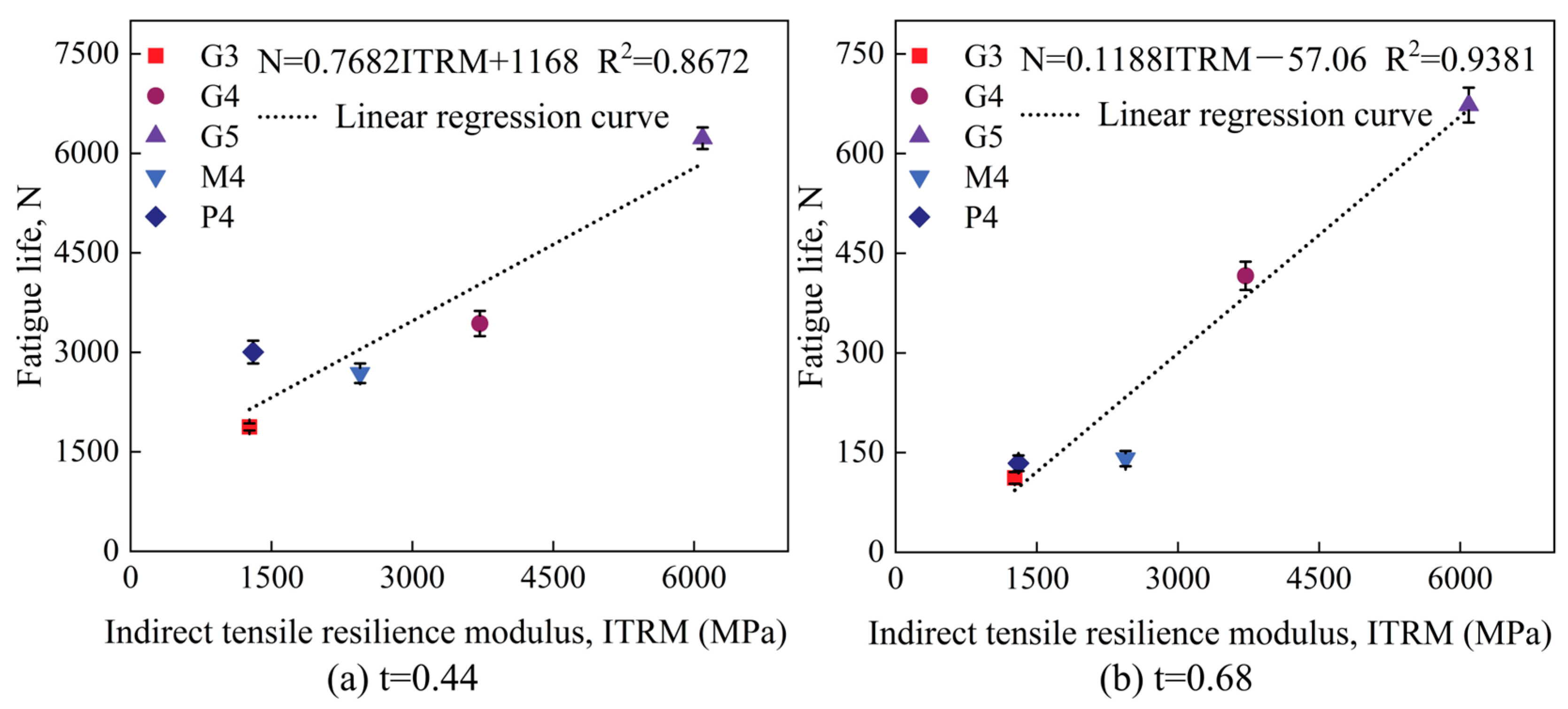
3.2.1. Indirect Tensile Fatigue Life
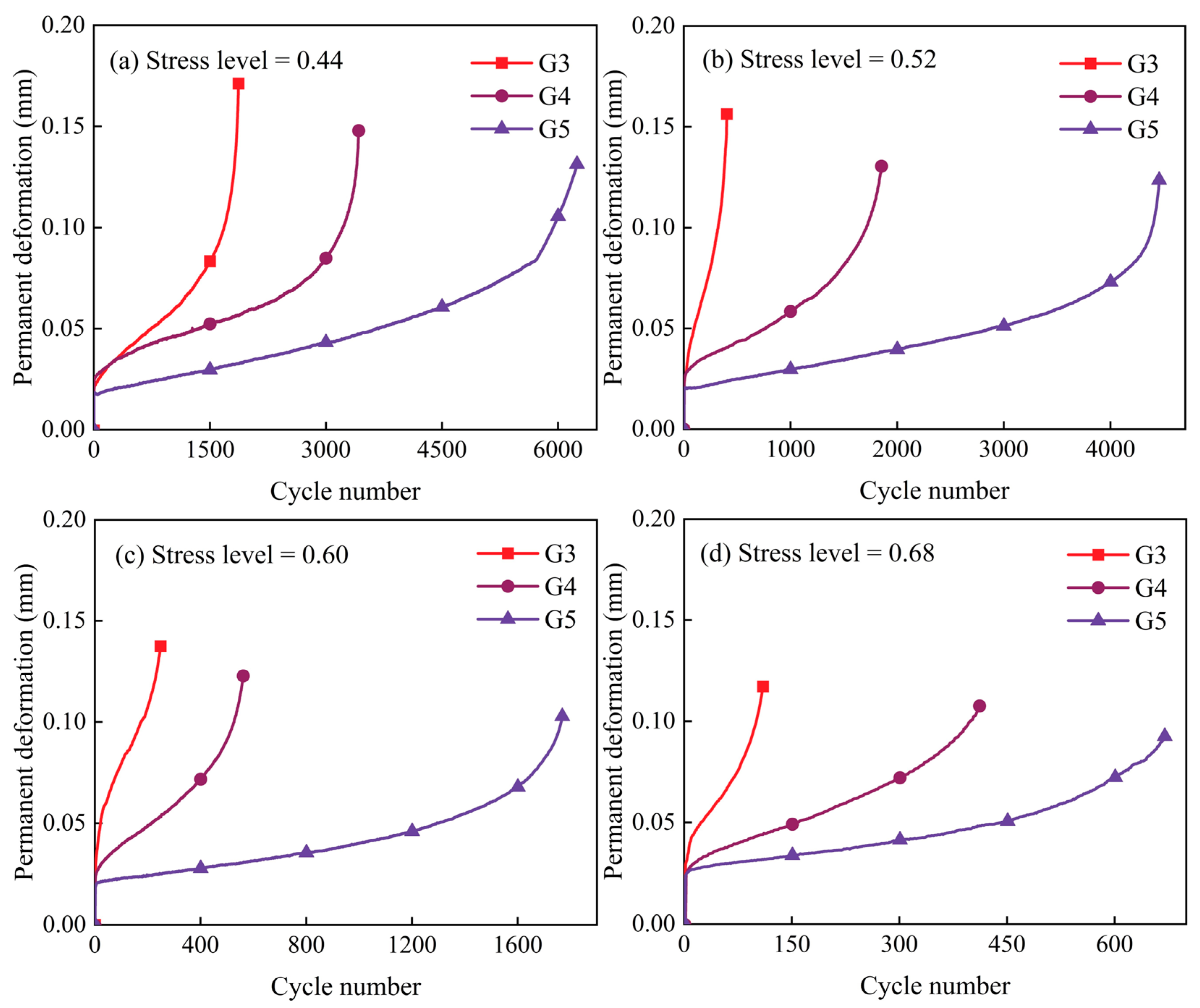
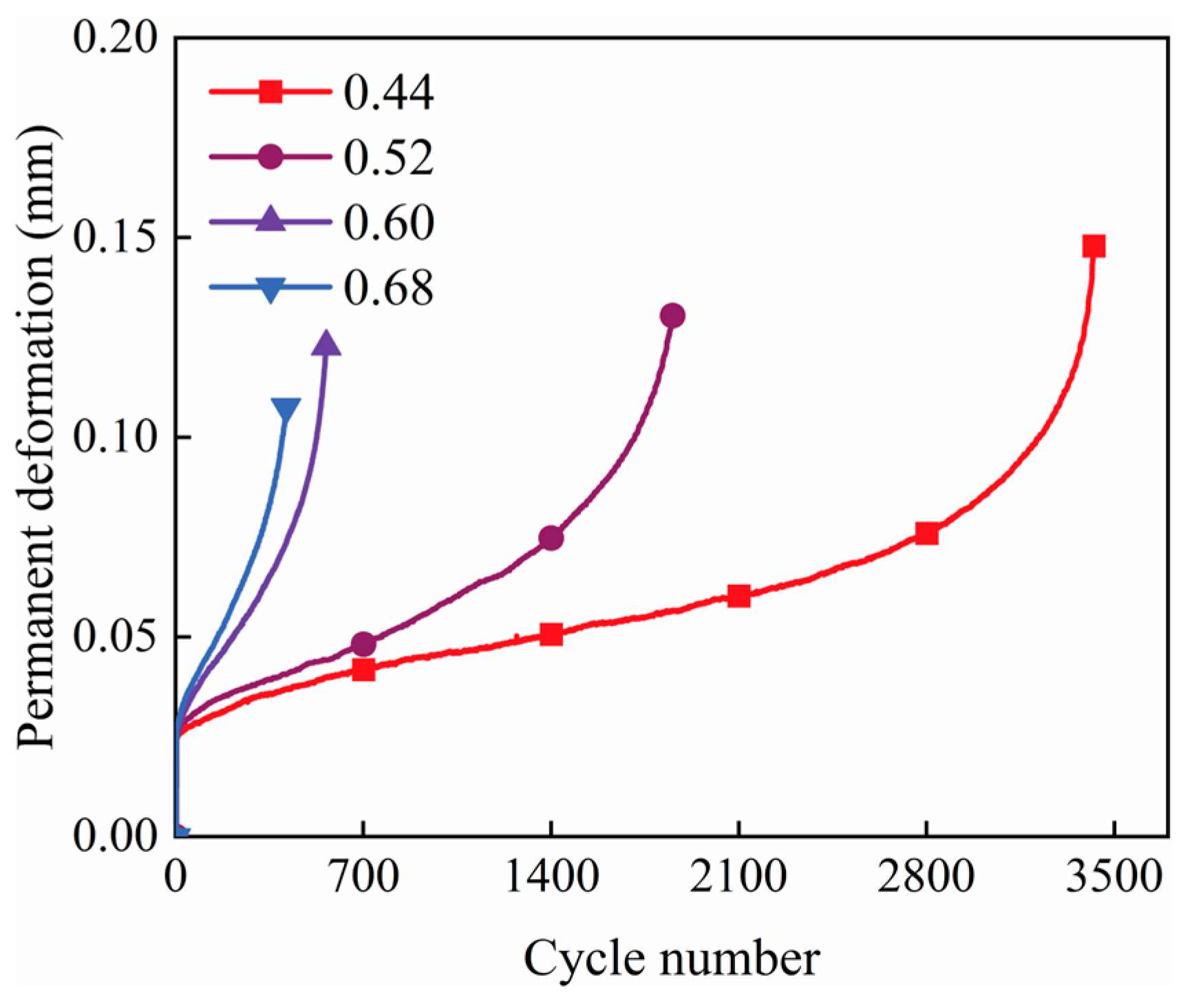
3.2.2. Deformation Characteristics During Fatigue Testing
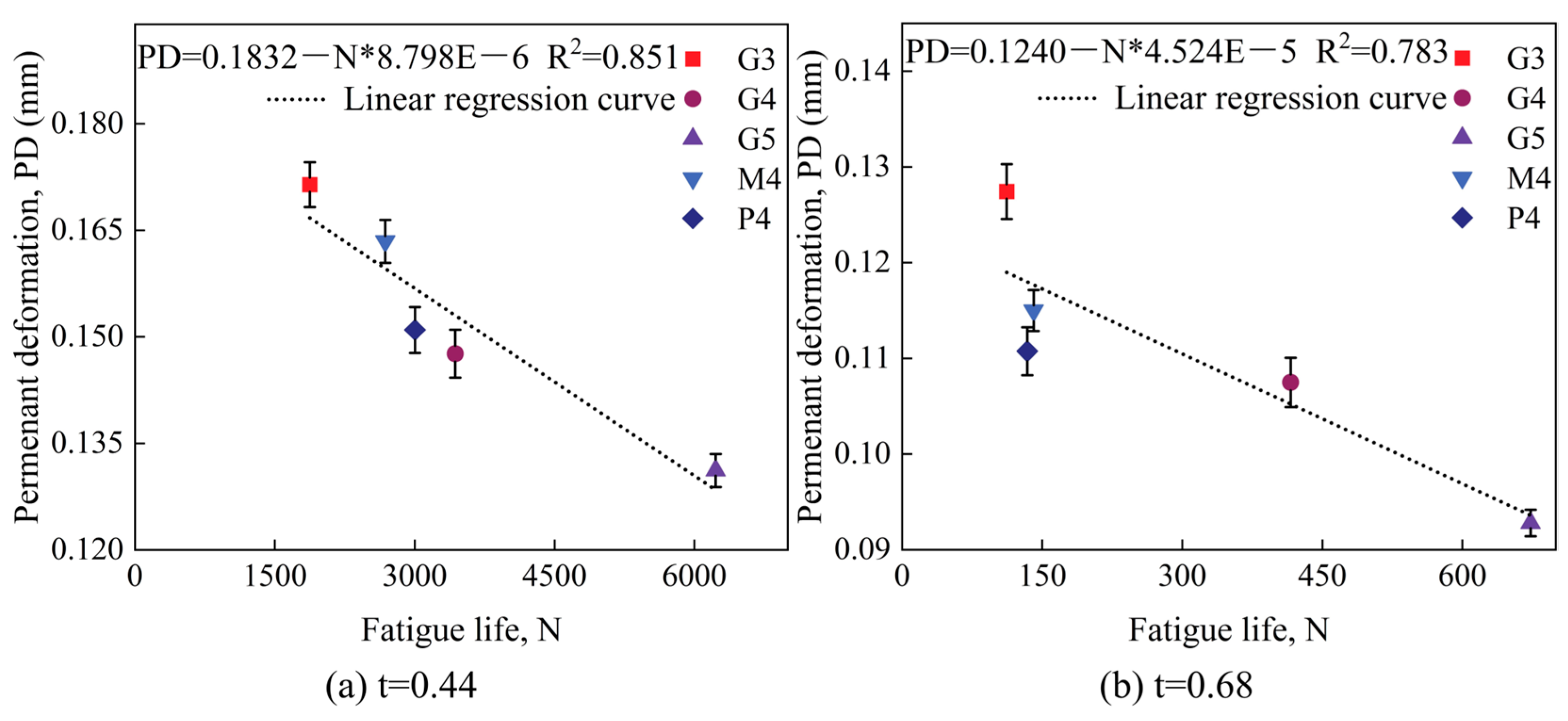
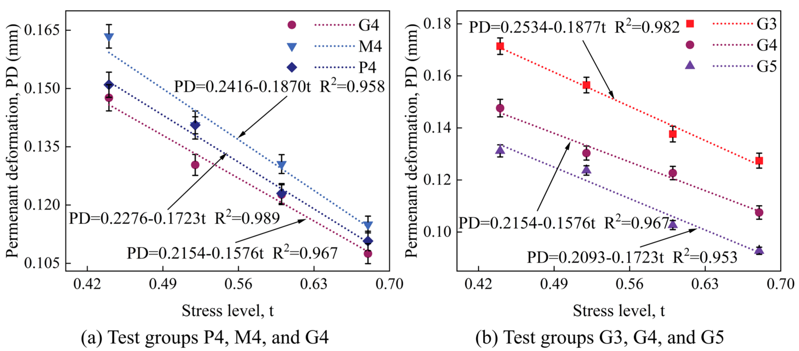
3.2.3. Permanent Deformation and Fatigue Model
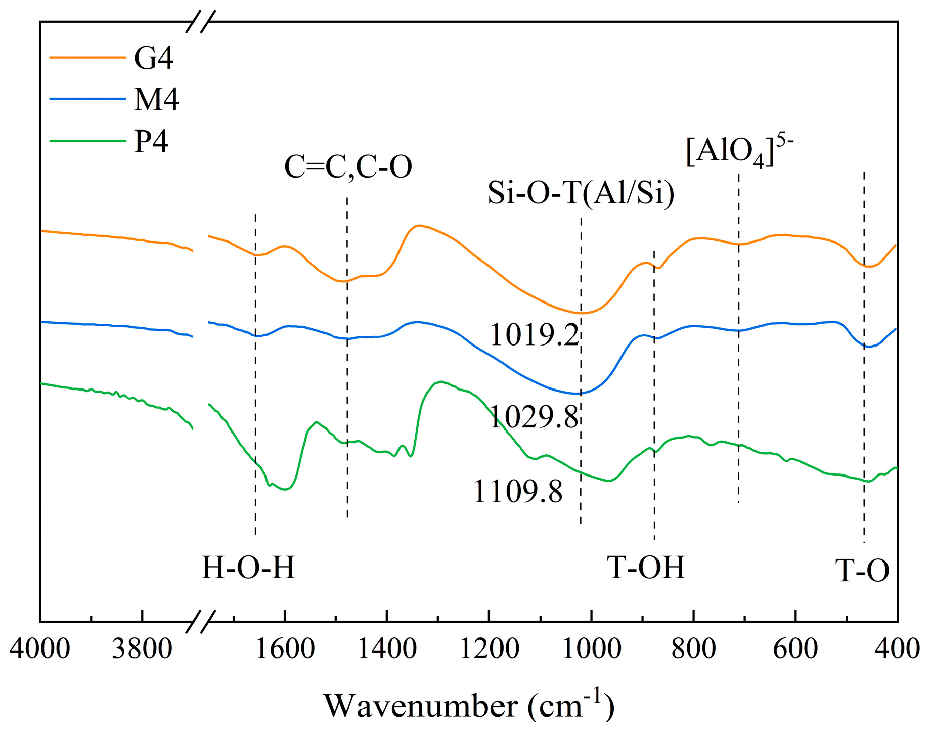
3.3. FTIR
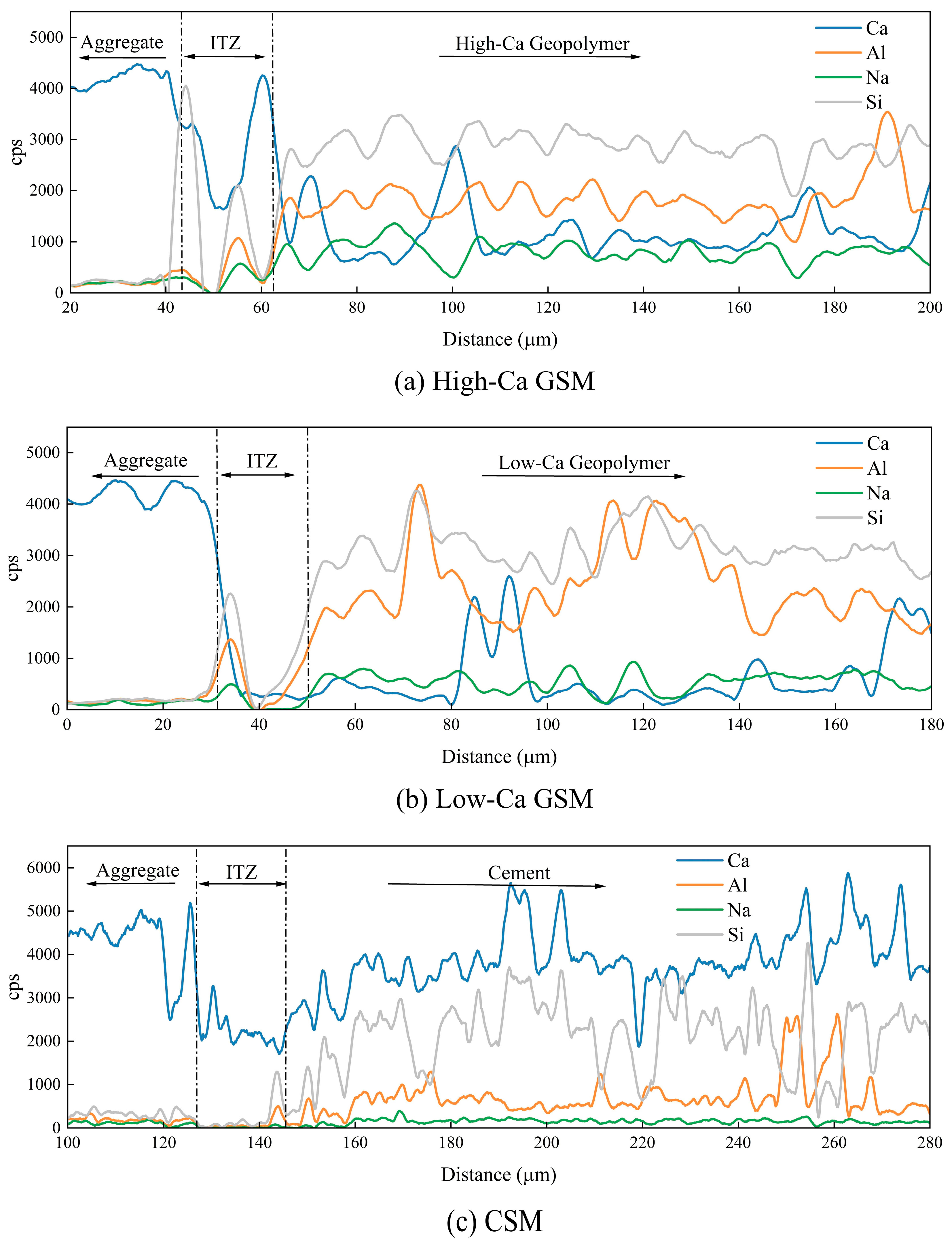
3.4. SEM and EDS
4. Conclusions
- The mechanical properties of high-Ca GSM significantly improve with an increase in the binder-to-aggregate ratio, as high-Ca GSM forms C–A–S–H gel, which promotes rapid strength development.
- High-Ca GSM exhibits the highest fatigue life and resistance to permanent deformation under cyclic loading, surpassing both CSM and low-Ca GSM. Increasing the binder-to-aggregate ratio further enhances the density of high-Ca GSM, thereby improving its fatigue life and resistance to cyclic loading-induced permanent deformation.
- FTIR tests find that high-Ca GSM dissolves more [AlO4]5− during the reaction compared with low-Ca GSM and CSM, resulting in the formation of more uniform gel and enhancing early strength development.
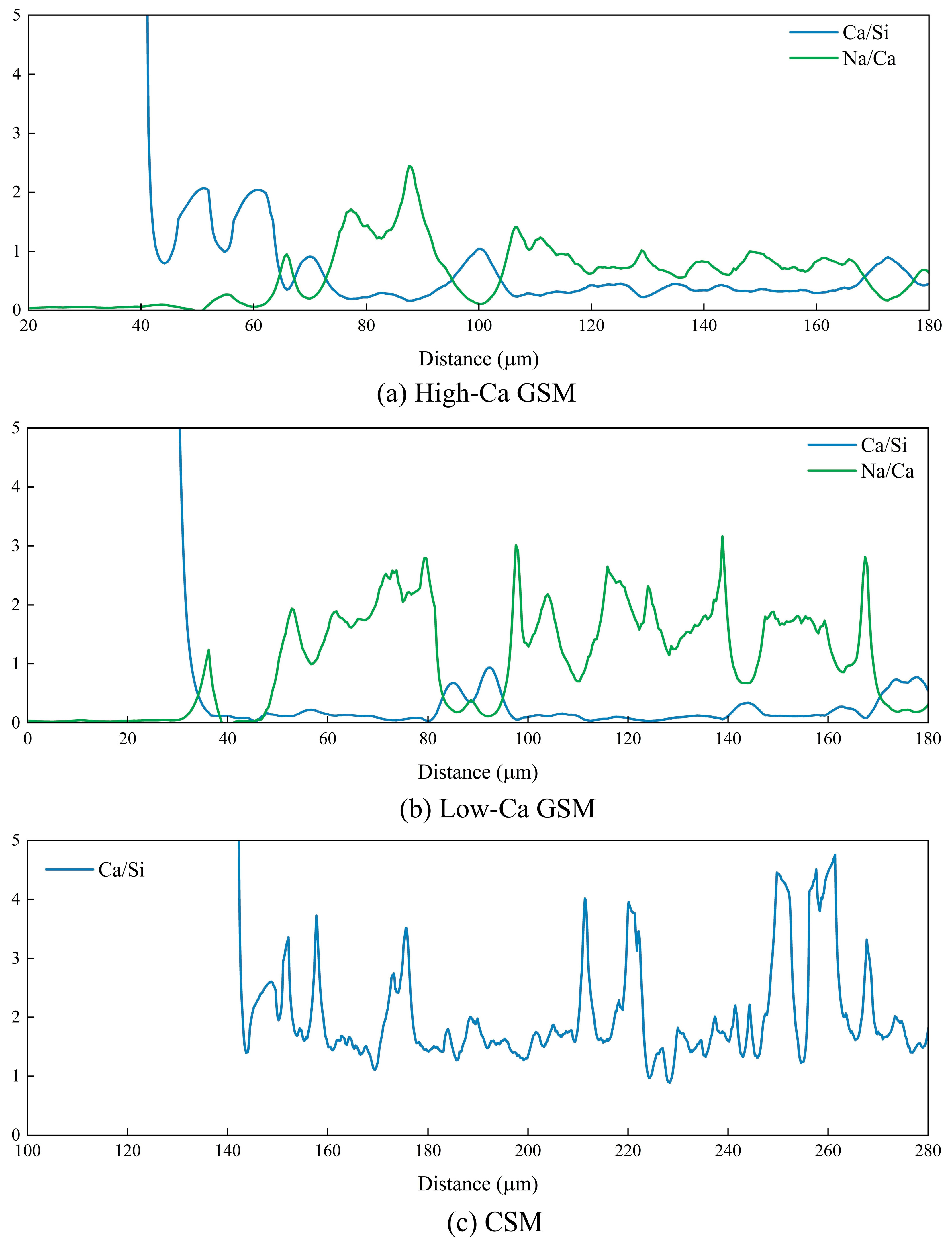
- SEM and EDS tests find that an aggregation of C(N)–A–S–H gel at the geopolymer-aggregate interface in high-Ca GSM, and the primary source of interface bonding strength is provided by mechanical interlocking in GSM and CSM.
Author Contributions
Funding
Institutional Review Board Statement
Informed Consent Statement
Data Availability Statement
Conflicts of Interest
References
- Sobhan, K.; BM, D. Durability of Soil–Cements against Fatigue Fracture. J. Mater. Civ. Eng. 2007, 19, 26–32. [Google Scholar] [CrossRef]
- Sounthararajah, A.; Hong Bui, H.; Nguyen, N.; Peerapong, J.; Jayantha, K. Early-Age Fatigue Damage Assessment of Cement-Treated Bases under Repetitive Heavy Traffic Loading. J. Mater. Civ. Eng. 2018, 30, 0002250. [Google Scholar] [CrossRef]
- Jitsangiam, P.; Nusit, K.; Chummuneerat, S.; Chindaprasirt, P.; Pichayapan, P. Fatigue Assessment of Cement-Treated Base for Roads: An Examination of Beam-Fatigue Tests. J. Mater. Civ. Eng. 2016, 28, 0001601. [Google Scholar] [CrossRef]
- Dan, H.-C.; Xie, P.; Shan, H.; Zhang, Z.; Cao, W. Investigation on the roller-pavement interaction and asphalt pavement compactness based on marginal spectrum of vibration signal energy. Constr. Build. Mater. 2024, 411, 134381. [Google Scholar] [CrossRef]
- Lv, S.; Xia, C.; Liu, H.; You, L.; Qu, F.; Zhong, W.; Yang, Y.; Washko, S. Strength and fatigue performance for cement-treated aggregate base materials. Int. J. Pavement Eng. 2019, 22, 690–699. [Google Scholar] [CrossRef]
- Zhao, X.; Dong, Q.; Yuan, J.; Chen, X.; Yang, J. Micro-scale characterization of the heterogeneous properties of in-service cement-treated base material. Constr. Build. Mater. 2020, 264, 120696. [Google Scholar] [CrossRef]
- Farhan, N.A.; Sheikh, M.N.; Hadi, M.N.S. Investigation of engineering properties of normal and high strength fly ash based geopolymer and alkali-activated slag concrete compared to ordinary Portland cement concrete. Constr. Build. Mater. 2019, 196, 26–42. [Google Scholar] [CrossRef]
- Huang, Y.; Huo, Z.; Ma, G.; Zhang, L.; Wang, F.; Zhang, J. Multi-objective optimization of fly ash-slag based geopolymer considering strength, cost and CO2 emission: A new framework based on tree-based ensemble models and NSGA-II. J. Build. Eng. 2023, 68, 106070. [Google Scholar] [CrossRef]
- Shi, J.; Liu, Y.; Wang, E.; Wang, L.; Li, C.; Xu, H.; Zheng, X.; Yuan, Q. Physico-mechanical, thermal properties and durability of foamed geopolymer concrete containing cenospheres. Constr. Build. Mater. 2022, 325, 126841. [Google Scholar] [CrossRef]
- Su, Y.; Luo, B.; Luo, Z.; Xu, F.; Huang, H.; Long, Z.; Shen, C. Mechanical characteristics and solidification mechanism of slag/fly ash-based geopolymer and cement solidified organic clay: A comparative study. J. Build. Eng. 2023, 71, 106459. [Google Scholar] [CrossRef]
- Zhou, X.; Zheng, K.; Chen, L.; Prateek, G.; Yuan, Q. An approach to improve the reactivity of basic oxygen furnace slag: Accelerated carbonation and the combined use of metakaolin. Constr. Build. Mater. 2023, 379, 131218. [Google Scholar] [CrossRef]
- Zhu, X.; Li, W.; Du, Z.; Zhou, S.; Zhang, Y.; Li, F. Recycling and utilization assessment of steel slag in metakaolin based geopolymer from steel slag by-product to green geopolymer. Constr. Build. Mater. 2021, 305, 124654. [Google Scholar] [CrossRef]
- Arulrajah, A.; Perera, S.; Wong, Y.C.; Maghool, F.; Horpibulsuk, S. Stabilization of PET plastic-demolition waste blends using fly ash and slag-based geopolymers in light traffic road bases/subbases. Constr. Build. Mater. 2021, 284, 122809. [Google Scholar] [CrossRef]
- Dan, H.; Ma, Z.; Li, M.; Ma, S.; Tan, J. Early performance and bonding mechanism of metakaolin (MK)-ground granulated blast furnace slag (GGBS) based geopolymer road repair mortar. Int. J. Pavement Eng. 2023, 24, 2252156. [Google Scholar] [CrossRef]
- Saranya, P.; Praveen, N.; Shashikala, A.P. Fracture properties of GGBS-dolomite geopolymer concrete. J. Eng. Des. Technol. 2021, 22, 120–129. [Google Scholar]
- Feng, B.; Lu, Z.; Zhang, Y.; Zhang, X.; He, L.; Li, Y. Physical, mechanical properties and microstructure of waste GBFS-based geopolymer incorporated with metakaolin and SiC whiskers(SiC). J. Build. Eng. 2024, 91, 109653. [Google Scholar] [CrossRef]
- Shi, S.; Wang, N.; Chen, C.; Ma, T.; Chen, F.; Gu, G. Multiscale study of the effect of fly ash geopolymer on the fatigue cracking of cement stabilized macadam. Constr. Build. Mater. 2023, 369, 130464. [Google Scholar] [CrossRef]
- Hamed, E.; Demiröz, A. Optimization of geotechnical characteristics of clayey soils using fly ash and granulated blast furnace slag-based geopolymer. Constr. Build. Mater. 2024, 441, 137488. [Google Scholar] [CrossRef]
- Zhou, S.; Yang, Z.; Zhang, R.; Li, F. Preparation, characterization and rheological analysis of eco-friendly road geopolymer grouting materials based on volcanic ash and metakaolin. J. Clean. Prod. 2021, 312, 127822. [Google Scholar] [CrossRef]
- Ma, Z.; Dan, H.; Tan, J.; Li, M.; Li, S. Optimization Design of MK-GGBS Based Geopolymer Repairing Mortar Based on Response Surface Methodology. Materials 2023, 16, 1889. [Google Scholar] [CrossRef]
- Du, S. Mechanical properties and shrinkage characteristics of cement stabilized macadam with asphalt emulsion. Constr. Build. Mater. 2019, 203, 408–416. [Google Scholar] [CrossRef]
- Lv, S.; Peng, X.; Yuan, J.; Liu, H.; Hu, L.; Yang, S.; Liu, J. Stress path investigation of fatigue characteristics of cement stabilized macadam. Constr. Build. Mater. 2021, 292, 123446. [Google Scholar] [CrossRef]
- Zheng, Y.; Zhang, P.; Cai, Y.; Jin, Z.; Moshtagh, E. Cracking resistance and mechanical properties of basalt fibers reinforced cement-stabilized macadam. Compos. Part B Eng. 2019, 165, 312–334. [Google Scholar] [CrossRef]
- Doan, T.; Arulrajah, A.; Lin, Y.; Horpibulsuk, S.; Chu, J.; Darmawan, S. Chemical stabilization of demolition wastes in pavement bases using one–part fly ash and slag based geopolymers. Transp. Geotech. 2024, 45, 101192. [Google Scholar] [CrossRef]
- Anburuvel, A.; Sathiparan, N.; Dhananjaya, G.M.A.; Anuruththan, A. Characteristic evaluation of geopolymer based lateritic soil stabilization enriched with eggshell ash and rice husk ash for road construction: An experimental investigation. Constr. Build. Mater. 2023, 387, 131659. [Google Scholar] [CrossRef]
- Kavussi, A.; Modarres, A. Laboratory fatigue models for recycled mixes with bitumen emulsion and cement. Constr. Build. Mater. 2010, 24, 1920–1927. [Google Scholar] [CrossRef]
- Hoy, M.; Tran, N.Q.; Suddeepong, A.; Horpibulsuk, S.; Mobkrathok, M.; Chinkulkijniwat, A.; Arulrajah, A. Improved fatigue properties of cement-stabilized recycled materials—Lateritic soil using natural rubber latex for sustainable pavement applications. Transp. Geotech. 2023, 40, 100959. [Google Scholar] [CrossRef]
- Ministry of Transport. Test Methods of Aggregate for Highway Engineerimg; People’s Communications Press: Beijing, China, 2005. [Google Scholar]
- Ministry of Transport. Technical Guidelines for Construction of Highway Roadbases; People’s Communications Press: Beijing, China, 2015. [Google Scholar]
- Ministry of Transport. Test Methods of Materials Stabilized with Inorganic Binders for Highway Engineering; People’s Communications Press: Beijing, China, 2009. [Google Scholar]
- Gnanendran, C.T.; Piratheepan, J. Characterisation of a lightly stabilised granular material by indirect diametrical tensile testing. Int. J. Pavement Eng. 2008, 9, 445–456. [Google Scholar] [CrossRef]
- Piratheepan, J.; Gnanendran, C.; Lo, S. Characterization of Cementitiously Stabilized Granular Materials for Pavement Design Using Unconfined Compression and IDT Testings with Internal Displacement Measurements. J. Mater. Civ. Eng. 2010, 22, 495–505. [Google Scholar] [CrossRef]
- Dan, H.-C.; Ling, C.; Cao, W.; Wang, Z.; Liu, J. Fatigue behavior and phenomenological modeling of porous asphalt concrete under freeze–thaw cycling. Mater. Struct. 2021, 54, 235. [Google Scholar] [CrossRef]
- Dan, H.-C.; Wang, Z.; Cao, W.; Liu, J. Fatigue characterization of porous asphalt mixture complicated with moisture damage. Constr. Build. Mater. 2021, 303, 124525. [Google Scholar] [CrossRef]
- BS-EN-12697-24; Bituminous Mixtures—Test Methods for Hot Mix Asphalt; British Standards Institution: London, UK, 2012.
- Bao, H.; Xu, G.; Yu, M.; Wang, Q.; Li, R.; Saafi, M.; Ye, J. Evolution of ITZ and its effect on the carbonation depth of concrete under supercritical CO2 condition. Cem. Concr. Compos. 2022, 126, 104336. [Google Scholar] [CrossRef]
- Arulrajah, A.; Perera, S.; Wong, Y.C.; Horpibulsuk, S.; Maghool, F. Stiffness and flexural strength evaluation of cement stabilized PET blends with demolition wastes. Constr. Build. Mater. 2020, 239, 117819. [Google Scholar] [CrossRef]
- Disfani, M.M.; Arulrajah, A.; Haghighi, H.; Mohammadinia, A.; Horpibulsuk, S. Flexural beam fatigue strength evaluation of crushed brick as a supplementary material in cement stabilized recycled concrete aggregates. Constr. Build. Mater. 2014, 68, 667–676. [Google Scholar] [CrossRef]
- Festugato, L.; Venson, G.I.; Consoli, N.C. Parameters controlling cyclic behaviour of cement-treated sand. Transp. Geotech. 2021, 27, 100488. [Google Scholar] [CrossRef]
- Lecomte, J.; Liégeois, M.; Rulmont, A.; Cloots, R. Synthesisand characterization of new inorganic polymeric compositesbased on kaolin or white clay and on ground granulated blastfurnace slag. J. Mater. Res. 2003, 18, 2571–2579. [Google Scholar] [CrossRef]
- Luo, Y.; Wu, H.; Song, W.; Yin, J.; Zhan, Y.; Yu, J.; Abubakar Wada, S. Thermal fatigue and cracking behaviors of asphalt mixtures under different temperature variations. Constr. Build. Mater. 2023, 369, 130623. [Google Scholar] [CrossRef]
- Wu, H.; Huang, K.; Song, W.; He, F. Characterizing the fatigue cracking behaviors of OGFC pavements using the overlay tester. Constr. Build. Mater. 2021, 307, 124979. [Google Scholar] [CrossRef]
- Zhang, J.; Rao, Q.; Yi, W. A New Creep-Fatigue Interaction Model for Predicting Deformation of Coarse-Grained Soil. Materials 2022, 15, 3904. [Google Scholar] [CrossRef] [PubMed]
- Zhou, X.; Song, W.; Wu, H. Investigation on Fracture Performance of Hot-Mix Asphalt with Reclaimed Asphalt Pavement under Fatigue Loading. Coatings 2023, 13, 1318. [Google Scholar] [CrossRef]
- Khedr, S. Deformation characteristics of granular base course in flexible pavements. Trans. Res. Rec. 1985, 1043, 131–138. [Google Scholar]
- Castañeda López, M.A.; Fedrigo, W.; Kleinert, T.R.; Matuella, M.F.; Núñez, W.P.; Ceratti, J.A.P. Flexural fatigue evaluation of cement-treated mixtures of reclaimed asphalt pavement and crushed aggregates. Constr. Build. Mater. 2018, 158, 320–325. [Google Scholar] [CrossRef]
- Criado, M.; Palomo, A.; Fernandezjimenez, A. Alkali activation of fly ashes. Part 1: Effect of curing conditions on the carbonation of the reaction products. Fuel 2005, 84, 2048–2054. [Google Scholar] [CrossRef]
- Zarzuela, R.; Luna, M.; Carrascosa, L.M.; Yeste, M.P.; Garcia-Lodeiro, I.; Blanco-Varela, M.T.; Cauqui, M.A.; Rodríguez-Izquierdo, J.M.; Mosquera, M.J. Producing C-S-H gel by reaction between silica oligomers and portlandite: A promising approach to repair cementitious materials. Cem. Concr. Res. 2020, 130, 106008. [Google Scholar] [CrossRef]
- Zhang, Y.; Sun, W.; Li, Z. Infrared spectroscopy study of structural nature of geopolymeric products. J. Wuhan Univ. Technol. Mater. Sci. Ed. 2008, 23, 522–527. [Google Scholar] [CrossRef]
- Hajimohammadi, A.; Provis, J.L.; van Deventer, J.S.J. Effect of Alumina Release Rate on the Mechanism of Geopolymer Gel Formation. Chem. Mater. 2010, 22, 5199–5208. [Google Scholar] [CrossRef]
- Myers, R.J.; Bernal, S.A.; Provis, J.L. Phase diagrams for alkali-activated slag binders. Cem. Concr. Res. 2017, 95, 30–38. [Google Scholar] [CrossRef]
- Wang, Y.-S.; Peng, K.-D.; Alrefaei, Y.; Dai, J.-G. The bond between geopolymer repair mortars and OPC concrete substrate: Strength and microscopic interactions. Cem. Concr. Compos. 2021, 119, 103991. [Google Scholar] [CrossRef]
- Singh, N.B.; Middendorf, B. Geopolymers as an alternative to Portland cement: An overview. Constr. Build. Mater. 2020, 237, 117455. [Google Scholar] [CrossRef]
- Zhou, H.-Y.; Wang, X.-S.; Hu, X.-X.; Xiong, Z.-Q.; Zhang, X.-Y. Influencing factors and mechanism analysis of strength development of geopolymer stabilized sludge. Rock Soil Mech. 2021, 42, 2089–2098. [Google Scholar]
- Li, C.; Sun, H.; Li, L. A review: The comparison between alkali-activated slag (Si + Ca) and metakaolin (Si + Al) cements. Cem. Concr. Res. 2010, 40, 1341–1349. [Google Scholar] [CrossRef]
- Ismail, I.; Bernal, S.A.; Provis, J.L.; San Nicolas, R.; Hamdan, S.; van Deventer, J.S.J. Modification of phase evolution in alkali-activated blast furnace slag by the incorporation of fly ash. Cem. Concr. Compos. 2014, 45, 125–135. [Google Scholar] [CrossRef]
- Tan, J.; Cizer, Ö.; Vandevyvere, B.; De Vlieger, J.; Dan, H.; Li, J. Efflorescence mitigation in construction and demolition waste (CDW) based geopolymer. J. Build. Eng. 2022, 58, 105001. [Google Scholar] [CrossRef]
- Zhu, H.; Liang, G.; Li, H.; Wu, Q.; Zhang, C.; Yin, Z.; Hua, S. Insights to the sulfate resistance and microstructures of alkali-activated metakaolin/slag pastes. Appl. Clay Sci. 2021, 202, 105968. [Google Scholar] [CrossRef]
- Dan, H.; Li, M.; Tan, J.; Dan, H.; Ma, Z.; Ma, S. Nano- and microscale characterization for interfacial transition zone of geopolymer stabilized recycled aggregate of asphalt pavement. Constr. Build. Mater. 2023, 397, 132368. [Google Scholar] [CrossRef]


| Oxides | SiO2 | Al2O3 | Fe2O3 | CaO | MgO | K2O | SO3 | Na2O | LOI * |
|---|---|---|---|---|---|---|---|---|---|
| MK | 61.8 | 32.5 | 0.8 | 0.2 | 2.1 | 0.6 | 0.1 | 0.1 | 1.8 |
| GGBS | 35.3 | 11.9 | 0.4 | 37.8 | 6.9 | 0.6 | 0.1 | 0.3 | 0.1 |
| Property | Coarse Aggregate Size > 9.5 mm | Fine Aggregate Size < 9.5 mm | Test Methods [28] |
|---|---|---|---|
| Percentage content of needle and flake particles (%) | 12.1 | - | T 0312 |
| Water absorption (%) | 1.25 | 1.98 | T 0307/T 0330 |
| Specific gravity by volume (g/cm3) | 1.50 | 1.49 | T 0309/T 0331 |
| Crushing value (%) | 10.3 | - | T 0316 |
| Percentage content of needle and flake particles (%) | 12.1 | - | T 0312 |
| Mixture ID | P4 | M4 | G3 | G4 | G5 |
|---|---|---|---|---|---|
| OPC (%) | 100 | 0 | 0 | 0 | 0 |
| GGBS (%) | 0 | 40 | 60 | 60 | 60 |
| MK (%) | 0 | 60 | 40 | 40 | 40 |
| Binder to aggregate ratio | 0.04 | 0.04 | 0.03 | 0.04 | 0.05 |
| Optimum moisture content (%) | 5.23 | 5.73 | 4.83 | 4.91 | 4.98 |
| Maximum dry density (g/cm3) | 2.366 | 2.356 | 2.346 | 2.388 | 2.422 |
Disclaimer/Publisher’s Note: The statements, opinions and data contained in all publications are solely those of the individual author(s) and contributor(s) and not of MDPI and/or the editor(s). MDPI and/or the editor(s) disclaim responsibility for any injury to people or property resulting from any ideas, methods, instructions or products referred to in the content. |
© 2025 by the authors. Licensee MDPI, Basel, Switzerland. This article is an open access article distributed under the terms and conditions of the Creative Commons Attribution (CC BY) license (https://creativecommons.org/licenses/by/4.0/).
Share and Cite
Dan, H.; Ma, S.; Li, M.; Tan, J.; Zhang, H. Experimental Investigation on Macroscopic and Microscopic Mechanical Properties of Geopolymer-Stabilized Macadam. Materials 2025, 18, 454. https://doi.org/10.3390/ma18020454
Dan H, Ma S, Li M, Tan J, Zhang H. Experimental Investigation on Macroscopic and Microscopic Mechanical Properties of Geopolymer-Stabilized Macadam. Materials. 2025; 18(2):454. https://doi.org/10.3390/ma18020454
Chicago/Turabian StyleDan, Hancheng, Shenglong Ma, Mengjin Li, Jiawei Tan, and Haoran Zhang. 2025. "Experimental Investigation on Macroscopic and Microscopic Mechanical Properties of Geopolymer-Stabilized Macadam" Materials 18, no. 2: 454. https://doi.org/10.3390/ma18020454
APA StyleDan, H., Ma, S., Li, M., Tan, J., & Zhang, H. (2025). Experimental Investigation on Macroscopic and Microscopic Mechanical Properties of Geopolymer-Stabilized Macadam. Materials, 18(2), 454. https://doi.org/10.3390/ma18020454