
Fabrication and Compression Properties of Two-Layered Porous Structure of Different Materials by Direct Printing of Resin Porous Structure on Aluminum Foam Using a 3D Printer


Abstract
1. Introduction
2. Materials and Methods
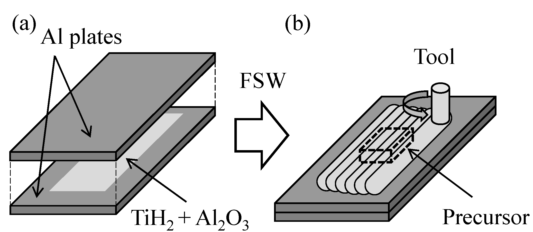
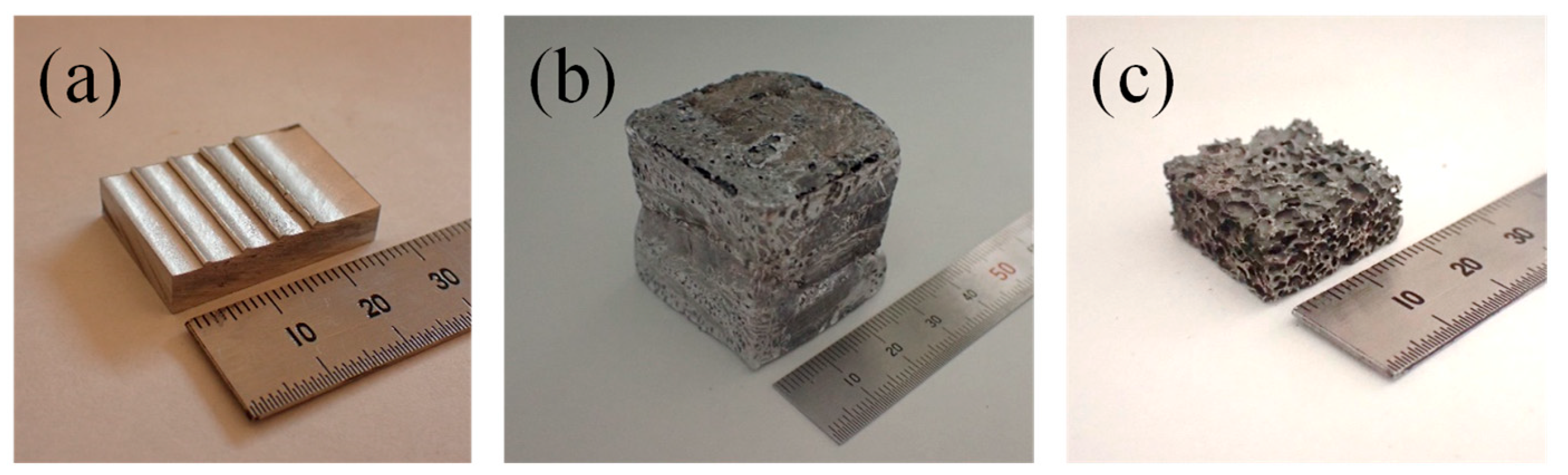
2.1. Fabrication of Aluminum Foam
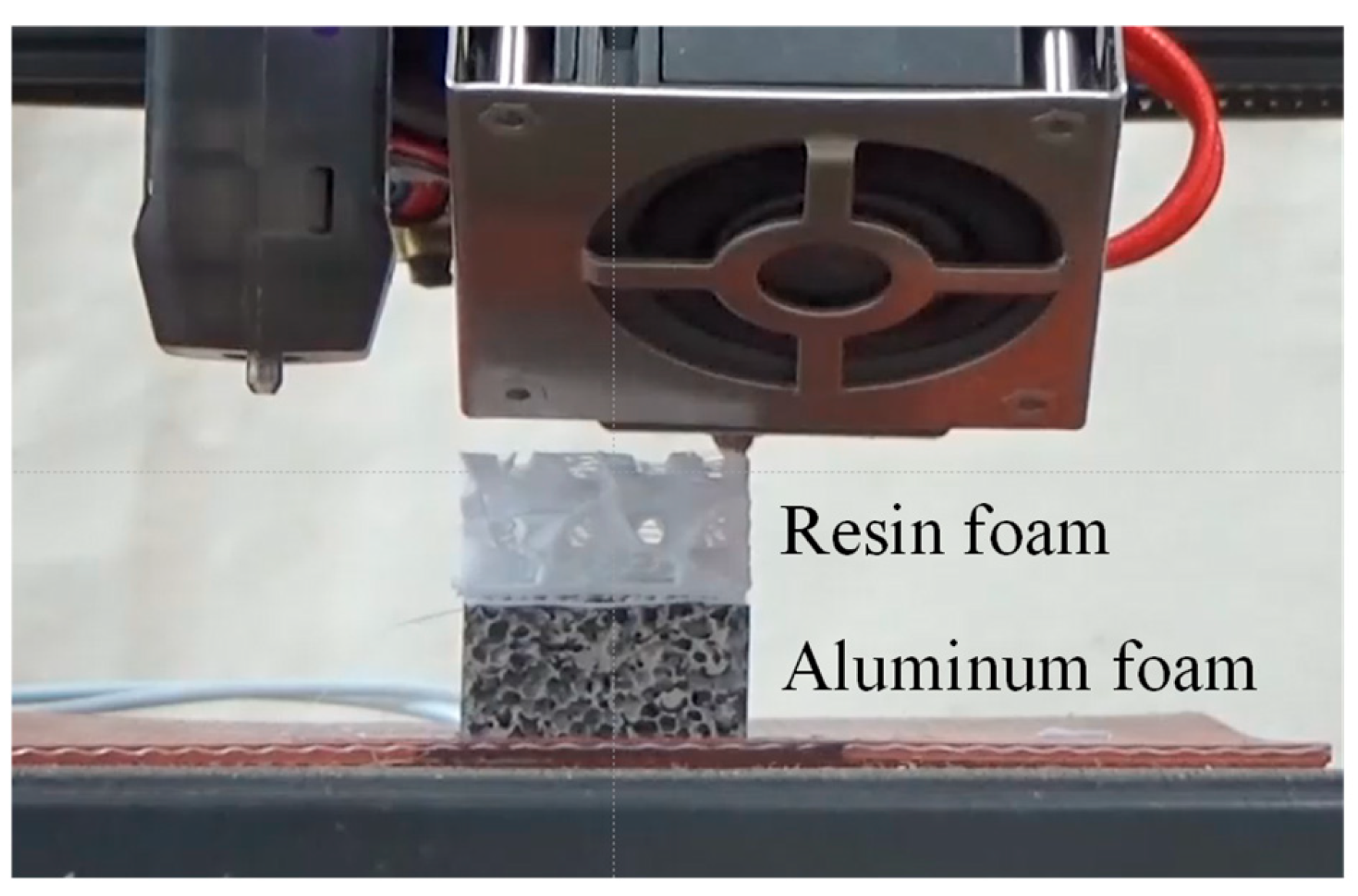
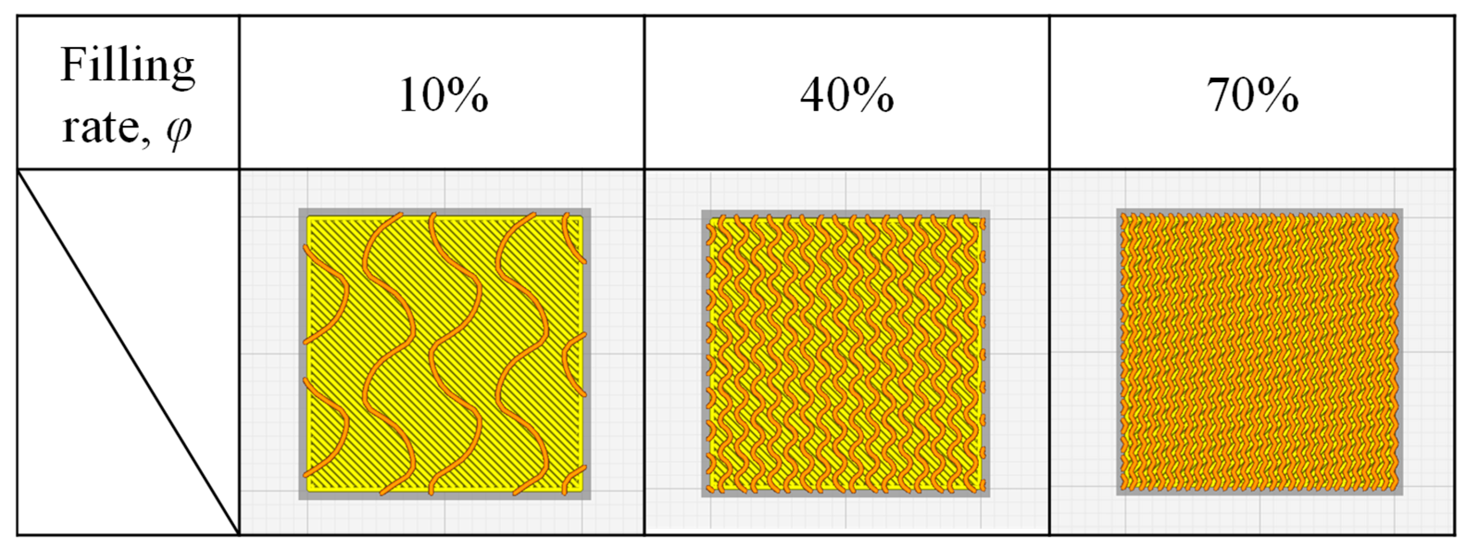
2.2. Resin Printing on Aluminum Foam
2.3. Compression Test
3. Results and Discussion
3.1. Obtained Compression Test Specimen
3.2. Compression Test Results of Uniform Resin Porous Structure
3.3. Compression Test Results of Two-Layered Porous Structure
3.4. Plateau Stress Estimation Method for Two-Layered Porous Structure
4. Conclusions
- (1)
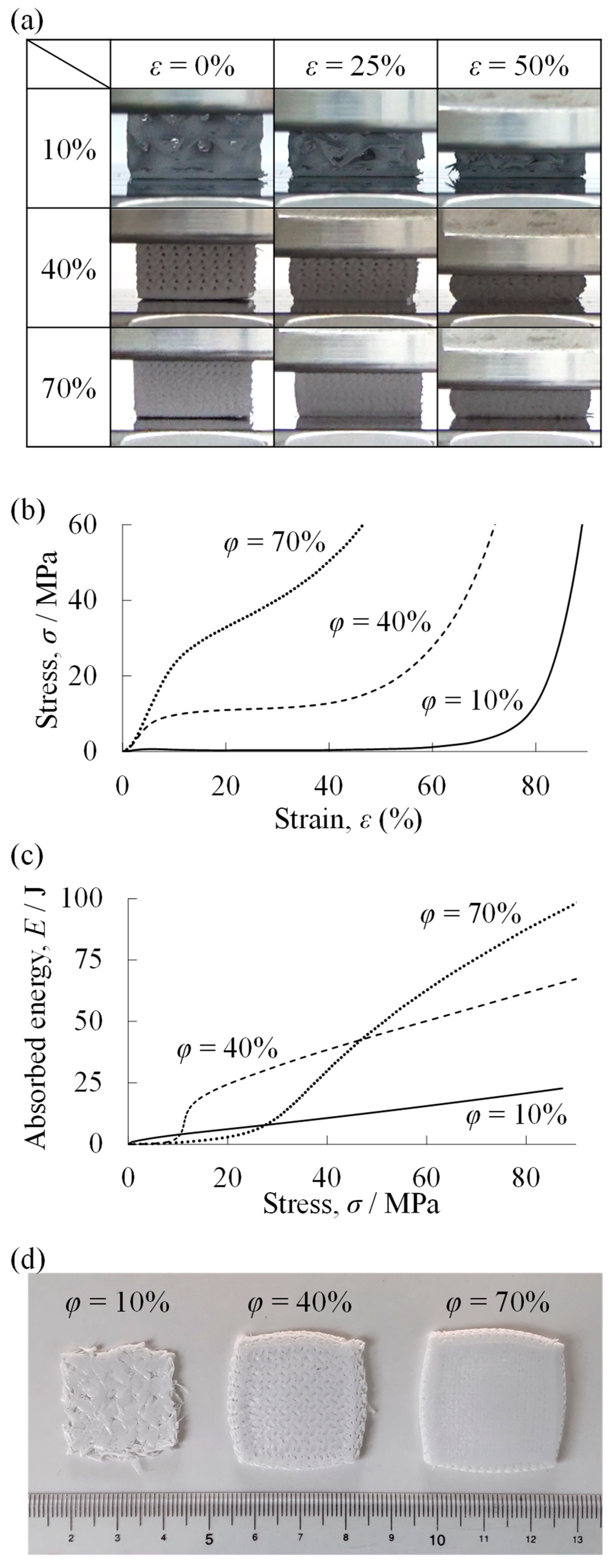
- In the uniform specimen of the resin porous structure fabricated by the 3D printer, three regions appeared: an elastic region, a plateau region, and a densification region, just as in conventional foams. The plateau stress increased as the resin filling rate φ of the uniform specimen of the resin porous structure increased, indicating that the specimen became higher in strength. The resin porous structure with small φ absorbed the maximum energy at low stress, while the resin porous structure with large φ absorbed the maximum energy at high stress. That is, the compression properties can be controlled by varying the resin filling rate of the uniform resin porous structure.
- (2)
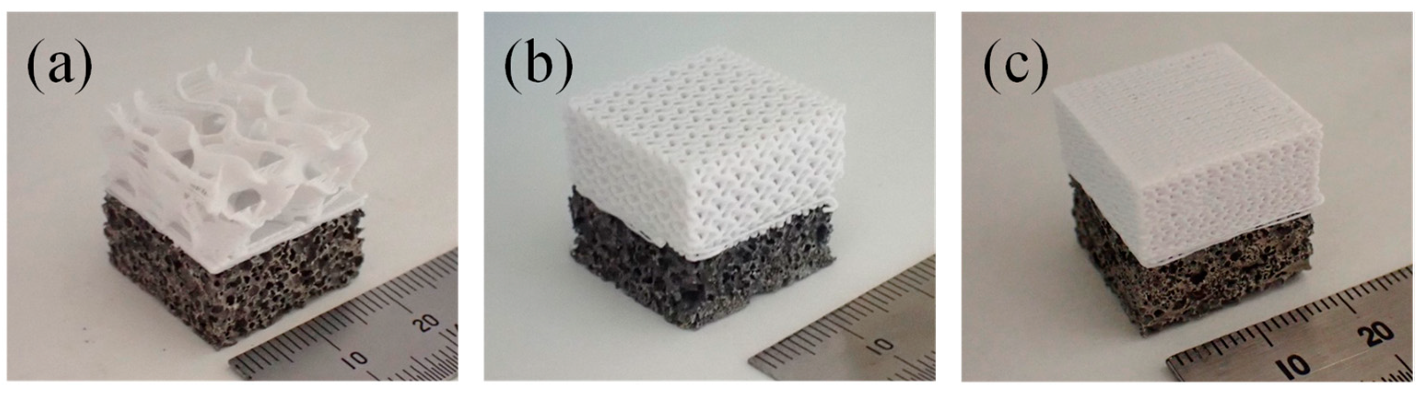
- The fabricated two-layered porous structure was effectively bonded between the two layers by the anchor effect, and no separation occurred. That is, it was found that a two-layered porous structure, in which the aluminum foam and the resin porous structure were combined, can be fabricated by directly printing the resin porous structure on the aluminum foam fabricated by the precursor method using a 3D printer.
- (3)
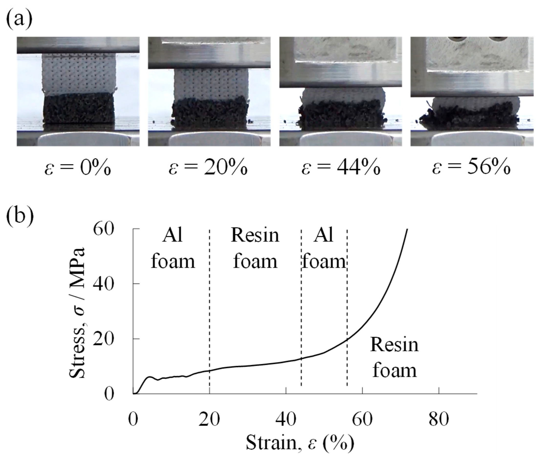
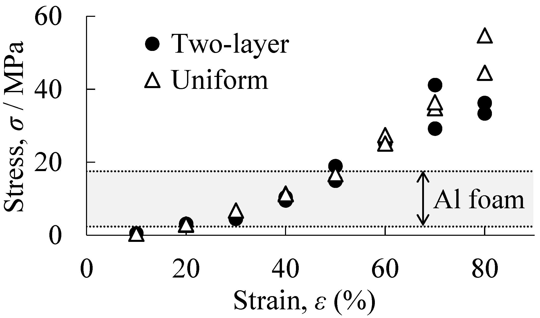
- By fabricating a two-layered structure consisting of aluminum foam and a resin porous structure, it was possible to fabricate a porous structure that exhibited both properties of aluminum foam and those of a resin porous structure. It was found that the deformation behavior and energy absorption properties of the two-layered porous structure can be controlled by varying the resin filling rate of the resin porous structure layer. That is, it was indicated that multi-layered porous structures with various densities and consisting of various types of materials allow for the optimal design of porous structures used in structural materials.
Author Contributions
Funding
Institutional Review Board Statement
Informed Consent Statement
Data Availability Statement
Conflicts of Interest
References
- Banhart, J. Light-Metal Foams—History of Innovation and Technological Challenges. Adv. Eng. Mater. 2013, 15, 82–111. [Google Scholar] [CrossRef]
- García-Moreno, F. Commercial applications of metal foams: Their properties and production. Materials 2016, 9, 85. [Google Scholar] [CrossRef] [PubMed]
- Kitazono, K.; Tada, R.; Sugiyama, Y.; Miura, T. Impact Energy Absorbing System for Space Lander Using Hemispherical Open-Cell Porous Aluminum. Mater. Sci. Forum 2018, 933, 337–341. [Google Scholar] [CrossRef]
- Kitazono, K.; Matsuo, K.; Hamaguchi, T.; Fujimori, Y. Design of Energy-Absorbing Materials for Space Crafts Based on Voronoi Diagrams. In Proceedings of the 11th International Conference on Porous Metals and Metallic Foams (MetFoam 2019), Dearborn, MI, USA, 20–23 August 2019; pp. 3–10. [Google Scholar] [CrossRef]
- Wan, T.; Liu, Y.; Zhou, C.; Chen, X.; Li, Y. Fabrication, properties, and applications of open-cell aluminum foams: A review. J. Mater. Sci. Technol. 2021, 62, 11–24. [Google Scholar] [CrossRef]
- Ji, C.; Huang, H.; Wang, T.; Huang, Q. Recent advances and future trends in processing methods and characterization technologies of aluminum foam composite structures: A review. J. Manuf. Process. 2023, 93, 116–152. [Google Scholar] [CrossRef]
- Fu, W.; Li, Y. Fabrication, Processing, Properties, and Applications of Closed-Cell Aluminum Foams: A Review. Materials 2024, 17, 560. [Google Scholar] [CrossRef]
- Baroutaji, A.; Sajjia, M.; Olabi, A.-G. On the crashworthiness performance of thin-walled energy absorbers: Recent advances and future developments. Thin-Walled Struct. 2017, 118, 137–163. [Google Scholar] [CrossRef]
- Xu, F.; Zhang, X.; Zhang, H. A review on functionally graded structures and materials for energy absorption. Eng. Struct. 2018, 171, 309–325. [Google Scholar] [CrossRef]
- Chen, D.; Gao, K.; Yang, J.; Zhang, L. Functionally graded porous structures: Analyses, performances, and applications—A Review. Thin-Walled Struct. 2023, 191, 111046. [Google Scholar] [CrossRef]
- Miyoshi, T.; Itoh, M.; Akiyama, S.; Kitahara, A. ALPORAS aluminum foam: Production process, properties, and applications. Adv. Eng. Mater. 2000, 2, 179–183. [Google Scholar] [CrossRef]
- Atwater, M.A.; Guevara, L.N.; Darling, K.A.; Tschopp, M.A. Solid State Porous Metal Production: A Review of the Capabilities, Characteristics, and Challenges. Adv. Eng. Mater. 2018, 20, 1700766. [Google Scholar] [CrossRef]
- Parveez, B.; Jamal, N.A.; Anuar, H.; Ahmad, Y.; Aabid, A.; Baig, M. Microstructure and Mechanical Properties of Metal Foams Fabricated via Melt Foaming and Powder Metallurgy Technique: A Review. Materials 2022, 15, 5302. [Google Scholar] [CrossRef]
- He, S.-Y.; Zhang, Y.; Dai, G.; Jiang, J.-Q. Preparation of density-graded aluminum foam. Mater. Sci. Eng. A 2014, 618, 496–499. [Google Scholar] [CrossRef]
- Zhang, B.B.; Hu, S.Q.; Fan, Z.Q. Anisotropic Compressive Behavior of Functionally Density Graded Aluminum Foam Prepared by Controlled Melt Foaming Process. Materials 2018, 11, 2470. [Google Scholar] [CrossRef] [PubMed]
- Yi, Z.; Xiao-yun, Z.; Ke, W.; Si-yuan, H.; Jia-gui, L.; Wei, Z.; Xiao-lu, G.; Jin, Y. Fabrication of functionally radial graded metallic foam. Mater. Lett. 2020, 264, 127292. [Google Scholar] [CrossRef]
- He, S.-Y.; Lv, Y.-N.; Chen, S.-T.; Dai, G.; Liu, J.-G.; Huo, M.-K. Gradient regulation and compressive properties of density-graded aluminum foam. Mater. Sci. Eng. A 2020, 772, 138658. [Google Scholar] [CrossRef]
- Orbulov, I.N.; Szlancsik, A. On the Mechanical Properties of Aluminum Matrix Syntactic Foams. Adv. Eng. Mater. 2018, 20, 1700980. [Google Scholar] [CrossRef]
- Thiyagarajan, R.; Senthil Kumar, M. A Review on Closed Cell Metal Matrix Syntactic Foams: A Green Initiative towards Eco-Sustainability. Mater. Manuf. Process. 2021, 36, 1333–1351. [Google Scholar] [CrossRef]
- Movahedi, N.; Conway, S.; Belova, I.V.; Murch, G.E.; Fiedler, T. Influence of particle arrangement on the compression of functionally graded metal syntactic foams. Mater. Sci. Eng. A 2019, 764, 138242. [Google Scholar] [CrossRef]
- Movahedi, N.; Murch, G.E.; Belova, I.V.; Fiedler, T. Functionally graded metal syntactic foam: Fabrication and mechanical properties. Mater. Des. 2019, 168, 107652. [Google Scholar] [CrossRef]
- Fiedler, T.; Movahedi, N.; York, L.; Broxtermann, S. Functionally-Graded Metallic Syntactic Foams Produced via Particle Pre-Compaction. Metals 2020, 10, 314. [Google Scholar] [CrossRef]
- Movahedi, N.; Fiedler, T.; Taşdemirci, A.; Murch, G.E.; Belova, I.V.; Güden, M. Impact loading of functionally graded metal syntactic foams. Mater. Sci. Eng. A 2022, 839, 142831. [Google Scholar] [CrossRef]
- Stanev, L.; Kolev, M.; Drenchev, B.; Drenchev, L. Open-Cell Metallic Porous Materials Obtained Through Space Holders-Part I: Production Methods. A Review. J. Manuf. Sci. Eng.-Trans. ASME 2017, 139, 050801. [Google Scholar] [CrossRef]
- Stanev, L.; Kolev, M.; Drenchev, B.; Drenchev, L. Open-Cell Metallic Porous Materials Obtained Through Space Holders-Part II: Structure and Properties. A Review. J. Manuf. Sci. Eng.-Trans. ASME 2017, 139, 050802. [Google Scholar] [CrossRef]
- Parveez, B.; Jamal, N.A.; Maleque, A.; Yusof, F.; Jamadon, N.H.; Adzila, S. Review on advances in porous Al composites and the possible way forward. J. Mater. Res. Technol.-JMRT 2021, 14, 2017–2038. [Google Scholar] [CrossRef]
- Kumar, N.; Bharti, A. Review on Powder Metallurgy: A Novel Technique for Recycling and Foaming of Aluminium-Based Materials. Powder Metall. Met. Ceram. 2021, 60, 52–59. [Google Scholar] [CrossRef]
- Hassani, A.; Habibolahzadeh, A.; Bafti, H. Production of graded aluminum foams via powder space holder technique. Mater. Des. 2012, 40, 510–515. [Google Scholar] [CrossRef]
- Hangai, Y.; Morita, T.; Utsunomiya, T. Functionally graded aluminum foam consisting of dissimilar aluminum alloys fabricated by sintering and dissolution process. Mater. Sci. Eng. A 2017, 696, 544–551. [Google Scholar] [CrossRef]
- Huang, W.; Liu, G.; Li, H.; Wang, F.; Wang, Y. Compressive Properties and Failure Mechanisms of Gradient Aluminum Foams Prepared by a Powder Metallurgy Method. Metals 2021, 11, 1337. [Google Scholar] [CrossRef]
- Sharma, A.; Ravindran, S.; Gupta, A.K. Fabrication and Mechanical Properties of Tri-Layer B4C-Reinforced Al–Zn Functionally Graded Foam Having Higher Energy Absorption Efficiency. Adv. Eng. Mater. 2023, 25, 2201734. [Google Scholar] [CrossRef]
- Baumgartner, F.; Duarte, I.; Banhart, J. Industrialization of powder compact foaming process. Adv. Eng. Mater. 2000, 2, 168–174. [Google Scholar] [CrossRef]
- Duarte, I.; Banhart, J. A study of aluminium foam formation—Kinetics and microstructure. Acta Mater. 2000, 48, 2349–2362. [Google Scholar] [CrossRef]
- Hangai, Y.; Takahashi, K.; Utsunomiya, T.; Kitahara, S.; Kuwazuru, O.; Yoshikawa, N. Fabrication of functionally graded aluminum foam using aluminum alloy die castings by friction stir processing. Mater. Sci. Eng. A 2012, 534, 716–719. [Google Scholar] [CrossRef]
- Hangai, Y.; Takahashi, K.; Yamaguchi, R.; Utsunomiya, T.; Kitahara, S.; Kuwazuru, O.; Yoshikawa, N. Nondestructive observation of pore structure deformation behavior of functionally graded aluminum foam by X-ray computed tomography. Mater. Sci. Eng. A 2012, 556, 678–684. [Google Scholar] [CrossRef]
- Hangai, Y.; Saito, K.; Utsunomiya, T.; Kuwazuru, O.; Yoshikawa, N. Fabrication and compression properties of functionally graded foam with uniform pore structures consisting of dissimilar A1050 and A6061 aluminum alloys. Mater. Sci. Eng. A 2014, 613, 163–170. [Google Scholar] [CrossRef]
- Hangai, Y.; Ikeda, H.; Amagai, K.; Suzuki, R.; Matsubara, M.; Yoshikawa, N. Fabrication of two-layered aluminum foam having layers with closed-cell and open-cell pores. Metall. Mater. Trans. A 2018, 49, 4452–4455. [Google Scholar] [CrossRef]
- Bates, S.R.G.; Farrow, I.R.; Trask, R.S. Compressive behaviour of 3D printed thermoplastic polyurethane honeycombs with graded densities. Mater. Des. 2019, 162, 130–142. [Google Scholar] [CrossRef]
- Duan, Y.; Zhao, X.; Liu, Z.; Hou, N.; Liu, H.; Du, B.; Hou, B.; Li, Y. Dynamic response of additively manufactured graded foams. Compos. Part B Eng. 2020, 183, 107630. [Google Scholar] [CrossRef]
- Zhang, S.; Gao, Q.; Zhang, Y.; Sheng, X.; Miao, Z.; Qin, J.; Zhang, G.; Shi, X. 3D printing thermoplastic polyurethane hierarchical cellular foam with outstanding energy absorption capability. Addit. Manuf. 2023, 76, 103770. [Google Scholar] [CrossRef]
- Voronkina, A.; Romanczuk-Ruszuk, E.; Przekop, R.E.; Lipowicz, P.; Gabriel, E.; Heimler, K.; Rogoll, A.; Vogt, C.; Frydrych, M.; Wienclaw, P.; et al. Honeycomb Biosilica in Sponges: From Understanding Principles of Unique Hierarchical Organization to Assessing Biomimetic Potential. Biomimetics 2023, 8, 234. [Google Scholar] [CrossRef]
- Kantaros, A.; Ganetsos, T. From Static to Dynamic: Smart Materials Pioneering Additive Manufacturing in Regenerative Medicine. Int. J. Mol. Sci. 2023, 24, 15748. [Google Scholar] [CrossRef] [PubMed]
- Zhang, S.; Zhang, Y.; Zhang, X.; Yu, C.; Xu, K.; Qin, J.; Zhang, G.; Shi, X. 3D-printed thermoplastic polyurethane/polyvinylidene fluoride gradient stiffness and hierarchical cellular structures with tailored energy absorption behavior. Addit. Manuf. 2024, 83, 104062. [Google Scholar] [CrossRef]
- Kalia, K.; Ameli, A. Additive manufacturing of functionally graded foams: Material extrusion process design, part design, and mechanical testing. Addit. Manuf. 2024, 79, 103945. [Google Scholar] [CrossRef]
- Kantaros, A.; Soulis, E.; Ganetsos, T.; Petrescu, F.I.T. Applying a Combination of Cutting-Edge Industry 4.0 Processes towards Fabricating a Customized Component. Processes 2023, 11, 1385. [Google Scholar] [CrossRef]
- Bandyopadhyay, A.; Heer, B. Additive manufacturing of multi-material structures. Mater. Sci. Eng. R 2018, 129, 1–16. [Google Scholar] [CrossRef]
- Li, P.; Yan, Z.; Yang, Y. Progress in automobile body processing technology: Multi-material and lightweight strategies for saving energy and reducing emissions. J. Braz. Soc. Mech. Sci. Eng. 2024, 46, 324. [Google Scholar] [CrossRef]
- Mazeeva, A.; Masaylo, D.; Konov, G.; Popovich, A. Multi-Metal Additive Manufacturing by Extrusion-Based 3D Printing for Structural Applications: A Review. Metals 2024, 14, 1296. [Google Scholar] [CrossRef]
- Suzuki, A.; Arai, Y.; Takata, N.; Kobashi, M. Structural design and bonding strength evaluation of Al/epoxy resin joint via interpenetrating phase layer. J. Mater. Process. Technol. 2018, 262, 11–18. [Google Scholar] [CrossRef]
- Seung-Gwang, K.; Asuka, S.; Naoki, T.; Makoto, K. Joining of metals and polymers using powder metallurgy with laser irradiation. J. Mater. Process. Technol. 2019, 270, 1–7. [Google Scholar] [CrossRef]
- Matsumoto, R.; Sakaguchi, H.; Otsu, M.; Utsunomiya, H. Plastic joining of open-cell nickel foam and polymethyl methacrylate (PMMA) sheet by friction stir incremental forming. J. Mater. Process. Technol. 2020, 282, 116691. [Google Scholar] [CrossRef]
- Matsumoto, R.; Kunisawa, S.; Utsunomiya, H. Pore form and size dependence on plastic joining characteristics of resin/metallic foam by friction stir incremental forming. Int. J. Adv. Manuf. Technol. 2024, 132, 717–726. [Google Scholar] [CrossRef]
- Hangai, Y.; Kishimoto, R.; Ando, M.; Mitsugi, H.; Goto, Y.; Kamakoshi, Y.; Suzuki, R.; Matsubara, M.; Aoki, Y.; Fujii, H. Friction welding of porous aluminum and polycarbonate plate. Mater. Lett. 2021, 304, 130610. [Google Scholar] [CrossRef]
- Hangai, Y.; Yamamoto, Y.; Goto, Y.; Okada, K.; Yoshikawa, N. Friction Welding of Polycarbonate Plate and Aluminum Foam Fabricated by Precursor Foaming Process. Metals 2023, 13, 1366. [Google Scholar] [CrossRef]
- Hangai, Y.; Yamazaki, R.; Suzuki, T.; Yoshikawa, N. Fabrication of Composite Material by Directly Printing Resin on Aluminum Foam by 3D Printer. Materials 2024, 17, 1124. [Google Scholar] [CrossRef] [PubMed]
- Hangai, Y.; Utsunomiya, T.; Hasegawa, M. Effect of tool rotating rate on foaming properties of porous aluminum fabricated by using friction stir processing. J. Mater. Process. Technol. 2010, 210, 288–292. [Google Scholar] [CrossRef]
- Pang, Q.; Hu, Z.L.; Song, J.S. Preparation and mechanical properties of closed-cell CNTs-reinforced Al composite foams by friction stir welding. Int. J. Adv. Manuf. Technol. 2019, 103, 3125–3136. [Google Scholar] [CrossRef]
- Shandley, R.; Maheshwari, S.; Siddiquee, A.N.; Mohammed, S.; Chen, D.L. Foaming of friction stir processed Al/MgCO3 precursor via flame heating. Mater. Res. Express 2020, 7, 026515. [Google Scholar] [CrossRef]
- Papantoniou, I.G.; Manolakos, D.E. Fabrication and characterization of aluminum foam reinforced with nanostructured γ-Al2O3 via friction stir process for enhanced mechanical performance. Int. J. Adv. Manuf. Technol. 2024, 130, 5359–5368. [Google Scholar] [CrossRef]
- Lohani, D.; Daniel, B.S.S. Quasi-static Deformation Mechanism and Compressive Properties of Aluminum Foams Fabricated by Friction Stir Processing. J. Mater. Eng. Perform. 2024. [Google Scholar] [CrossRef]
- Hangai, Y.; Takagi, T.; Goto, Y.; Amagai, K. Fabrication of Two-Layer Aluminum Foam Consisting of Dissimilar Aluminum Alloys Using Optical Heating. Materials 2024, 17, 894. [Google Scholar] [CrossRef]
- Gibson, L.J. Mechanical behavior of metallic foams. Annu. Rev. Mater. Sci. 2000, 30, 191–227. [Google Scholar] [CrossRef]
- Ashby, M.F.; Evans, T.; Fleck, N.; Hutchinson, J.W.; Wadley, H.N.G.; Gibson, L.J. Metal Foams: A Design Guide; Elsevier Science: Amsterdam, The Netherlands, 2000. [Google Scholar]
- JIS-H-7902; Method for Compressive Test of Porous Metals. Japanese Standards Association: Tokyo, Japan, 2016.
- JIS-H-7009; Glossary of Terms Used in Porous Metals. Japanese Standards Association: Tokyo, Japan, 2016.
- Okayasu, M.; Ohkura, Y.; Takeuchi, S.; Takasu, S.; Ohfuji, H.; Shiraishi, T. A study of the mechanical properties of an Al-Si-Cu alloy (ADC12) produced by various casting processes. Mater. Sci. Eng. A 2012, 543, 185–192. [Google Scholar] [CrossRef]
- Okayasu, M.; Ota, K.; Takeuchi, S.; Ohfuji, H.; Shiraishi, T. Influence of microstructural characteristics on mechanical properties of ADC12 aluminum alloy. Mater. Sci. Eng. A 2014, 592, 189–200. [Google Scholar] [CrossRef]
- Hangai, Y.; Nakano, Y.; Utsunomiya, T.; Kuwazuru, O.; Yoshikawa, N. Drop weight impact behavior of Al-Si-Cu alloy foam-filled thin-walled steel pipe fabricated by friction stir back extrusion. J. Mater. Eng. Perform. 2017, 26, 894–900. [Google Scholar] [CrossRef]
- Matheson, K.E.; Cross, K.K.; Nowell, M.M.; Spear, A.D. A multiscale comparison of stochastic open-cell aluminum foam produced via conventional and additive-manufacturing routes. Mater. Sci. Eng. A 2017, 707, 181–192. [Google Scholar] [CrossRef]
- Mohsenizadeh, M.; Gasbarri, F.; Munther, M.; Beheshti, A.; Davami, K. Additively-manufactured lightweight Metamaterials for energy absorption. Mater. Des. 2018, 139, 521–530. [Google Scholar] [CrossRef]
- Kitazono, K.; Akimoto, R.; Iguchi, M. Design and Applications of Additively Manufactured Porous Aluminum Alloys. Mater. Trans. 2023, 64, 334–340. [Google Scholar] [CrossRef]
- Changdar, A.; Chakraborty, S.S.; Li, Y.; Wen, C. Laser additive manufacturing of aluminum-based stochastic and nonstochastic cellular materials. J. Mater. Sci. Technol. 2024, 183, 89–119. [Google Scholar] [CrossRef]


Disclaimer/Publisher’s Note: The statements, opinions and data contained in all publications are solely those of the individual author(s) and contributor(s) and not of MDPI and/or the editor(s). MDPI and/or the editor(s) disclaim responsibility for any injury to people or property resulting from any ideas, methods, instructions or products referred to in the content. |
© 2025 by the authors. Licensee MDPI, Basel, Switzerland. This article is an open access article distributed under the terms and conditions of the Creative Commons Attribution (CC BY) license (https://creativecommons.org/licenses/by/4.0/).
Share and Cite
Hangai, Y.; Yamazaki, R.; Suzuki, T. Fabrication and Compression Properties of Two-Layered Porous Structure of Different Materials by Direct Printing of Resin Porous Structure on Aluminum Foam Using a 3D Printer. Materials 2025, 18, 433. https://doi.org/10.3390/ma18020433
Hangai Y, Yamazaki R, Suzuki T. Fabrication and Compression Properties of Two-Layered Porous Structure of Different Materials by Direct Printing of Resin Porous Structure on Aluminum Foam Using a 3D Printer. Materials. 2025; 18(2):433. https://doi.org/10.3390/ma18020433
Chicago/Turabian StyleHangai, Yoshihiko, Reiji Yamazaki, and Takaaki Suzuki. 2025. "Fabrication and Compression Properties of Two-Layered Porous Structure of Different Materials by Direct Printing of Resin Porous Structure on Aluminum Foam Using a 3D Printer" Materials 18, no. 2: 433. https://doi.org/10.3390/ma18020433
APA StyleHangai, Y., Yamazaki, R., & Suzuki, T. (2025). Fabrication and Compression Properties of Two-Layered Porous Structure of Different Materials by Direct Printing of Resin Porous Structure on Aluminum Foam Using a 3D Printer. Materials, 18(2), 433. https://doi.org/10.3390/ma18020433