Article

Few-Layered Black Phosphorene as Hole Transport Layer for Novel All-Inorganic Perovskite Solar Cells

1
Hainan Engineering Research Center of Tropical Ocean Advanced Optoelectronic Functional Materials, Hainan International Joint Research Center of Marine Advanced Photoelectric Functional Materials, Key Laboratory of Laser Technology and Optoelectronic Functional Materials of Hainan Province, Key Laboratory of Functional Materials and Photoelectrochemistry of Haikou, College of Chemistry and Chemical Engineering, Hainan Normal University, Haikou 571158, China
2
Engineering Research Center of Environmentally-Friendly Functional Materials, Ministry of Education, Huaqiao University, Xiamen 361021, China
3
College of Physics and Electronic Engineering, Hainan Normal University, Haikou 571158, China
*
Authors to whom correspondence should be addressed.
Materials 2025, 18(2), 415; https://doi.org/10.3390/ma18020415
Submission received: 25 October 2024 / Revised: 12 January 2025 / Accepted: 14 January 2025 / Published: 17 January 2025

Abstract

:
The CsPbBr3 perovskite exhibits strong environmental stability under light, humidity, temperature, and oxygen conditions. However, in all-inorganic perovskite solar cells (PSCs), interface defects between the carbon electrode and CsPbBr3 limit the carrier separation and transfer rates. We used black phosphorus (BP) nanosheets as the hole transport layer (HTL) to construct an all-inorganic carbon-based CsPbBr3 perovskite (FTO/c-TiO2/m-TiO2/CsPbBr3/BP/C) solar cell. BP can enhance hole extraction capabilities and reduce carrier recombination by adjusting the interface contact between the perovskite and the carbon layer. Due to the coordination of the energy structure related to interface charge extraction and transfer, BP, as a new type of hole transport layer for all-inorganic CsPbBr3 solar cells, achieves a power conversion efficiency (PCE) that is 1.43% higher than that of all-inorganic carbon-based CsPbBr3 perovskite solar cells without a hole transport layer, reaching 2.7% (Voc = 1.29 V, Jsc = 4.60 mA/cm2, FF = 48.58%). In contrast, the PCE of the all-inorganic carbon-based CsPbBr3 perovskite solar cells without a hole transport layer was only 1.27% (Voc = 1.22 V, Jsc = 2.65 mA/cm2, FF = 39.51%). The unencapsulated BP-based PSCs device maintained 69% of its initial efficiency after being placed in the air for 500 h. In contrast, the efficiency of the PSC without HTL significantly decreased to only 52% of its initial efficiency. This indicates that BP can effectively enhance the PCE and stability of PSCs, demonstrating its great potential as a hole transport material in all-inorganic perovskite solar cells. BP as the HTL for CsPbBr3 PSCs can passivate the perovskite interface, enhance the hole extraction capability, and improve the optoelectronic performance of the device. The subsequent doping and compounding of the BP hole transport layer can further enhance its photovoltaic conversion efficiency in PSCs.

1. Introduction

Organic–inorganic hybrid perovskites exhibit an excellent photovoltaic performance and have become the most popular photovoltaic materials in recent years. Since their first preparation in 2009, the PCE of organic–inorganic hybrid PSCs has significantly increased from 3.8% to 26.7% [1,2,3,4,5]. Although organic–inorganic hybrid PSCs have developed rapidly, there are still some issues in practical applications, such as methylammonium lead iodide (MAPbI3), and they degrade quickly when exposed to light, humidity, oxygen, or high-temperature environments, exhibiting significant instability [6,7] and limiting the practical application of organic–inorganic hybrid perovskite solar cells. The method of using Cs+ to replace organic cations to enhance the stability and thermal stability of PSCs has been proven to be effective [8,9].
All-inorganic lead cesium halide (CsPbX3) perovskites have garnered widespread attention as light-absorbing materials due to their excellent thermal stability (thermal stability > 400 °C) and good optoelectronic properties [10,11]. Currently, there are mainly four types of CsPbX3 solar cells: CsPbI3 [12], CsPbBr3, CsPbI2Br [13,14], and CsPbIBr2 [15]. However, CsPbI3 perovskite struggles to maintain its ideal black cubic α phase at room temperature and easily transforms into the yellow orthorhombic δ non-perovskite phase, leading to a decline in its optoelectronic performance [16]. Br possesses enhanced effective tolerance factors and lower-phase transition temperatures [17], which contribute to the greater stability of the black cubic α-phase at room temperature. Therefore, compared to CsPbI2Br and CsPbIBr2, CsPbBr3 perovskite exhibits better environmental stability. Additionally, CsPbBr3 is easy to prepare in ambient conditions without the need for humidity control, has a high carrier mobility, and is one of the most promising inorganic light absorbers [18]. However, the large optical bandgap of CsPbBr3 (~2.3 eV) results in a poor light absorption capability within the perovskite film of solar cells. Additionally, the significant energy barrier and high defect states at the CsPbBr3/Carbon interface can lead to poor charge extraction and severe carrier recombination, further diminishing the performance of the final device. Li et al. [19] used zinc phthalocyanine to composite CsPbBr3 quantum dots (ZnPc/CsPbBr3 QDs) for the synergistic modification of the CsPbBr3/Carbon interface in CsPbBr3 PSCs. This approach passivated the interfacial trap states, improved the contact at the CsPbBr3/Carbon interface, and optimized the energy level arrangement at the interface. As a result, it enhanced carrier extraction and suppressed carrier recombination, leading to a maximum efficiency of 10.20% for the PSCs, with long-term stability exceeding 6 months. Therefore, adjusting the interfacial contact of the perovskite, passivating defects, and modulating the energy level difference between CsPbBr3 and the Carbon layer are key to improving CsPbBr3 PSCs.
Black phosphorus (BP), as a two-dimensional layered material, possesses characteristics such as high theoretical mobility, a tunable direct bandgap, bipolar properties, and simple fabrication. At room temperature, its carrier mobility can reach approximately 1000 cm2/Vs [20]. The direct bandgap property of BP is related to the number of layers, ranging from 0.3 eV (bulk) to 2 eV (monolayer) [21]. BP can serve as a dual-function interface modifier, reducing perovskite crystallization and the defect density in the electron transport layer (ETL)/perovskite, thereby enhancing the charge carrier transport [22,23]; it also strengthens hole extraction in perovskite/HTL [24]. Liu et al. [25] used BP as the ETL in organic photovoltaics (OPVs). When the optimal thickness of BP is 10 nm, a cascading band structure can be formed in the OPV, facilitating an electron transfer and enhancing the device’s power conversion efficiency. Gu et al. [26] utilized black phosphorus quantum dots (BPQDs) mixed with SnO2 as a mixed ETL for (FAPbI3)0.97(MAPbBr3)0.03 perovskite solar cells. The strong interaction between BPQDs and SnO2 not only alters the inherent defects of the SnO2 layer, improving the carrier transport capability, but also suppresses the oxidation of BPQDs. BP has been widely studied as an electron transport layer in PSCs, but research on its role as a hole transport layer in CsPbBr3 PSCs is relatively limited. Muduli et al. [27] were the first to use two-dimensional BP nanosheets as the HTL in MAPbI3 perovskite solar cells, demonstrating that BP nanosheets have a strong hole extraction capability. When BP nanosheets were used solely as the HTL, the device achieved a PCE of 7.88%, an improvement over the 4% of devices without a hole transport material (HTM). Dong et al. [28] used few-layered 2D BP nanosheet-doped poly(triarylamine) (BP:PTAA) as a HTL, significantly improving the charge extraction at the perovskite–HTL interface and reducing the energy barrier. Liu et al. [29] introduced Spiro-OMeTAD:BPQDs as the HTL for Cs0.05(FA0.83MA0.17)0.95Pb(I0.83Br0.17)3 perovskite solar cells, and the incorporation of BPQDs significantly enhanced the hole mobility of Spiro-OMeTAD, facilitating hole transport and improving the device performance. Therefore, BP is a viable option as a HTL for perovskite solar cells and using BP as the HTL for CsPbBr3 PSCs can passivate the perovskite interface, enhance the hole extraction capability, and improve the optoelectronic performance of the device. Moreover, BPQDs are proposed as effective seed-like sites to modulate the nucleation and growth of CsPbIBr perovskite crystalline thin layers, allowing an enhanced crystallization and remarkable morphological improvement. Huang et al. [30] utilized the addition of BP chloroform to the Pb precursor solution of perovskite, which was then mixed with the bromide precursor solution to obtain a CsPbBr3-BP heterostructure film with strong bonding, exhibiting good optical and electronic tunability. Gong et al. [22] injected BP as an additive into the precursor solution of perovskite to prepare a BPQDS/CsPbI2Br core–shell structure, which enhanced the stability of the CsPbI2Br crystals, suppressed the oxidation of BPQDS, and effectively improved the stability of the solar cells, providing insights for achieving efficient and stable inorganic perovskite solar cells. However, in carbon-based CsPbBr3 perovskite solar cells, the potential of BP as a HTL between CsPbBr3 and carbon has yet to be explored. By using BP as the HTL between CsPbBr3 and carbon, and through the interaction between BP and CsPbBr3, investigating the crystallization and phase stability of CsPbBr3 could further enhance the optoelectronic performance of the devices.
In this paper, a two-step method is employed to synthesize CsPbBr3 thin films, using few-layer BP nanosheets as the HTL layer for CsPbBr3 perovskite-based solar cells. Fully inorganic PSCs with the structure FTO/c-TiO2/m-TiO2/CsPbBr3/BP/C are fabricated, and the preparation process is illustrated in Figure 1. By optimizing the battery preparation conditions, a maximum PCE of 2.70% was achieved (Voc = 1.29 V, Jsc = 4.60 mA/cm2 and FF = 48.58%), higher than the CsPbBr3 devices without HTL which had a PCE of 1.27% (Voc = 1.22 V, Jsc = 2.65 mA/cm2, FF = 39.51%). After being exposed to air for 500 h, the unencapsulated BP-based PSC device still retained 69% of its initial PCE. In contrast, the PSC without HTL showed significant degradation, with a 48% loss of the initial PCE.

2. Materials and Methods

2.1. Materials

Fluorine-doped tin oxide conductive glass (FTO, ≤10 Ω, 2.5 × 2.5 cm2) was purchased from Advanced Election Technology Co., Ltd. (Yingkou, China). Tetra-isopropyl titanate (99.99%), TiO2 paste (18NR-T Titania Paste), and lead bromide (99.99%) were obtained from Youxuan Technology. Anhydrous ethanol, N, N-dimethylformamide (DMF), methanol, isopropanol (IPA), and cesium bromide (99.99%) were sourced from Sinopharm Chemical Reagent Co., Ltd. (Shanghai, China). Concentrated hydrochloric acid, black phosphorus nanosheet dispersion (0.2 mg/mL, solvent ethanol), and conductive carbon paste were purchased from Jiangsu Xianfeng Nanomaterials Technology Co., Ltd. (Nanjing, China).

2.2. Device Fabrication

The FTO was ultrasonically cleaned in cleaning powder, acetone, and isopropanol for 20 min each, and then stored in anhydrous ethanol for later use. When needed, the conductive glass was dried with a hairdryer. First, 34 μL of 2 M HCl solution was added to 2 mL of anhydrous ethanol, then 254 μL of titanium isopropoxide was added. This was then stirred at room temperature for 12 h to obtain a dense TiO2 (c-TiO2) solution. The mesoporous TiO2 (m-TiO2) solution was prepared by evenly mixing commercially available TiO2 slurry with anhydrous ethanol in a mass ratio of 5:1. Next, 40 μL of c-TiO2 solution was applied onto the FTO using a spin coater at a speed of 3000 rpm for 30 s to form a c-TiO2 layer, and then the coated glass was annealed at 500 °C for 30 min. The m-TiO2 layer was also prepared using the spin-coating method. A volume of 40 μL of m-TiO2 solution was spun at a speed of 3000 rpm for 30 s. After drying under an infrared lamp, the material was sintered at 500 °C for 30 min.
The preparation of the perovskite film is as follows: First, 1 M PbBr2 DMF solution was spin-coated onto m-TiO2 at a speed of 2000 rpm for 30 s, followed by annealing at 80 °C for 30 min. Then, the PbBr2 film was immersed in a 0.7 M CsBr methanol solution for 30 min to form a CsPbBr3 film. After washing the CsPbBr3 film in isopropanol, it was annealed on a heating platform at 250 °C for 5 min. Preparation of the BP hole transport layer: The prepared CsPbBr3 film was placed on a spin coater, and 30 μL of BP dispersion was spin coated at 1500 rpm for 30 s. Afterward, it was annealed at 150 °C for 30 min. Finally, conductive carbon paste was applied onto the BP film using a scraper and annealed on a heating plate at 120 °C for 15 min to obtain the carbon electrode.

2.3. Characterization

The morphology and structure of PSCs, the electron transport layer, and BP were characterized using a scanning electron microscope (SEM, JSM-7100, Shimadzu, Kyoto, Japan) at 200 kV. The crystal structure of the perovskite layer and the perovskite/BP layer films was analyzed using an X-ray diffractometer (XRD, D8 Advance, Bruker, Bremen, Germany) with Cu-Kα radiation (λ = 1.5404 Å) and this test had a scan speed of 2°/min and a scan range of 10–80°. The steady-state transient fluorescence spectra (PL) were tested using a fluorescence spectrophotometer (Hitachi F-7000, Tokyo, Japan) with a 520 nm laser excitation source. [29] The time-resolved photoluminescence spectroscopy (TRPL) test was conducted using a 520 nm excitation light source on the Horiba FluoroMax + high-sensitivity integrated fluorescence spectrometer (Kyoto, Japan). Under a light intensity of 1.5 G (100 mW cm−2) provided by the 3A level solar simulator (Newport 94023A, 450 W, Irvine, CA, USA), the photo current density–voltage (J-V) curves were recorded using a Keithley 2400 digital source meter (Cleveland, OH, USA). The light intensity was calibrated using a silicon reference cell equipped with a power meter (NREL). Electrochemical impedance spectroscopy (EIS) was conducted using an electrochemical workstation (CHI660E, Chenhua, Shanghai, China) and measurement was a Voc test on the PSC by an electrochemical workstation, obtaining bias, and then EIS testing at the corresponding bias in dark.

3. Results

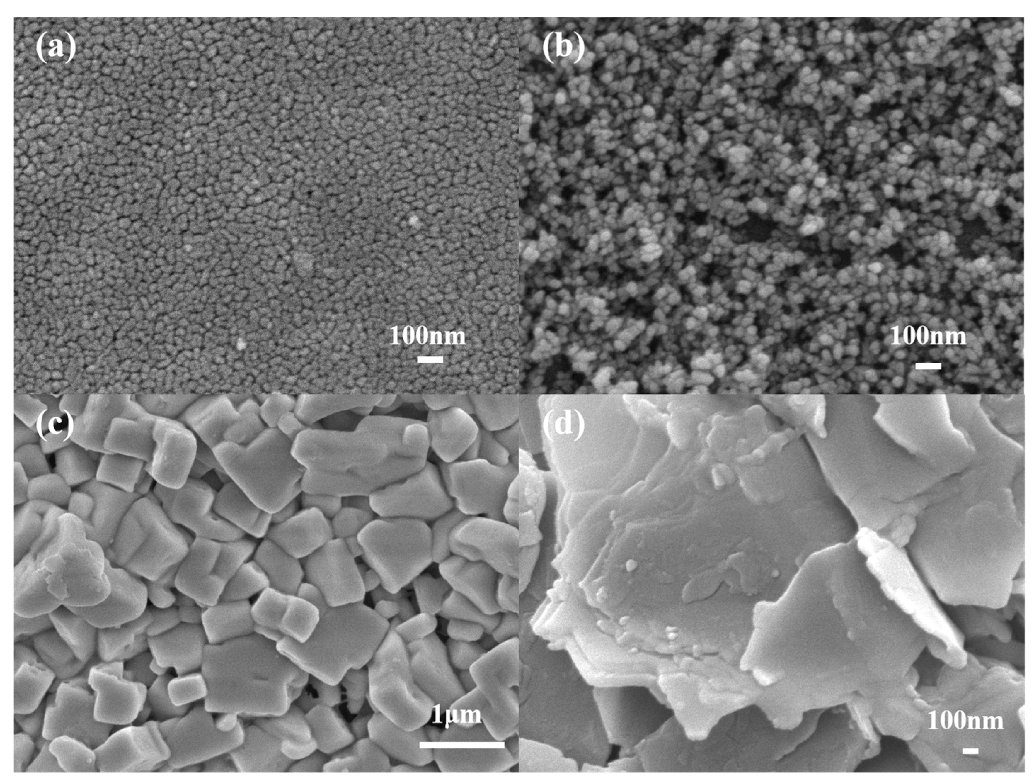
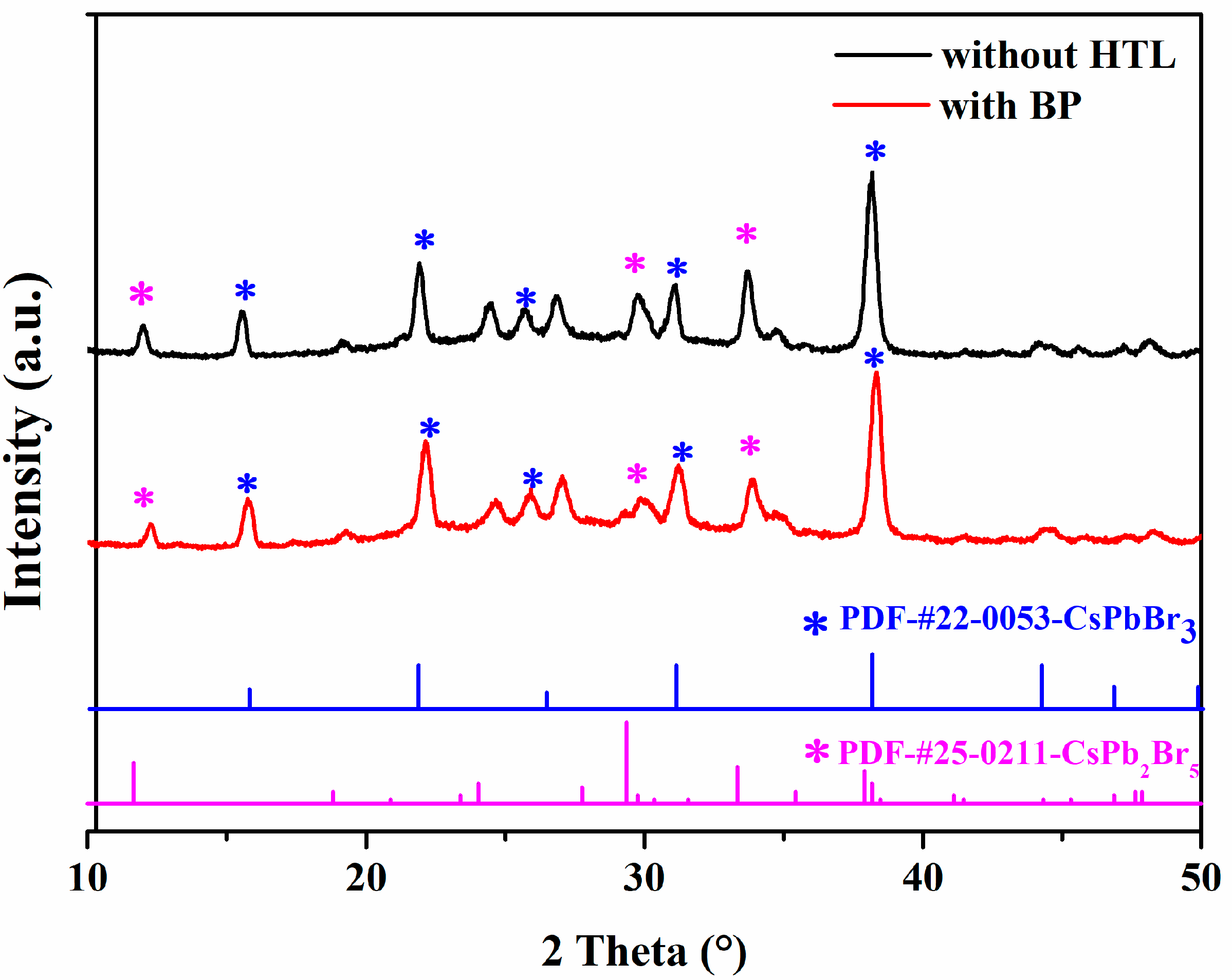
3.1. Characterization of SEM and XRD

Figure 2 shows the SEM images of the c-TiO2 layer, m-TiO2 layer, perovskite layer, and BP prepared under optimal conditions. From Figure 2a, we can see that the c-TiO2 layer consists of densely packed nanoparticles, forming a smooth and compact structure. This smooth, dense layer can effectively block holes, suppress charge recombination, reduce the leakage current, and prevent battery short circuits. From Figure 2b, it is seen that the m-TiO2 layer has many nanopores, which will serve as a good carrier for the injection of perovskite. From Figure 2c, it is seen that the CsPbBr3 film is smooth, dense, and has good crystallinity. Figure 2d shows the SEM image of BP on the perovskite surface. It is clearly observable that a layer of BP, which is a nanometer-scale two-dimensional layered structure, is coated on top of the perovskite. To investigate the effect of BP as a hole transport layer on the crystal structure of perovskite, we conducted XRD tests on CsPbBr3 films and BP. The results, shown in Figure 3, reveal four characteristic peaks centered at 15.8°, 21.9°, 25.6°, 31.1°, and 38.1°, which correspond to the main lattice planes (100), (110), (111), (200), and (210) of the CsPbBr3 phase, respectively. Additionally, three characteristic peaks of 12.0°, 29.7°, and 33.7° correspond to (002), (213), and (210) of the CsPb2Br5 phase. This is a common phenomenon in the two-step synthesis of CsPbBr3 films [31]. The characteristic peaks of the perovskite film are clear and sharp, indicating the successful formation of the CsPbBr3 crystal structure. The diffraction peak intensity of the perovskite film with BP about the CsPbBr3 phase is stronger, with sharper peaks at 25.6° and 31.1°. Among them, the three characteristic peaks of the CsPb2Br5 phase were decreased by 12.0°, 29.7°, and 33.7°. However, there is no peak shift, indicating that BP, as the HTL, did not enter the perovskite crystal, but instead reduced the interface defects of CsPbBr3 and improved its crystallinity.

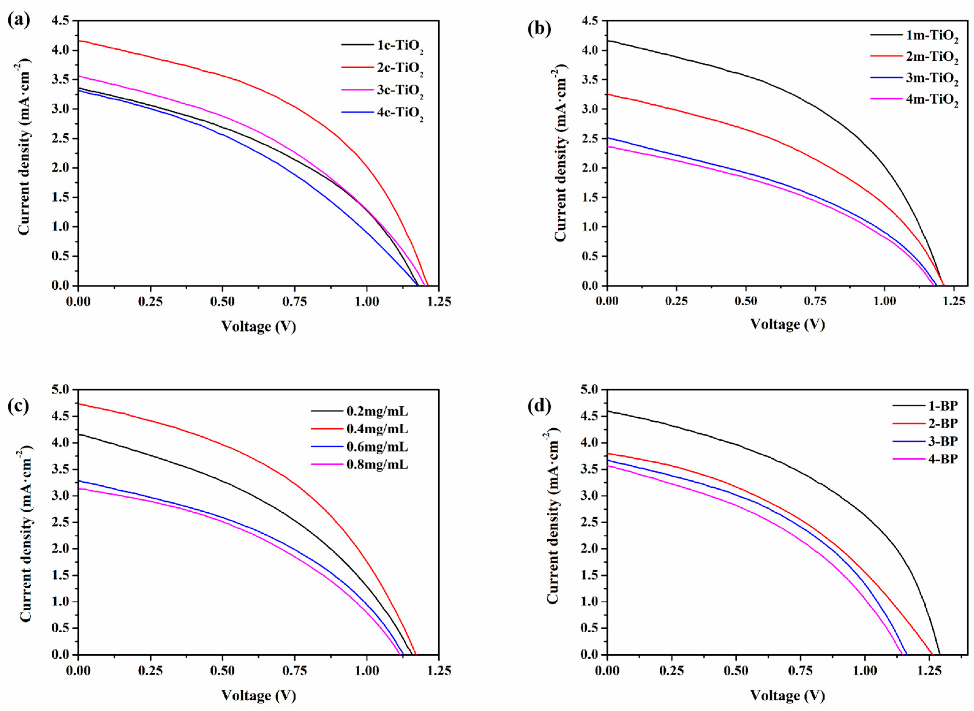
3.2. Preparation and Performance Regulation of CsPbBr3 Solar Cells Based on BP HTL

To investigate the optimal optoelectronic performance of CsPbBr3 PSCs, the preparation conditions of the batteries were optimized. Figure 3 shows the J-V curves of CsPbBr3 PSCs under different preparation conditions, while Table 1 lists the photovoltaic parameters of CsPbBr3 PSCs under the corresponding conditions: open-circuit voltage (Voc), short-circuit current (Jsc), fill factor (FF), and power conversion efficiency (PCE). First, we will explore the impact of the number of spin-coating cycles of c-TiO2 on the optoelectronic performance of the device. The spin-coating cycles of c-TiO2 are set to one, two, three, and four times, and J-V characteristic curve tests were conducted. As shown in Figure 4a and Table 1, when the spin-coating cycles of c-TiO2 are set to two, the battery achieves the best PCE of 2.31%. Next, using the optimized values for the spin-coating count of c-TiO2, the effect of m-TiO2 spin-coating the optoelectronic performance of the device was investigated, with the spin-coating counts for m-TiO2 being set to one, two, three, and four. From Figure 4b and Table 1, it can be observed that when the spin-coating count of m-TiO2 is one, the battery achieves the best optoelectronic efficiency. This may be because the permeability of the m-TiO2 layer decreases as the spin-coating count increases. Therefore, when the spin-coating count of m-TiO2 is one, it can improve the interface contact between the electron transport layer (ETL) and the perovskite layer, while having a minimal impact on the light absorption performance of the CsPbBr3 perovskite layer. Next, using the optimized values for ETL components, the effect of the BP concentrations was investigated, with the BP concentrations being set at 0.2, 0.4, 0.6, and 0.8 mg/mL. From Figure 4c and Table 1, it can be observed that when the BP concentration is 0.4 mg/mL, the device achieves the optimal photoelectric efficiency of 2.42%. Finally, using the optimized values for the ETL components and BP concentration, the effect of the BP spin-coating times on the device’s optoelectronic performance was studied, with the spin-coating times for BP being set at 0.2, 0.4, 0.6, and 0.8 mg/mL. According to Figure 4d and Table 1, it can be observed that when the spin-coating time for BP is one, the device achieves the best optoelectronic efficiency of 2.70%.

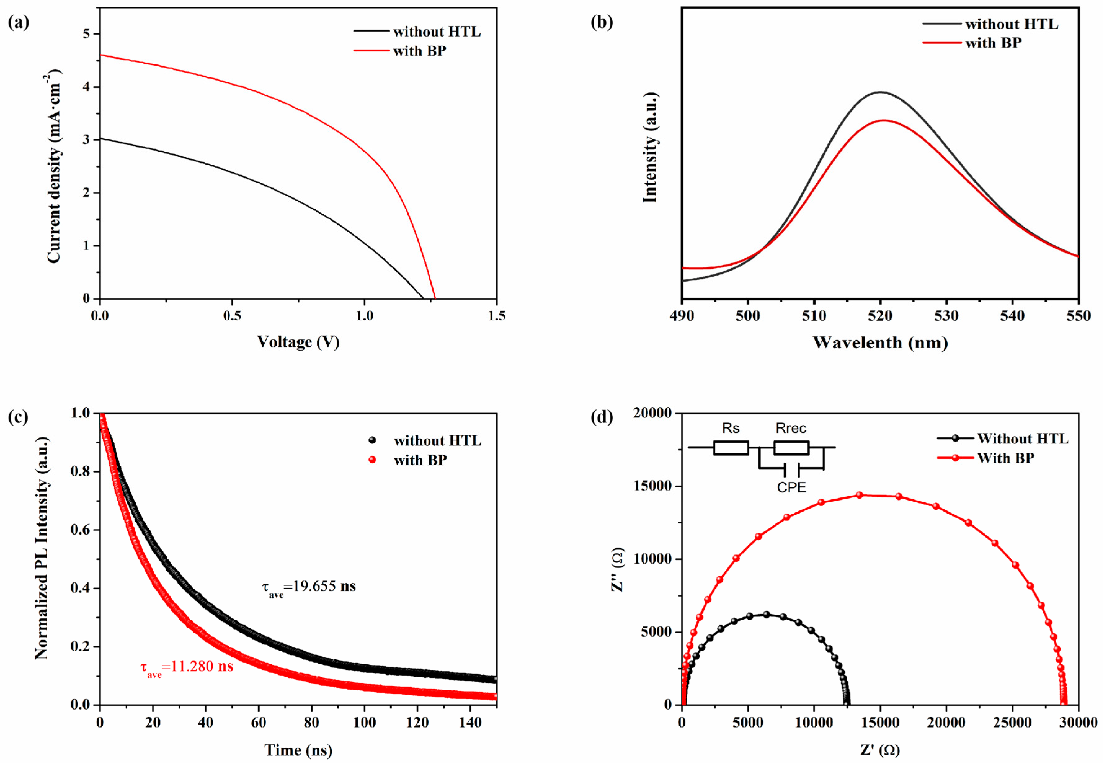
3.3. Photovoltaic Characteristics of CsPbBr3 Solar Cells Based on BP HTL

Figure 5a shows the J-V characteristics of CsPbBr3 PSCs using 0.4 mg/mL BP as the HTL and those without HTL, under illumination at an intensity of 100 mW/cm2. The photovoltaic parameters are listed in Table 2. The PCE of CsPbBr3 PSCs without HTL is 1.27%, with Voc at 1.22 V, Jsc at 2.65 mA/cm2, and FF at 39.51%. In contrast, PSCs using 0.4 mg/mL BP as the HTL exhibit a higher Voc of 1.29 V, Jsc of 4.60 mA/cm2, and FF of 45.52%, thereby increasing the PCE to 2.70%. To further investigate the principle of BP as a HTL in enhancing the optoelectronic performance of CsPbBr3 PSCs, PL spectroscopy and TRPL testing were conducted on perovskites with and without a HTL. Steady-state light can reflect the recombination and separation of electrons and holes in perovskite materials. When a HTL is present on the perovskite layer, the layer is excited by light, causing the separation of electrons and holes, with holes transferring to the HTL, leading to PL quenching. The more pronounced the PL quenching effect, the lower the intensity of the PL emission peak, indicating that the charge transfer at the interface occurs more rapidly [32]. From Figure 5b, it is seen that CsPbBr3 without a hole transport layer exhibits a strong fluorescence peak, indicating that the recombination of electrons and holes is quite severe in the absence of a hole transport layer. The PL intensity of the perovskite film with BP as the HTL is about 1.15 times lower than that of the perovskite film without a HTL. This suggests that the degree of recombination in the perovskite with BP as the HTL is smaller, and it also proves that BP has good hole extraction capabilities, effectively extracting holes from the light absorption layer and significantly reducing the recombination of electrons and holes. Figure 5c compares the TRPL spectra of perovskite films with and without BP as the HTL. Table 3 lists the TRPL spectral parameters for CsPbBr3 films without the HTL and CsPbBr3 films with BP as the HTL. The TRPL data were fitted using biexponential decay with a fast decay lifetime (τ1) and slow decay lifetime (τ2): I(t) = A1 exp(−t/τ1) + A2 exp(−t/τ2). Among them, τ1 mainly represents the non-radiative recombination caused by grain boundaries and surface trap states, while τ2 is attributed to the radiative recombination of free-charge carriers. The τ1 and τ2 for FTO/CsPbBr3 are 4.931 ns and 23.961 ns, respectively. In comparison, for FTO/CsPbBr3/BP, τ1 and τ2 decrease to 4.055 ns and 14.337 ns, respectively. This indicates that BP has a high charge extraction capability, which can enhance the hole extraction ability of the device, allowing carriers to transfer more effectively from the perovskite layer to the HTL. This reduces the defect density and suppresses the charge recombination at the perovskite/HTL interface, thereby improving the photovoltaic performance of PSCs. Consequently, the use of BP as the HTL significantly enhances the Jsc and FF of CsPbBr3 PSCs, consistent with the measurement results shown in Figure 5a. Figure 5d shows the electrochemical impedance spectra (EIS) of CsPbBr3 PSC devices with and without HTL, using 0.4 mg/mL BP as the HTL. Here, Rs represents the transfer resistance within the entire PSC, Rrec corresponds to the internal charge recombination resistance indicated by the semicircle, and CPE refers to the phase angle element. Table 4 lists the EIS parameters of CsPbBr3 PSCs with 0.4 mg/mL BP as the HTL and without HTL. In the devices of FTO/c-TiO2/m-TiO2/CsPbBr3/C and FTO/c-TiO2/m-TiO2/CsPbBr3/BP/C, Rrec is the dominant factor. The Rrec value of BP as the HTL in CsPbBr3 PSC devices is 28,862 Ω, which is significantly higher than that of CsPbBr3 PSC devices without an HTL (Rrec = 12,397 Ω). Meanwhile, the Rs of the without-HTL PSC was 91.37 Ω, which was significantly smaller than the Rs of with-BP PSCs. This indicates that BP notably inhibits the non-radiative recombination, improves the charge transmission efficiency, and passivates the device defects. This may be due to the interaction between P in BP and Pb in perovskite, which leads to a reduction in defects and an increase in the Rrec value. This effectively suppresses charge recombination, facilitating the extraction of charge carriers in the device, thereby enhancing the FF and Jsc. Figure 6a,b is the UV spectra and Tauc plot of the perovskite thin film without a hole transport layer. The data indicate that the bandgap of CsPbBr3 is 2.34 eV, which is consistent with the values reported in the literature for CsPbBr3 [32]. With the above-calculated energy bands and the data from the reference [23], the energy band diagram of the CsPbBr3 PSC can be drawn, which is shown in Figure 6c. Here, we can see that the maximum valence band (EVB) of the CsPbBr3 layer film is −5.62 V, while the maximum valence band of BP is −5.2 V. As a hole transport layer (HTL), BP reduces the energy offset for hole extraction, which facilitates a faster hole transfer and suppresses hole accumulation at the interface, thereby improving the device’s photoelectric conversion efficiency.

3.4. Stability Testing

The stability of CsPbBr3 PSCs is a key factor for their commercialization. Figure 7 compares the PCE stability tests of PSCs with and without BP HTL. After being stored in air at a relative humidity (RH) of 25–65% and a temperature of 25 °C for 500 h, the unencapsulated optimal PSCs retained 69% of their initial PCE. In contrast, the PSCs without the HTL showed significant degradation, losing 48% of their initial PCE. This indicates that BP is in close contact with the perovskite layer and the carbon layer. Due to the protection provided by the carbon layer, the degradation rate of BP is slower, which enhances the air stability of the PSCs. Additionally, incorporating BP into the perovskite layer can passivate the Pb0 defects in the perovskite layer, thereby improving the stability of the device, which is consistent with previous theoretical studies [21].

4. Conclusions

In summary, BP can effectively adjust the interface contact of CsPbBr3/Carbon, reduce charge recombination, and facilitate the extraction of interface charge carriers. At the same time, BP, as a hole transport layer, enhances the hole extraction capability of CsPbBr3 PSCs, leading to improved Jsc and FF. Ultimately, this significantly enhances the optoelectronic performance of all-inorganic CsPbBr3 PSCs, achieving an optimal PCE of 2.70%, with a Voc of 1.29 V, Jsc of 4.60 mA/cm2, and FF of 48.58%. In addition, after being stored for 500 h in air with an RH of 25–65% and a temperature of 25 °C, the unencapsulated optimal PSCs still retained 69% of their initial PCE. This demonstrates that BP, used as a hole transport layer, can effectively enhance the stability of PSCs, indicating a promising application potential for BP materials in practical use. However, the instability of BP in the air and its susceptibility to oxidation limit its application in solar cells. Improving the air stability of BP remains a key issue for its widespread use. Additionally, the poor phase stability and higher bandgap of the CsPbBr3 crystal structure result in significantly lower cell efficiency compared to organic–inorganic hybrid PSCs. How to optimize the interaction between BP and CsPbBr3, reduce the density of defect states, and enhance the stability of CsPbBr3 PSCs continue to pose a major challenge for BP-based all-inorganic perovskite solar cells.

Author Contributions

Conceptualization, S.X. and L.Y.; methodology, S.X.; software, S.X. and F.L.; validation, S.X., L.Y. and Z.W.; formal analysis, J.Z., Y.D. and D.L.; investigation, S.X., L.Y. and Z.W.; resources, L.Y. and F.L.; data curation, S.X. and F.L.; writing—review and editing, X.Z. and W.S.; visualization, W.S.; supervision, X.Z.; project administration, X.Z.; funding acquisition, X.Z. All authors have read and agreed to the published version of the manuscript.

Funding

This research was funded by the Hainan Provincial Natural Science Foundation of High Level-talent Project (220RC594), the National Natural Science Foundation of China (22102043), and the Open Foundation of Engineering Research Center of Environment-Friendly Functional Materials, Ministry of Education (EFFM-202101).

Institutional Review Board Statement

Not applicable.

Informed Consent Statement

Not applicable.

Data Availability Statement

The original contributions presented in the study are included in the article, further inquiries can be directed to the corresponding author.

Conflicts of Interest

The authors declare no conflicts of interest.

References

  1. Kojima, A.; Teshima, K.; Shirai, Y.; Miyasaka, T. Organometal Halide Perovskites as Visible-Light Sensitizers for Photovoltaic Cells. J. Am. Chem. Soc. 2009, 131, 6050–6051. [Google Scholar] [CrossRef] [PubMed]
  2. Kim, H.-S.; Lee, C.-R.; Im, J.-H.; Lee, K.-B.; Moehl, T.; Marchioro, A.; Moon, S.-J.; Humphry-Baker, R.; Yum, J.-H.; Moser, J.E.; et al. Lead Iodide Perovskite Sensitized All-Solid-State Submicron Thin Film Mesoscopic Solar Cell with Efficiency Exceeding 9%. Sci. Rep. 2012, 2, 591. [Google Scholar] [CrossRef] [PubMed]
  3. Han, Q.; Bae, S.H.; Sun, P.; Hsieh, Y.T.; Yang, Y.M.; Rim, Y.S.; Zhao, H.; Chen, Q.; Shi, W.; Li, G.; et al. Single Crystal Formamidinium Lead Iodide (FAPbI3): Insight into the Structural, Optical, and Electrical Properties. Adv. Mater. 2016, 28, 2253–2258. [Google Scholar] [CrossRef]
  4. Zhang, P. All Inorganic Perovskite Solar Cells and Absorption Layer Band Gap Regulation. Master’s Thesis, Henan University, Zhengzhou, China, 2019. [Google Scholar]
  5. National Renewable Energy Laboratory. Best Research-Cell Efficiency Chart; National Renewable Energy Laboratory: Golden, CO, USA, 2024. Available online: https://www.nrel.gov/pv/cell-efficiency.html (accessed on 22 July 2024).
  6. Bryant, D.; Aristidou, N.; Pont, S.; Sanchez-Molina, I.; Chotchunangatchaval, T.; Wheeler, S.; Durrant, J.R.; Haque, S.A. Light and oxygen induced degradation limits the operational stability of methylammonium lead triiodide perovskite solar cells. Energy Environ. Sci. 2016, 9, 1655–1660. [Google Scholar] [CrossRef]
  7. Chen, Y.-C.; Lin, W.-J.; Chiu, C.-C.; Juwita, R.; Tsai, H.-H.G. First-Principles Investigation of the Thermal Degradation Mechanisms of Methylammonium Lead Triiodide Perovskite. J. Phys. Chem. C 2020, 124, 14521–14530. [Google Scholar] [CrossRef]
  8. Imran, M.; Saleem, A.; Khan, N.A.; Kamboh, A.H. Enhanced efficiency and stability of perovskite solar cells by partial replacement of CH3NH3+ with inorganic Cs+ in CH3NH3PbI3 perovskite absorber layer. Phys. B Condens. Matter 2019, 572, 1–11. [Google Scholar] [CrossRef]
  9. Kulbak, M.; Gupta, S.; Kedem, N.; Levine, I.; Bendikov, T.; Hodes, G.; Cahen, D. Cesium Enhances Long-Term Stability of Lead Bromide Perovskite-Based Solar Cells. J. Phys. Chem. Lett. 2015, 7, 167–172. [Google Scholar] [CrossRef] [PubMed]
  10. Duan, J.; Zhao, Y.; He, B.; Tang, Q. High-Purity Inorganic Perovskite Films for Solar Cells with 9.72 % Efficiency. Angew. Chem. Int. Ed. Engl. 2018, 57, 3787–3791. [Google Scholar] [CrossRef] [PubMed]
  11. Sutton, R.J.; Eperon, G.E.; Miranda, L.; Parrott, E.S.; Kamino, B.A.; Patel, J.B.; Hörantner, M.T.; Johnston, M.B.; Haghighirad, A.A.; Moore, D.T.; et al. Bandgap-Tunable Cesium Lead Halide Perovskites with High Thermal Stability for Efficient Solar Cells. Adv. Energy Mater. 2016, 6, 1502458. [Google Scholar] [CrossRef]
  12. Abhishek, S.; Marshall, A.R.; Sanehira, E.M.; Chernomordik, B.D.; Moore, D.T.; Christians, J.A.; Chakrabarti, T.; Luther, J.M. Quantum dot–induced phase stabilization of α-CsPbI3 perovskite for high-efficiency photovoltaics. Science 2016, 354, 92–95. [Google Scholar] [CrossRef]
  13. Wang, Y.; Zhang, T.; Xu, F.; Li, Y.; Zhao, Y. A Facile Low Temperature Fabrication of High Performance CsPbI2Br All-Inorganic Perovskite Solar Cells. Sol. RRL 2018, 2, 1700180. [Google Scholar] [CrossRef]
  14. Chen, W.; Chen, H.; Xu, G.; Xue, R.; Wang, S.; Li, Y.; Li, Y. Precise Control of Crystal Growth for Highly Efficient CsPbI2Br Perovskite Solar Cells. Joule 2019, 3, 191–204. [Google Scholar] [CrossRef]
  15. Ma, Q.; Huang, S.; Wen, X.; Green, M.A.; Ho-Baillie, A.W.Y. Hole Transport Layer Free Inorganic CsPbIBr2 Perovskite Solar Cell by Dual Source Thermal Evaporation. Adv. Energy Mater. 2016, 6, 1502202. [Google Scholar] [CrossRef]
  16. Steele, J.A.; Jin, H.; Dovgaliuk, I.; Berger, R.F.; Braeckevelt, T.; Yuan, H.; Martin, C.; Solano, E.; Lejaeghere, K.; Rogge, S.M.J.; et al. Thermal unequilibrium of strained black CsPbI3 thin films. Science 2019, 365, 679–684. [Google Scholar] [CrossRef]
  17. Yuan, S.; Deng, J.; Xiong, H.; Wu, W.; Ma, Z.; Wang, M.; Li, W.; Fan, J. In-depth understanding the temperature-dependent reversible phase transition in CsPbI3-XBrX perovskites and its associated photophysical properties. J. Mater. Chem. A 2023, 11, 19685–19695. [Google Scholar] [CrossRef]
  18. Hou, S.; Wu, S.; Li, X.; Yan, J.; Xing, J.; Liu, H.; Hao, H.; Dong, J.; Huang, H. Efficient CsPbBr3 Perovskite Solar Cells with Storage Stability > 340 Days. Energies 2022, 15, 7740. [Google Scholar] [CrossRef]
  19. Zou, L.; Li, X.; Yang, M.; Yan, J.; Wang, J.; Cheng, J.; Xing, J.; Liu, H.; Hao, H.; Dong, J. ZnPc/CsPbBr3 QDs collaborative interface modification to improve the performance of CsPbBr3 perovskite solar cells. Sol. Energy Mater. Sol. Cells 2023, 251, 112157. [Google Scholar] [CrossRef]
  20. Zhang, M.; Biesold, G.M.; Lin, Z. A multifunctional 2D black phosphorene-based platform for improved photovoltaics. Chem. Soc. Rev. 2021, 50, 13346–13371. [Google Scholar] [CrossRef] [PubMed]
  21. Yin, T.; Long, L.; Tang, X.; Qiu, M.; Liang, W.; Cao, R.; Zhang, Q.; Wang, D.; Zhang, H. Advancing Applications of Black Phosphorus and BP-Analog Materials in Photo/Electrocatalysis through Structure Engineering and Surface Modulation. Adv. Sci. 2020, 7, 2001431. [Google Scholar] [CrossRef] [PubMed]
  22. Gong, X.; Guan, L.; Li, Q.; Li, Y.; Zhang, T.; Pan, H.; Sun, Q.; Shen, Y.; Grätzel, C.; Zakeeruddin, S.M.; et al. Black phosphorus quantum dots in inorganic perovskite thin films for efficient photovoltaic application. Sci. Adv. 2020, 6, eaay5661. [Google Scholar] [CrossRef] [PubMed]
  23. Aidarkhanov, D.; Yelzhanova, Z.; Ren, Z.; Nigmetova, G.; Lau, S.P.; Balanay, M.P.; Hu, H.; Surya, C.; Djurišić, A.B.; Ng, A. Synergic effects of incorporating black phosphorus for interfacial engineering in perovskite solar cells. Surf. Interfaces 2023, 43, 103531. [Google Scholar] [CrossRef]
  24. Zhang, M.; Ye, M.; Wang, W.; Ma, C.; Wang, S.; Liu, Q.; Lian, T.; Huang, J.; Lin, Z. Synergistic Cascade Carrier Extraction via Dual Interfacial Positioning of Ambipolar Black Phosphorene for High-Efficiency Perovskite Solar Cells. Adv. Mater. 2020, 32, 2000999. [Google Scholar] [CrossRef]
  25. Lin, S.; Liu, S.; Yang, Z.; Li, Y.; Ng, T.W.; Xu, Z.; Bao, Q.; Hao, J.; Lee, C.-S.; Surya, C.; et al. Solution-Processable Ultrathin Black Phosphorus as an Effective Electron Transport Layer in Organic Photovoltaics. Adv. Funct. Mater. 2016, 26, 864–871. [Google Scholar] [CrossRef]
  26. Gu, B.; Du, Y.; Chen, B.; Zhao, R.; Lu, H.; Xu, Q.; Guo, C. Black Phosphorus Quantum Dot-Engineered Tin Oxide Electron Transport Layer for Highly Stable Perovskite Solar Cells with Negligible Hysteresis. ACS Appl. Mater. Interfaces 2022, 14, 11264–11272. [Google Scholar] [CrossRef] [PubMed]
  27. Muduli, S.K.; Varrla, E.; Kulkarni, S.A.; Han, G.; Thirumal, K.; Lev, O.; Mhaisalkar, S.; Mathews, N. 2D black phosphorous nanosheets as a hole transporting material in perovskite solar cells. J. Power Sources 2017, 371, 156–161. [Google Scholar] [CrossRef]
  28. Dong, W.; Xiong, S.; Yang, J.; Qiao, W.; Zeng, Q.; Wang, X.; Yao, Y.; Bao, Q. Black phosphorus doped Poly(triarylamine) as hole transport layer for highly efficient perovskite solar cells. Org. Electron. 2021, 89, 106052. [Google Scholar] [CrossRef]
  29. Liu, S.; Lyu, J.; Zhou, D.; Zhuang, X.; Shi, Z.; Sun, R.; Liu, L.; Wu, Y.; Liu, B.; Liu, D.; et al. Dual Modification Engineering via Lanthanide-Based Halide Quantum Dots and Black Phosphorus Enabled Efficient Perovskite Solar Cells with High Open-Voltage of 1.235 V. Adv. Funct. Mater. 2022, 32, 2112647. [Google Scholar] [CrossRef]
  30. Huang, H.; Li, J.; Yi, Y.; Wang, J.; Kang, Y.; Chu, P.K.; Ong, H.C.; Yu, X.F. In situ growth of all-inorganic perovskite nanocrystals on black phosphorus nanosheets. Chem. Commun. 2018, 54, 2365–2368. [Google Scholar] [CrossRef] [PubMed]
  31. Cheng, J.; Yan, J.; Wang, J.; Jiang, Y.; Xing, J.; Liu, H.; Hao, H.; Dong, J. Preparation of CsPbBr3 Perovskite Solar Cells Using a Green Solvent. Energies 2023, 16, 6426. [Google Scholar] [CrossRef]
  32. Song, Q.; Zhang, H.; Jin, X.; Wang, H.; Wang, P.; Ijaz, M.; Xu, Q. Highly Stable All-inorganic CsPbBr3 Perovskite Solar Cells Based on Pulsed Laser Deposition. Appl. Phys. Lett. 2023, 123, 092103. [Google Scholar] [CrossRef]
Figure 1. Preparation process of the FTO/c-TiO2/m-TiO2/CsPbBr3/BP/C device.
Materials 18 00415 g001
Figure 2. SEM images: (a) c-TiO2 layer, (b) m-TiO2 layer, (c) CsPbBr3 layer, and (d) BP on the surface of CsPbBr3.
Materials 18 00415 g002
Figure 3. XRD patterns of CsPbBr3 films without BP HTL and CsPbBr3 films with BP.
Materials 18 00415 g003
Figure 4. (a) J-V curves of CsPbBr3 PSC with different numbers of c-TiO2 spin-coating; (b) J-V curves of CsPbBr3 PSC with different numbers of m-TiO2 spin-coating; (c) J-V curves of CsPbBr3 PSC with different BP concentrations; (d) J-V curves of CsPbBr3 PSC with different numbers of BP spin-coating.
Materials 18 00415 g004
Figure 5. (a) J-V curves of CsPbBr3 PSCs with and without HTL under a light intensity of 100 mW/cm2; (b) PL of CsPbBr3 films without HTL and CsPbBr3/BP films; (c) TRPL of CsPbBr3 films without HTL and CsPbBr3/BP films; (d) Impedance plots of CsPbBr3 PSCs with and without HTL, using 0.4 mg/mL BP as HTL.
Materials 18 00415 g005
Figure 6. (a) UV–vis spectra of the CsPbBr3 film without HTL, (b) Tauc plot, (c) Band alignment of perovskite solar cells with BP.
Materials 18 00415 g006
Figure 7. Under ambient air conditions at room temperature and relative humidity ranging from 25% to 65%. Comparison of the stability of unencapsulated CsPbBr3 PSC with BP as HTL and without HTL.
Materials 18 00415 g007
Table 1. Photovoltaic parameters (Voc, Jsc, FF, and PCE) of CsPbBr3 PSC with different c-TiO2 spin-coating times, different m-TiO2 spin-coating times, different BP concentrations, and different BP spin-coating times.
SampleVoc (V)Jsc (mA/cm2)FF (%)PCE (%)
1c-TiO21.183.3640.551.61
2c-TiO21.214.1545.982.31
3c-TiO21.203.5639.731.70
4c-TiO21.183.3136.681.43
1m-TiO21.214.1545.982.31
2m-TiO21.213.2540.961.61
3m-TiO21.192.4738.021.12
4m-TiO21.212.2239.861.07
0.2 mg/mL BP1.164.1539.451.90
0.4 mg/mL BP1.174.7343.702.42
0.6 mg/mL BP1.133.2840.251.49
0.8 mg/mL BP1.123.1340.021.40
1-BP1.294.6045.522.70
2-BP1.263.8040.021.91
3-BP1.163.6742.561.81
4-BP1.153.5739.711.63
Table 2. Photovoltaic parameters (including Voc, Jsc, FF, and PCE) of CsPbBr3 PSCs with 0.4 mg/mL BP as the HTL and without HTL, under a light intensity of 100 mW/cm2.
SampleVoc (V)Jsc (mA/cm2)FF (%)PCE (%)
Without HTL1.222.6539.511.27
With BP1.153.5739.711.63
Table 3. TRPL spectral parameters of CsPbBr3 thin films without HTL and CsPbBr3/BP thin films.
Structureτ1τ2
Without HTL4.93123.961
with BP4.05514.337
Table 4. EIS parameters of CsPbBr3 PSC with 0.4 mg/mL BP as HTL and without HTL.
SampleRs (Ω)Rrec (Ω)CPE
Without HTL91.3712,3979.554 × 10−9
With BP22.7528,8626.798 × 10−9
Disclaimer/Publisher’s Note: The statements, opinions and data contained in all publications are solely those of the individual author(s) and contributor(s) and not of MDPI and/or the editor(s). MDPI and/or the editor(s) disclaim responsibility for any injury to people or property resulting from any ideas, methods, instructions or products referred to in the content.

