Article

Microstructure, Hardness, and Wear Behavior of Layers Obtained by Electric Arc Hardfacing Processes

by
Sebastian Balos
1,
Danka Labus Zlatanović
2,
Petar Janjatović
1,
Milan Pećanac
1,
Olivera Erić Cekić
3,4,
Milena Rosić
5,* and
Srećko Stopić
6,*
1
Department of Production Engineering, Faculty of Technical Sciences, University of Novi Sad, Trg Dositeja Obradovica 6, 21000 Novi Sad, Serbia
2
Department of Production Technology, Technische Universität Ilmenau, 98693 Ilmenau, Germany
3
Innovation Center, Faculty of Mechanical Engineering, University of Belgrade, Kraljice Marije 16, 11120 Belgrade, Serbia
4
Faculty of Mechanical and Civil Engineering in Kraljevo, University of Kragujevac, Dositejeva 19, 36000 Kraljevo, Serbia
5
“Vinča” Institute of Nuclear Sciences, National Institute of the Republic of Serbia, University of Belgrade, Mike Petrovića Alasa 12-14, 11351 Belgrade, Serbia
6
IME Process Metallurgy and Metal Recycling, RWTH Aachen University, Intzestraße 3, 52056 Aachen, Germany
*
Authors to whom correspondence should be addressed.
Materials 2025, 18(2), 299; https://doi.org/10.3390/ma18020299
Submission received: 4 December 2024 / Revised: 6 January 2025 / Accepted: 8 January 2025 / Published: 10 January 2025

Abstract

:
Hardfacing is a welding-related technique aimed at depositing a harder and tougher layer onto a softer, less wear-resistant substrate or base metal. This process enhances the abrasion resistance of the component, increasing its durability under working conditions. A key feature of hardfacing is dilution, which refers to the mixing of the hardfacing layer and the base metal. In this study, shielded metal arc welding (SMAW) was employed to hardface structural steel using chromium carbide vanadium consumables, with results compared to AISI D2 cold-work tool steel. Four different SMAW parameters were tested, and the abrasive test was conducted against SiC discs. Wear rate, represented by the wear loss rate, was correlated to microstructure, scanning electron microscopy, energy-dispersive X-ray spectroscopy, hardness, microhardness, and surface roughness. The results showed that key SMAW parameters, such as welding speed and current, significantly influence wear resistance. Specifically, slower welding speeds and higher currents, which result in greater heat input, led to the increased wear resistance of the deposited layer through the mechanism of the inoculation of larger and harder carbides.

1. Introduction

Hardfacing is a deposition technique that can be applied to various base materials, most commonly relatively affordable structural materials, such as steel. The aim of hardfacing is twofold: to restore dimensions, i.e., re-establish the shape and size of the worn or corroded part, or to impart entirely new properties to a newly produced component [1,2].
This technological process can significantly enhance resistance to wear caused by abrasion, impact, adhesion, corrosion, heat, or a combined effect of any of the mentioned properties [3,4]. Thus, hardfacing can improve the service life of fabricated parts and prevent fractures and breakdowns in a cost-effective manner for both maintenance and manufacturing. Maintenance costs are reduced, since hardfaced parts have a longer life and are less prone to failure. Therefore, instead of replacing these failed parts, they can be repaired or regularly maintained through on-site hardfacing, thereby reducing both planned and unplanned downtime. Furthermore, production costs can be lower, since only the surface layer is made of expensive material, while base materials are typically made of low-cost materials that are easy to fabricate and join by welding if needed [5,6,7]. Hardfacing is generally a cost-effective technology and can be performed using existing welding equipment.
The most common welding techniques used for hardfacing include arc welding, gas-shielded arc welding, and powder-based welding. Among arc welding processes, the most common are shielded metal arc welding (SMAW) [8,9] and submerged arc welding [10,11]. Gas-shielded metal arc processes include gas tungsten arc welding (GTAW) [5,6], gas metal arc welding (GMAW), as well as flux cored arc welding (FCAW), and metal cored arc welding (MCAW) [12,13,14]. Finally, for powder-based processes, plasma transfer arc welding (PTAW) [15,16,17] and laser cladding/welding (LC/LW) are the most common, with the latter becoming increasingly attractive due to a drop in cost [15,18].
A wide range of hardfacing techniques corresponds to the diverse welding processes that encompass the majority of industrial joining technologies. Furthermore, this diversity is reflected in the variety of materials that can be deposited, which in turn, influences applications in various industries, such as agriculture, mining, nuclear, construction, general manufacturing, and railways. Even the defense industry has benefited from hardfacing, as several studies have explored its potential to enhance ballistic protection against kinetic energy projectiles [19,20].
Hardfacing consumables can generally be categorized into four main groups, closely corresponding to their base alloy: cobalt-based, nickel-based, tungsten-based, and iron-based [9,21]. Cobalt-based alloys also contain Cr, W, Ni, Mo, and C, providing good wear resistance combined with corrosion and heat resistance, offering excellent versatility, but at a relatively high cost. Furthermore, Co is considered a critical raw material in the European Union and is often targeted to be fully or partially replaced by Ni. Compared to Ni-based alloys, Co-based hardfacing alloys offer better weldability [22,23,24]. Ni-based alloy deposits (Ni-) combine abrasion resistance (due to additions of C, B, and Nb) with corrosion resistance (from Cr and Al additions), particularly at high temperatures (with W and Mo) [25,26]. Tungsten alloys, often referred to as cemented carbides, consist of tungsten carbide (WC) particles with a binder, mainly Co. These deposits have extreme abrasion resistance due to their very high hardness. However, unlike other high-hardness materials, such as sintered ceramics, these alloys have a Co binder that offsets the brittleness of WC and provides resistance to impact loading [25,27]. On the other hand, there is ongoing interest in partially replacing WC and Co as critical raw materials in the EU [24].
Iron-based alloys are the most cost-effective and widely used hardfacing material. These alloys primarily contain C, Cr, Mo, and other elements, similar to those found in ferrous alloys. Fe-Cr-C hardfacing alloys are predominantly used for parts subject to grinding abrasion combined with light impact, such as digging teeth, conveyor screws, mixer wings, scraper blades, rendering plant equipment, and sand pumps (around 3% C and 30% Cr) [UTP Voestapline WEARstick XD60 brochure, accessed on 19 December 2024; UTP Voestapline WEARstick XD61 brochure, accessed on 19 December 2024]. Alloys containing around 4.5% C and 20–25% Cr are suitable for extreme sliding abrasion, including at temperatures up to 500 °C, due to their extremely high abrasion resistance from the very high content of special carbides based on Mo, V, W, and Nb. Their main applications are in earth-moving equipment, the cement and brick industry, and steel mills for radial breakers and revolving bar screens in sintering plants [UTP Voestapline WEARstick XD65 brochure, accessed on 19 December 2024]. Alloys with around 6.5% C and 25% Cr are suitable for hardfacing parts subjected to heavy abrasion with moderate impact. Typical applications include parts for cement presses, brick presses, refractory press screws, conveyor screws, and mixer blades, with service temperatures up to 450 °C [UTP Voestapline WEARstick XD63 brochure, accessed on 19 December 2024]. Their properties are closely related to their microstructure, where Cr-C or Cr-C-B carbides are mixed with the matrix containing one or more common microstructures in ferrous alloys, such as austenite, ferrite, and martensite [1,25,26]. Besides basic alloying elements, a small amount of Nb can be added. Correa et al. [11] reported positive results regarding the formation of primary NbC carbides randomly distributed in the matrix. These findings, despite the marginally lower hardness of the bulk material, resulted in the increased wear resistance of the SAW deposit. This confirmed an earlier study by Berns and Fischer [1,26]. Singh and Pandey [2] investigated the influence of several passes and SAW current, finding that an increased number of passes and a lower deposition current improved wear resistance. This was attributed to a higher hardness achieved in the third pass compared to the first. Additionally, a lower current resulted in higher cooling rates, leading to a transformation from a pearlitic to a martensitic matrix surrounding the carbides.
The primary aim of this research was to vary the microstructure and evaluate and compare the intensive abrasion resistance of four Fe-Cr-C deposits produced using manual SMAW processes with varying parameters. The performances of these deposits were benchmarked against AISI D2 cold-work tool steel in the heat-treated condition. The obtained wear rate results (weight loss rates) were correlated to the hardness and microhardness of the deposits, microstructures, particularly carbides, and the local chemical composition.

2. Materials and Methods

Hardfacing was performed on S235JR structural steel, with dimensions of 100 mm in length, 50 mm in width, and 30 mm in thickness. The 100 × 50 mm area was hardfaced. The chemical composition of the base metal is shown in Table 1. The consumable used was a rutile-coated electrode (Shielded Metal Arc Welding—SMAW process) from the WEARstick XD 60/UTP Ledurit 60 series (Voestalpine, Linz, Austria), belonging to the Fe-Cr-C type (E Fe14), with the nominal composition presented in Table 2. Hardfacing parameters for Specimens 1 to 4 are shown in Table 3, along with the deposit thickness range. The arc length was manually maintained at approximately 3 mm, with no preheating. Prior to the hardfacing process, the electrodes were dried at 300 °C for 2 h. The SMAW process was conducted on an Iskra E10 device (Iskra, Ljubljana, Slovenia). The hardfacing direction was longitudinal, with a push/forward orientation of the electrode, and the width was covered using stringer beads.
The reference material, which served the base material for the deposited material, was a rolled homogeneous plate made of a cold-work tool steel of the AISI D2 type in a heat-treated, hardened condition. This was selected as an alternative to FeCrC hardfacing on structural steel for application in rendering mills. In this application, a combination of wear and impact is expected, which is why the cold-work FeCrC alloy was chosen as the hardfacing material. This specimen was designated as Specimen D2. The chemical composition is presented in Table 4. Heat treatment involved austenitization at 980 °C, quenching in oil, and tempering at 450 °C to achieve a uniform hardness of 58 HRC. Hardness was measured using an HP-250 Rockwell hardness testing device (WPM-Werkstoffpruefmachinen, Leipzig, Germany).
The wear test was conducted on a customized metallographic laboratory polishing machine, the DP-U2 (Struers, Bellerup, Denmark). The customization involved replacing the polishing wheel with SiC grinding paper, which had a grit size of P100. According to the FEPA (Federation of European Producers of Abrasives), the corresponding SiC abrasive paper particle size is 162 µm, with a loading of 1500 g. Basic surface roughness parameters of the counterbody, based on five measurements, were as follows: Ra (arithmetic mean roughness value) of 3.261 ± 0.237 µm and Rz (maximum height of the profile) of 35.825 ± 3.415 µm. The specimens were mounted in a brass holder and placed in a Struers PdM-Force (Struers, Bellerup, Denmark) specimen mover–rotator. Prior to each wear test, each of the five tested specimens was ground using a full set of SiC abrasive papers: P100, P150, P240, P360, P500, P600, P800, P1000, P1500, and P2000.
The abrasive paper base in the wear testing spindle was set to a speed of 250 rpm, with a wear time of 60 s. The specimen axis was 70 mm away from the centerline of the spindle, giving a sliding distance of 109.9 m. The wear test was performed in a water environment at 15 °C, with a constant flow rate maintained at 100 mL/min. Specimen mass was measured using a Type 2615 analytic balance (Tehtnica, Zelezniki, Slovenia) with an accuracy of 0.1 mg, before and after the wear test. The results were calculated as the average weight loss rate of the five specimens. After wear testing, surface roughness was measured using the SJ-301 (Mitutoyo, Kawasaki, Japan) device, with the average for all five tested specimens reported. The measurement parameters were set to λc = 0.8 × 5 mm and λs = 2.5 mm, and the Gaussian filter method was applied with a tip radius of 2 µm and a tip angle of 60°. Two roughness parameters were measured, Ra and Rz.
The metallographic examination was conducted using a light microscope (LM) Orthoplan (Leitz, Wetzlar, Germany), equipped with an ocular micrometer to measure the heat-affected zone (HAZ) width. Additionally, metallographic examination and chemical composition analysis of phases were carried out using a JSM-6460LV scanning electron microscope (SEM) equipped with an Inca Microanalysis system (Oxford Instruments, Abingdon, UK) for energy-dispersive X-ray spectroscopy (EDS), to evaluate the chemical composition of different phases. Prior to SEM analysis, the specimens were coated with gold using the Leica SCD-005 apparatus (Ball-Tech, Leica—Leitz, Wetzlar, Germany). Metallographic preparation before microscopic examination included grinding with SiC abrasive papers (P150, P240, P360, P500, P600, P800, P1000, P1500, and P2000), polishing with 6, 1, and ¼ μm diamond suspensions, and etching the hardfaced layer with Aqua Regia (17% HNO3, 50% HCl in glycerol). Base metal in the hardfaced specimens and the reference cold-work D2 tool steel were etched with Nital (3% HNO3 in ethanol). SEM was also used to examine the surface topography of worn surfaces.
To evaluate the hardness of the specimens, the Vickers method was applied. The HPO-250 (WPM, Leipzig, Germany). Vickers hardness measurement device was used. The microhardness of specific phases was tested using the Wilson Tukon-1101 (Buehler, Uzwil, Switzerland), with a minimal load of 10 g. Both methods used a dwell time of 15 s. For each hardness test, five measurements were taken, and the average value was reported.

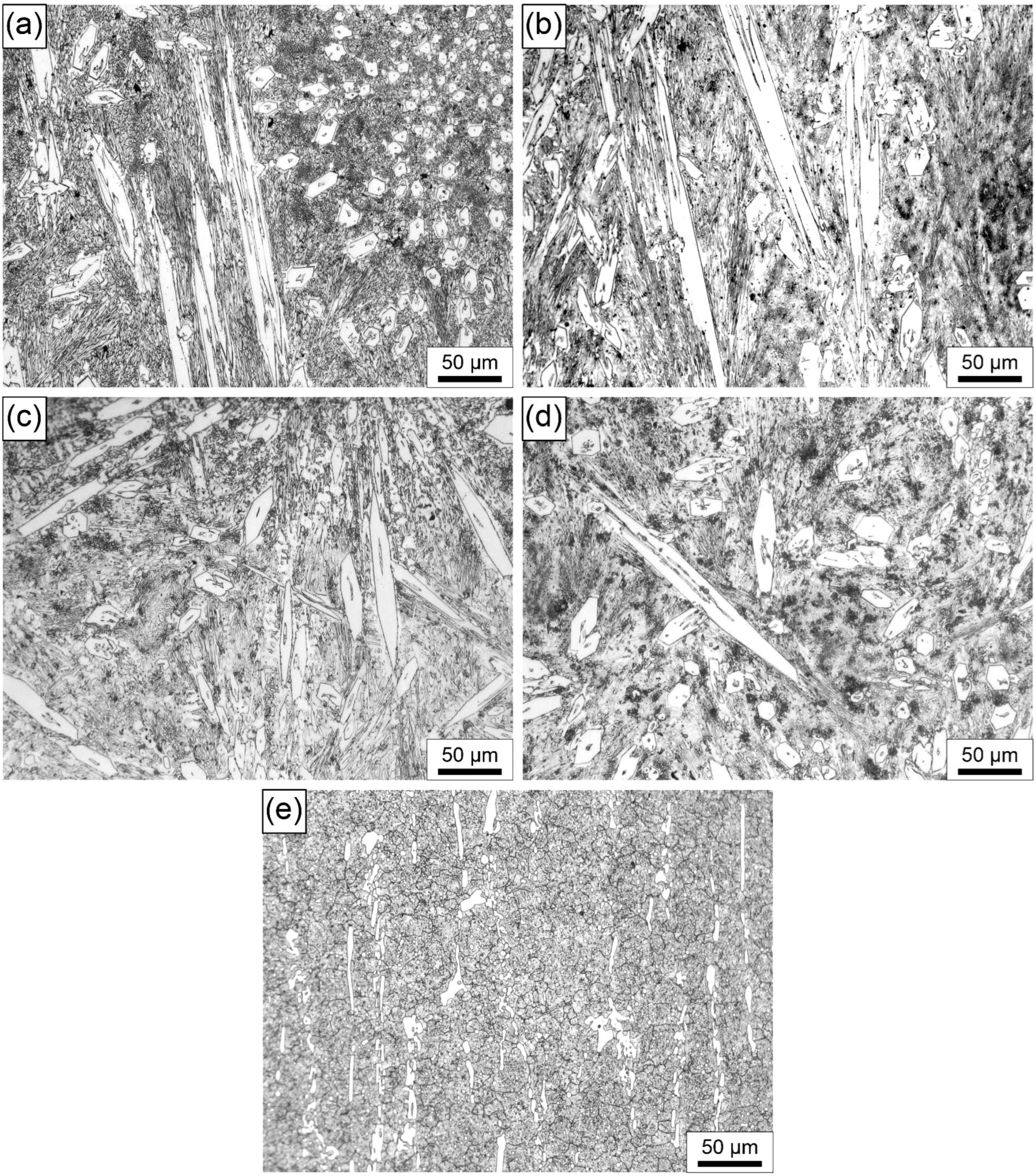
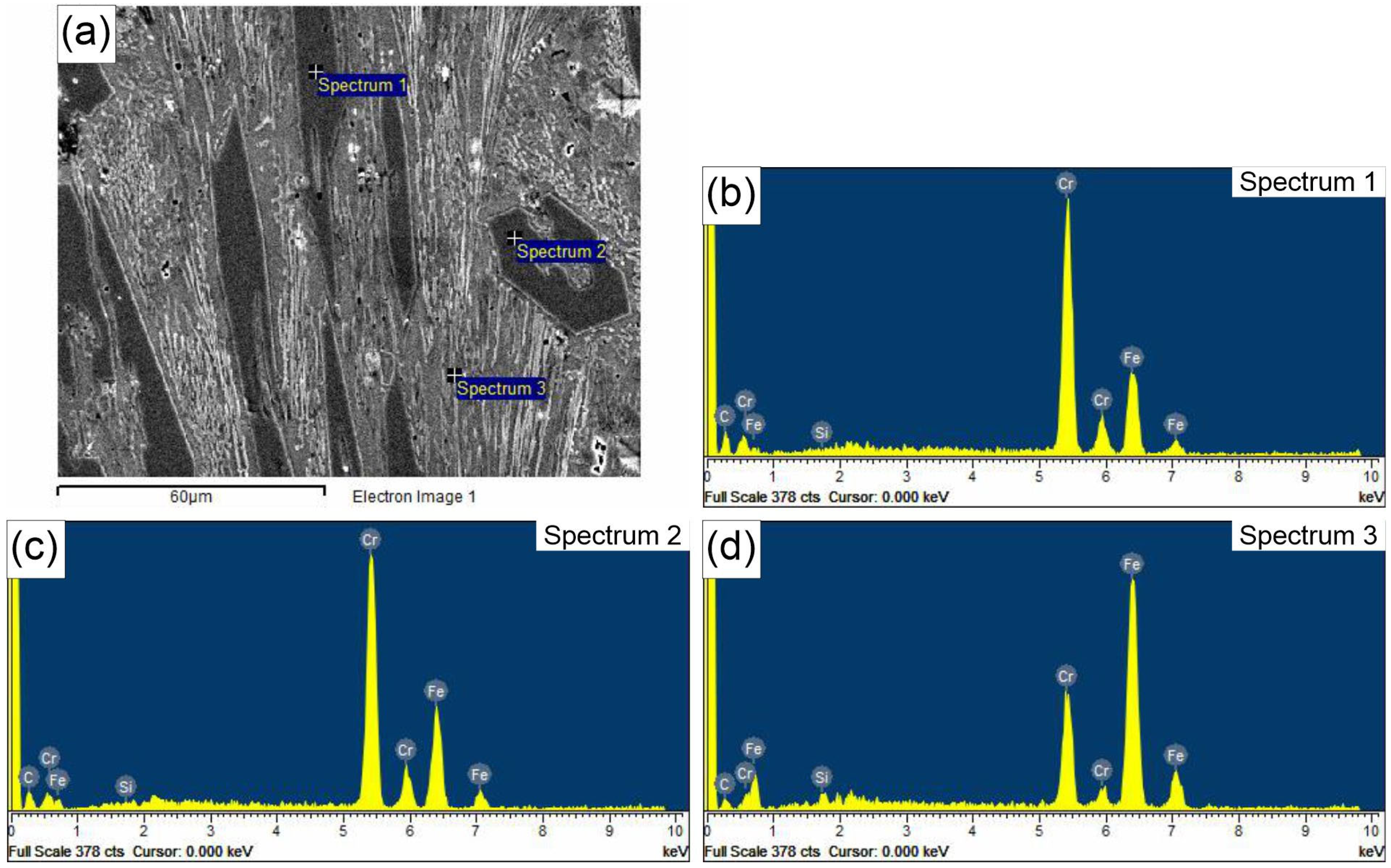
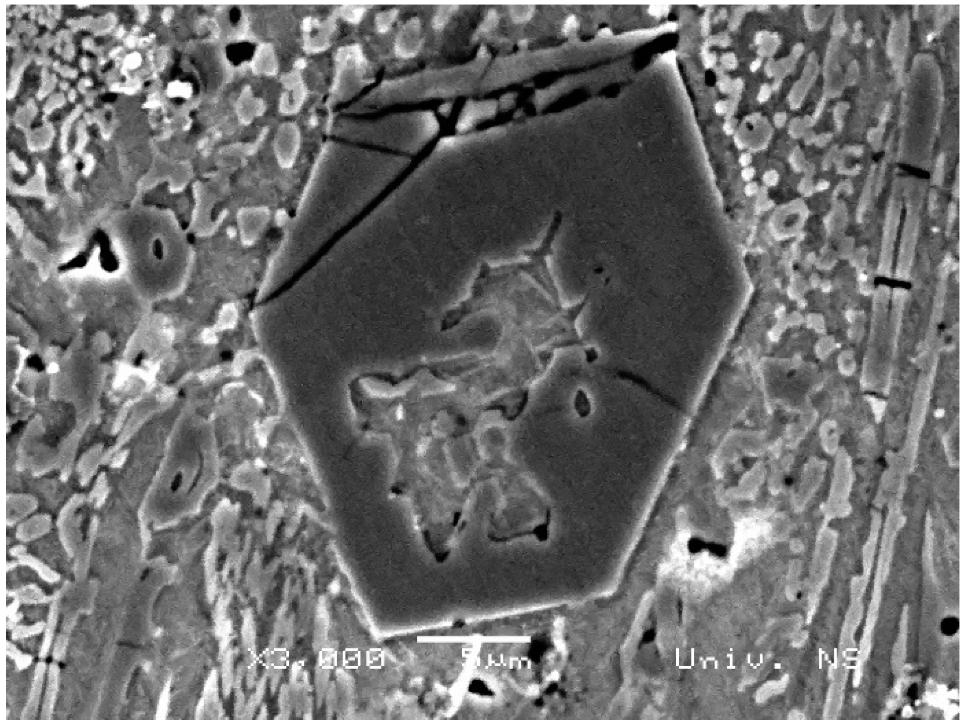
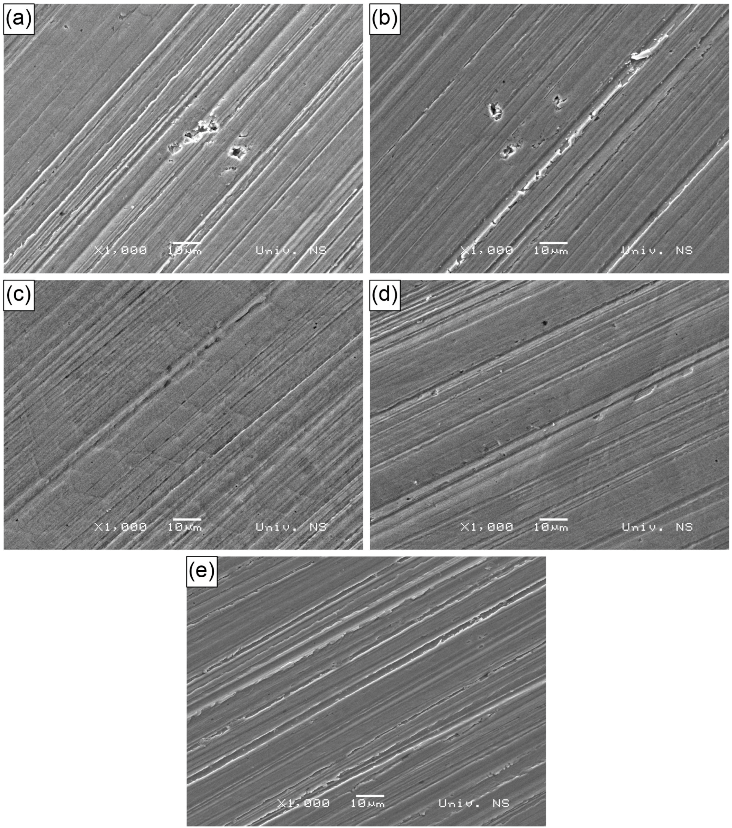
3. Results and Discussion

The microstructure of the base metal, obtained through light microscopy, is shown in Figure 1. It reveals a structure composed of ferrite and pearlite, which is characteristic of the base metal (structural steel S235JR) to which the hardfacing layer was deposited.
This section is divided into subheadings and provides a concise and precise description of the experimental results, their interpretation, and the experimental conclusions that can be drawn.
The microstructures of the subsurface finishing layer, which is critical for wear resistance, are presented in Figure 2. The light microscope analysis reveals a similarly shaped white phase, with an approximately hexagonal cross-section and elongated morphology. The growth of these phases, believed to be M7C3 carbides, occurs in various directions, forming star-shaped formations. Hardfacing alloys of the Fe-Cr-C type rely on large carbides to provide wear resistance. There are no significant differences in the morphology of the white phases observed in Specimens 1 to 4. However, in Specimen 4, these white phases appear larger compared to Specimens 1 to 3. This could be the result of a higher hardfacing current and a lower welding speed, which influence a higher heat input. In turn, higher heat input increases the cooling time, allowing for the more pronounced diffusion of elements like Cr and C, which combine with Fe to form larger complex M7C3 carbides ((Cr,Fe)7C3). This can be correlated with the deposit thickness and heat-affected zone, as shown in Table 3, where the deposited layer and heat-affected zone are thickest in Specimen 4. When analyzing Figure 2a–d (Specimens 1 to 4), the minimal dimension of the cross-section should be compared between specimens, as the elongated bright phases are merely a result of the cutting direction during metallographic preparation. To support this, the minimal dimensions of the carbide cross-sections were also measured and reported for Specimens 1 and 4. In Specimen 1, the average carbide dimension was 15 µm, while in Specimen 4, it was 10 µm. On the other hand, in AISI D2 cold-work tool steel (Figure 2e), the microstructure consists of M3C carbides ((Fe,Cr)3C), appearing as white strips in the tempered martensitic matrix, which is typical for heat-treated D2 steel, with the heat treatment parameters as explained in the experimental section.
In addition to light microscopy, scanning electron microscopy (SEM), specifically energy-dispersive X-ray spectroscopy (EDS), was applied to further describe the microstructures of the hardfaced layers. The results of the EDS analysis are shown in Figure 3 and Figure 4. These reveal a similar composition of primary hexagonal carbides in Specimens 1 and 4 (Spectra 1 and 2 in Figure 3 and Spectrum 2 in Specimen 4). In both specimens, there is a hollow structure within the carbide, as described by Ito et al. [28]. It is proposed that hollow primary carbides form when rapid cooling occurs due to the solidification dynamics during the hardfacing deposition process, which is the main difference between the two specimens analyzed in this work. The key difference is the lower current and welding speed in Specimen 1 compared to Specimen 4. This is evidenced by the core morphology, which is similar to the eutectic matrix consisting of austenite and fine M7C3 carbides in Specimen 1, and a composition with less Cr in the core compared to the rest of the carbide in Specimen 4 (Spectrum 1). On the other hand, Spectra 3 in Figure 3 and Figure 4 reveal the composition of the eutectic matrix, which contains significantly less Cr and more Fe, resembling the central section of the carbide. This is in agreement with the results obtained by Buytoz [29].
To further explore the properties of the hardfaced layers, the hardness and microhardness of certain phases were measured. Vickers hardness of the bulk material is shown in Table 5. It can be seen that the hardness of the hardfaced layers increases from Specimen 1 to Specimen 4, with Specimen 4 being the hardest. The bulk material hardness of the reference Specimen D2 is the lowest of all the specimens tested in this study.
Microhardness values for the carbides and eutectic matrix are given in Table 6. Although the same consumable was used, there are notable differences in microhardness, with the highest values obtained in the carbide and eutectic matrix regions of Specimen 4. In the case of M7C3 carbides, the hardness can be positively correlated with the carbide size. Larger carbides tend to exhibit slightly lower hardness compared to smaller ones, due to the possible presence of flaws, a less homogeneous structure, and a lower density of defects. However, in this study, the opposite result was observed, which can be explained by the large hollow central structure of the carbide filled with material, which is compositionally and morphologically similar to the eutectic matrix. This structure reduces the carbide’s integrity, making it less resistant to deformation. This is supported by Figure 5, which depicts a hollow hexagonal M7C3 carbide that has cracked in several places. Additionally, a matrix-like structure can be observed in the center of the carbide, which is confirmed by the EDS results presented in Figure 3.
In Specimen D2, significantly lower microhardness values for both the carbides and matrix were obtained. This is consistent with the microstructure of the matrix, which consists of tempered martensite. Furthermore, the carbides are M3C, which are not as hard as the M7C3 carbides found in the hardfaced layers. Moreover, the microhardness values of M7C3 primary carbides are approximately twice as high as those of the eutectic matrix. The carbide microhardness values for all specimens, presented in Table 6, are consistent with the results reported by Wang et al. [30].
The results of abrasive wear testing, specifically the weight loss rate, are shown in Figure 6. The data suggest that the highest abrasive wear loss rate was observed in Specimen 4. Its weight loss rate is significantly higher than that of Specimen 1, while the weight loss rates of Specimens 2 and 3 are similar. In contrast, the reference Specimen D2 exhibits a significantly lower abrasive wear loss rate compared to any of the hardfaced specimens (Specimens 1 to 4), especially Specimen 4. When compared to Specimen 4, reference Specimen D2 shows about half the weight loss rate. However, it is also evident that the standard deviation in Specimen D2 is the lowest of all the tested specimens, likely due to its relatively homogeneous microstructure, which consists mainly of tempered martensite with a smaller amount of M3C carbides. Overall, the higher abrasive wear resistance of the hardfaced specimens can primarily be attributed to the increased amount of M7C3 carbides, compared to the M3C carbides in the reference Specimen D2.
The wear results are further supported by the surface roughness parameter measurements, shown in Figure 7. Based on these results, it can be deduced that the lowest roughness parameters were obtained in Specimen 4, which also exhibited the highest abrasive wear resistance, along with the highest hardness and microhardness. In contrast, Specimen D2 displayed the opposite behavior, exhibiting the highest roughness and the lowest wear resistance. A similar trend of increased roughness compared to Specimen 4 was observed in Specimen 1, which has a similar microstructure but slightly lower hardness and microhardness. The increased surface roughness can be attributed to the cutting action of the hard SiC particles, which abrade the specimen’s surface consisting of carbides and a matrix of lower hardness.
SEM analysis of the worn surfaces is shown in Figure 8a–e. It can be seen that, in Specimens 1 and 2 (Figure 8a,b), ploughing occurs along with mild delamination and the revealing of some pores, ranging from 1 to 3 µm in size, which influence the wear resistance of these hardfaced deposits. Ploughing is a typical mechanism of abrasion. In Specimen 1, a group of craters, likely pores, can also be observed. Porosity may result from a higher cooling rate of these specimens, where the pores form due to the incomplete escape of gases from the melt. In Specimens 3 and 4, ploughing with some delamination occurs, with polygonal carbides visible on the surface. These carbides appear larger in Specimen 4 compared to Specimen 3, which is consistent with the microstructural features of the deposited materials shown in Figure 2c,d. Additionally, in Specimens 3 and 4, small dark dots are present, possibly indicative of minor pores. In all Specimens 1 to 4, areas with flattened asperities are observed. Specimen D2 exhibits more uniform and seemingly more pronounced ploughing and delamination, which is similar to the results presented in [10]. Intensive ploughing is likely the result of intensive abrasion, in accordance with the lower hardness of the material and weight loss rate results compared to Specimens 1 to 4.

4. Conclusions

The results obtained within the framework of this study, considering its limitations, may lead to the following conclusions:
  • All hardfaced specimens exhibited higher abrasive wear resistance compared to the reference specimen made of D2 heat-treated, cold-work tool steel, due to a higher number of carbides and the overall bulk hardness of the material. An additional effect comes from the higher microhardness of both M7C3 carbides and the matrix in the hardfaced layers, compared to the microhardness of M3C carbides and the martensitic matrix in D2 steel.
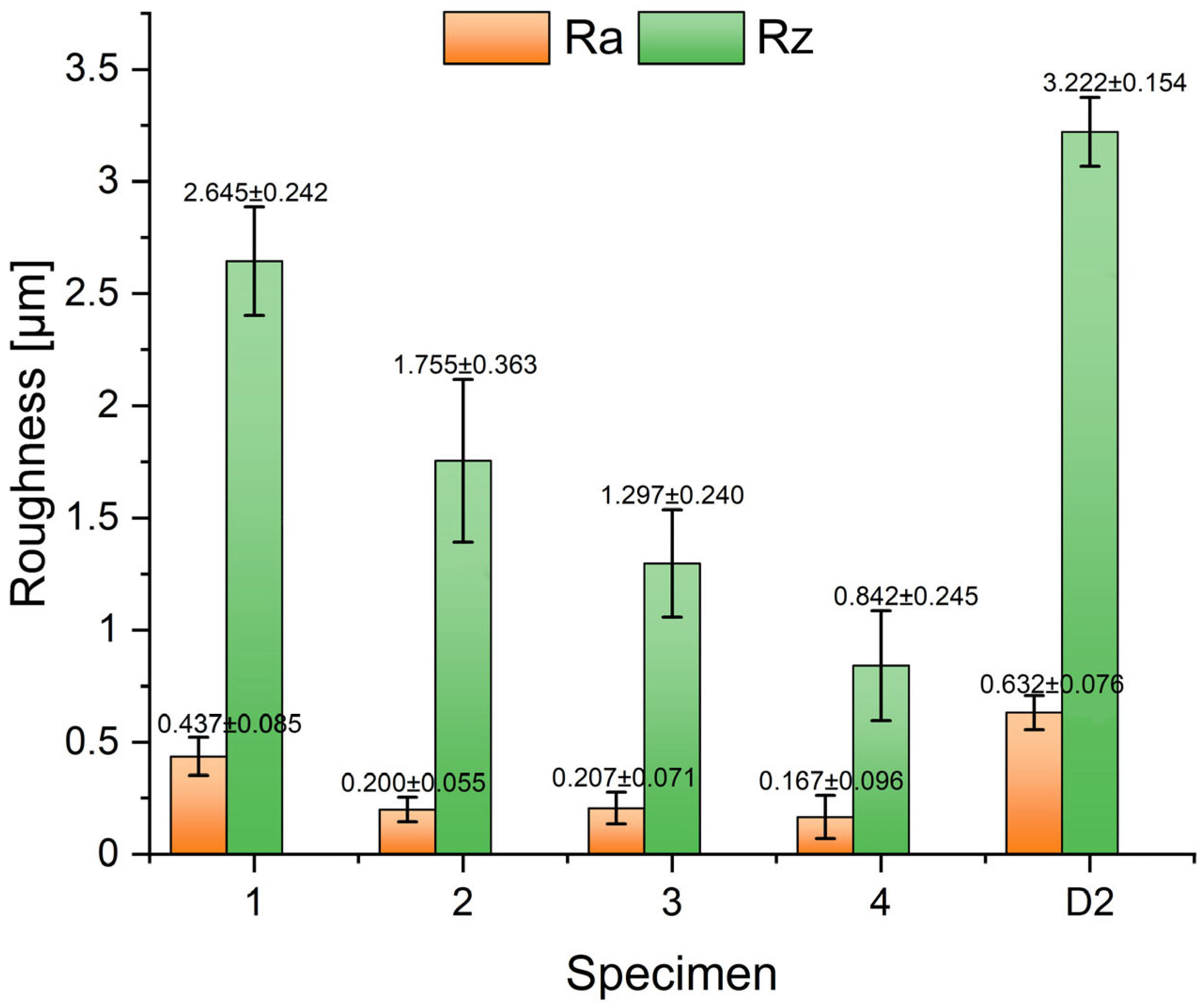
  • The specimen hardfaced with higher current and lower speed exhibited the highest abrasive wear resistance against relatively hard SiC particles, as well as the lowest roughness parameters.
  • High wear resistance is due to the relatively high microhardness of carbides, as well as a larger carbide size compared to other hardfaced specimens obtained with different parameters, i.e., a higher cooling rate.
  • Slower cooling influenced the growth of larger M7C3 carbides, with smaller central hollow sections, which exhibit a higher microhardness compared to the specimen hardfaced with lower current and higher speed (i.e., with a lower cooling time).
  • M7C3 carbides obtained with higher speed and lower current are relatively brittle and prone to cracking just after metallographic preparation, which negatively affects the wear resistance of the parent material. This section is not mandatory but can be added to the manuscript if the discussion is unusually long or complex.
  • Weight loss rate results are supported by worn surface analysis. Besides ploughing, the hardfaced specimens exhibit minor delamination and pore formation as a result of incomplete gas escape from the melt. The control specimen was worn uniformly, with intensive ploughing and delamination.
In general, for abrasive wear, hardfacing proved to be more resistant than D2 steel, while in hardfacing, a slower cooling rate—achieved with higher current and slower hardfacing speed—can be beneficial.

Author Contributions

Conceptualization and methodology, S.B. and O.E.C.; validation, S.S. and M.R.; formal analysis, M.P., P.J. and D.L.Z.; investigation, D.L.Z. and M.R.; writing—original draft preparation, S.B.; writing—review and editing, D.L.Z. and S.S.; visualization, M.P. and P.J. All authors have read and agreed to the published version of the manuscript.

Funding

This research was financially supported by the Ministry of Science, Technological Development and Innovation of the Republic of Serbia under Contract numbers 451-03-65/2024-03/200156) through the project “Scientific and Artistic Research Work of Researchers in Teaching and Associate Positions at the Faculty of Technical Sciences, University of Novi Sad” (No. 01-3394/1), 451-03-65/2024-03/200108 (Faculty of Mechanical and Civil Engineering in Kraljevo, University of Kragujevac), 451-03-66/2024-03/200213 (Innovation Centre of the Faculty of Mechanical Engineering, Belgrade, University of Belgrade), 451-03-66/2024-03/200017 through the realization of research theme 1702414 (“Vinča” Institute of Nuclear Sciences—National Institute of the Republic of Serbia, University of Belgrade).

Institutional Review Board Statement

Not applicable.

Informed Consent Statement

Not applicable.

Data Availability Statement

The original contributions presented in this study are included in the article. Further inquiries can be directed to the corresponding authors.

Acknowledgments

The authors gratefully acknowledge research support by the project entitled “Materials Science, Joining and Allied Technologies in Production Engineering” from the Department of Production Engineering, Faculty of Technical Sciences Novi Sad, Serbia. Authors owe a special gratitude to Djordje Gacesa from company Tehnoalat, Novi Sad, Serbia for providing the roughness measurement equipment.

Conflicts of Interest

The authors declare no conflicts of interest. The funders had no role in the design of the study; in the collection, analyses, or interpretation of data; in the writing of the manuscript; or in the decision to publish the results.

References

  1. Tandon, D.; Li, H.; Pan, Z.; Yu, D.; Pang, W. A Review on Hardfacing, Process Variables, Challenges, and Future Works. Metals 2023, 13, 1512. [Google Scholar] [CrossRef]
  2. Singh, R.; Pandey, S.K. Experimental Investigation of Effect of Fe-Cr-C based Hardfacing on Wear Properties of Mild Steel. Int. J. Eng. Res. Technol. (IJERT) 2016, 5, 713–716. [Google Scholar] [CrossRef]
  3. Gerard, B. Fundamentals of Hardfacing by Arc Welding; Welding Alloys: Florence, KY, USA, 2016; pp. 1–47. Available online: https://www.welding-alloys.com/wp-content/uploads/2021/12/Fundamentals_of_hardfacing_A5.pdf (accessed on 9 November 2024).
  4. Kumar, S.; Mondal, D.P.; Jha, A.K.; Khaira, H.K. Improvement in high stress abrasive wear property of steel by hardfacing. J. Mater. Eng. Perform. 1999, 8, 711–715. [Google Scholar] [CrossRef]
  5. Chakraborty, G.; Kumar, N.; Das, C.R.; Albert, S.K.; Bhaduri, A.K.; Dash, S.; Tyagi, A.K. Study on microstructure and wear properties of different nickel base hardfacing alloys deposited on austenitic stainless steel. Surf. Coat. Technol. 2014, 244, 180–188. [Google Scholar] [CrossRef]
  6. Chang, C.-M.; Chen, Y.-C.; Wu, W. Microstructural and abrasive characteristics of high carbon Fe–Cr–C hardfacing alloy. Tribol. Int. 2010, 43, 929–934. [Google Scholar] [CrossRef]
  7. Chatterjee, S.; Pal, T.K. Weld procedural effect on performance of iron basedhardfacing deposits on cast iron substrate. J. Mater. Process. Technol. 2006, 173, 61–69. [Google Scholar] [CrossRef]
  8. Balos, S.; Janjatovic, P.; Dramicanin, M.; Labus Zlatanovic, D.; Pilic, B.; Hanus, P.; Jaworska, L. Microstructure, Microhardness, and Wear Properties of Cobalt Alloy Electrodes Coated with TiO2 Nanoparticles. Metals 2019, 9, 1186. [Google Scholar] [CrossRef]
  9. Garbade, R.R.; Dhokey, N.B. Overview on Hardfacing Processes, Materials and Applications. IOP Conf. Ser. Mater. Sci. Eng. 2021, 1017, 012033. [Google Scholar] [CrossRef]
  10. Kaptanoglu, M.; Eroglu, M. Investigation of Hardfacing Deposits Obtained by Using Submerged Arc Welding Fluxes Containing High-Carbon Ferrochromium and Ferroboron. Arch. Metall. Mater. 2023, 68, 895–905. [Google Scholar] [CrossRef]
  11. Correa, E.O.; Alcântara, N.G.; Valeriano, L.C.; Barbedo, N.D.; Chaves, R.R. The effect of microstructure on abrasive wear of a Fe–Cr–C–Nb hardfacing alloy deposited by the open arc welding process. Surf. Coat. Technol. 2015, 276, 479–484. [Google Scholar] [CrossRef]
  12. Morsy, M.; El-Kashif, E. The effect of microstructure on high-stress abrasion resistance of Fe-Cr-C hardfacing deposits. Zavar. I Zavarene Konstr. 2014, 3, 119–129. [Google Scholar] [CrossRef]
  13. Rajkumar, V.; Arjunan, T.V.; Rajesh Kannan, A. Metallurgical and mechanical investigations of Inconel 625 overlay welds produced by GMAW-hardfacing process on AISI 347 pipes. Mater. Res. Express 2019, 6, 076534. [Google Scholar] [CrossRef]
  14. Abed, H.; Malek Ghaini, F.; Shahverdi, H.R. Characterization of Fe49Cr18Mo7B16C4Nb6 high-entropy hardfacing layers produced by gas tungsten arc welding (GTAW) process. Surf. Coat. Technol. 2018, 352, 360–369. [Google Scholar] [CrossRef]
  15. Ahn, D.-G. Hardfacing technologies for improvement of wear characteristics of hot working tools: A Review. Int. J. Precis. Eng. Manuf. 2013, 14, 1271–1283. [Google Scholar] [CrossRef]
  16. Liyanage, T.; Fisher, G.; Gerlich, A.P. Microstructures and abrasive wear performance of PTAW deposited Ni–WC overlays using different Ni-alloy chemistries. Wear 2012, 274–275, 345–354. [Google Scholar] [CrossRef]
  17. Hou, Q.Y. Influence of molybdenum on the microstructure and properties of a FeCrBSi alloy coating deposited by plasma transferred arc hardfacing. Surf. Coat. Technol. 2013, 225, 11–20. [Google Scholar] [CrossRef]
  18. Yao, J.; Ding, Y.; Liu, R.; Zhang, Q.; Wang, L. Wear and corrosion performance of laser-clad low-carbon high-molybdenum Stellite alloys. Opt. Laser Technol. 2018, 107, 32–45. [Google Scholar] [CrossRef]
  19. Balakrishnan, M.; Balasubramanian, V.; Madhusudhan Reddy, G. Effect of Hardfacing Processes on Ballistic Performance of Q&T Steel Joints. Mater. Perform. Charact. 2014, 3, 265–284. [Google Scholar] [CrossRef]
  20. Babu, S.; Balasubramanian, V.; Madhusudhan Reddy, G.; Balasubramanian, T.S. Improving the ballistic immunity of armour steel weldments by plasma transferred arc (PTA) hardfacing. Mater. Des. 2010, 31, 2664–2669. [Google Scholar] [CrossRef]
  21. Venkatesh, B.; Sriker, K.; Prabhakar, V.S.V. Wear Characteristics of Hardfacing Alloys: State-of-the-art. Procedia Mater. Sci. 2015, 10, 527–532. [Google Scholar] [CrossRef]
  22. Digambar, B.; Choudhary, D. A review paper on hardfacing processes, materials, objectives and applications. Int. J. Sci. Res. 2014, 3, 2400–2402. [Google Scholar]
  23. Grilli, M.L.; Valerini, D.; Slobozeanu, A.E.; Postolnyi, B.O.; Balos, S.; Rizzo, A.; Piticescu, R.R. Critical Raw Materials Saving by Protective Coatings under Extreme Conditions: A Review of Last Trends in Alloys and Coatings for Aerospace Engine Applications. Materials 2021, 14, 1656. [Google Scholar] [CrossRef] [PubMed]
  24. Regulation (EU) 2024/1252 of the European Parliament and of the Council of 11 April 2024 Establishing a Framework for Ensuring a Secure and Sustainable Supply of Critical Raw Materials and Amending Regulations (EU) No 168/2013, (EU) 2018/858, (EU) 2018/1724 and (EU) 2019/1020; European Commission: Brussels, Belgium, 2023.
  25. Stubbington, P. Hardfacing Alloy Design Consumable Review; Lincoln Electric: Padstow, NSW, Australia, 2021. [Google Scholar]
  26. Berns, H.; Fischer, A. Microstructure of Fe-Cr-C Hardfacing Alloys with Additions of Nb, Ti and B. Metallography 1987, 20, 401–429. [Google Scholar] [CrossRef]
  27. Hobart Filler Metals Application Department. Hardfacing Technical Welding Guide; Hobart Brothers, LLC.: Troy, OH, USA, 2020. [Google Scholar]
  28. Ito, S.; Kawai, H.; Oishi, Y.; Nogami, H. Structure and Solidification Process Observation of Fe-C-Cr Alloy Using Confocal Laser Scanning Microscope. MATEC Web Conf. 2021, 333, 11001. [Google Scholar] [CrossRef]
  29. Buytoz, S. Microstructural properties of M7C3 eutectic carbides in a Fe–Cr–C alloy. Mater. Lett. 2006, 60, 605–608. [Google Scholar] [CrossRef]
  30. Wang, J.; Xing, X.; Zhou, Y.; Liu, S.; Qi, X.; Yang, Q. Formation mechanism of ultrafine M7C3 carbide in a hypereutectic Fe-25Cr-4C-0.5Ti-0.5Nb-0.2N-2LaAlO3 hardfacing alloy layer. J. Mater. Res. Technol. 2020, 9, 7711–7720. [Google Scholar] [CrossRef]
Figure 1. Microstructure of base metal in the form of S235JR structural steel using light microscopy (LM).
Materials 18 00299 g001
Figure 2. LM images of microstructure of the final layer: (a) Specimen 1; (b) Specimen 2; (c) Specimen 3; (d) Specimen 4; (e) Specimen D2.
Materials 18 00299 g002
Figure 3. (a) SEM micrograph of Specimen 1 EDS spectra of the carbide particles and the eutectic matrix; (b) Spectrum 1; (c) Spectrum 2; (d) Spectrum 3.
Materials 18 00299 g003
Figure 4. (a) SEM micrograph of Specimen 4 EDS spectra of the carbide particles and the eutectic matrix; (b) Spectrum 1; (c) Spectrum 2; (d) Spectrum 3.
Materials 18 00299 g004
Figure 5. SEM micrograph of cracked M7C3 carbide in Specimen 1.
Materials 18 00299 g005
Figure 6. Weight loss rate of tested specimens.
Materials 18 00299 g006
Figure 7. Roughness parameters Ra and Rz for wear tested specimens.
Materials 18 00299 g007
Figure 8. Worn surfaces: (a) Specimen 1; (b) Specimen 2; (c) Specimen 3; (d) Specimen 4; (e) Specimen D2.
Materials 18 00299 g008
Table 1. Chemical composition of S235JR (wt.%).
CSiMnSCrPCuNiFe
0.150.180.740.0350.020.020.020.05Balance
Table 2. Nominal chemical composition of E Fe14 electrode (wt.%).
CSiCrFe
3.01.329.0Balance
Table 3. Hardfacing parameters for Specimens 1 to 4 (electrode E Fe14).
Specimen 1Specimen 2Specimen 3Specimen 4
Electrode diameter × lengthØ3.2 × 320 mm
Arc voltage [V]25252424
Welding current [A]9595115115
Current typeDC+
Welding speed [cm/min]14121412
PreheatingNo
Electrode inclination towards horizontal [°]80
Deposit thickness range [mm]5.5–66.5–76.5–77–7.2
Heat affected zone [mm]1–1.21.4–1.81.2–1.61.6–1.8
Table 4. Chemical composition of the AISI D2 cold-work tool steel (wt.%).
CSiMnSCrPNiMoVCoFe
1.560.460.340.00412.810.0240.170.970.900.021Balance
Table 5. HV30 hardness of the hardfaced layers and reference AISI D2 steel [kgf/mm2].
Specimen 1Specimen 2Specimen 3Specimen 4D2
Average values663 ± 12707 ± 8712 ± 13730 ± 6640 ± 12
Table 6. HV0.01 microhardness of phases within the hardfaced layers [kgf/mm2].
Specimen 1Specimen 2Specimen 3Specimen 4D2
Carbides, average values1601.9 ± 54.21683.9 ± 79.61735.2 ± 128.61837.4 ± 49.41052.4 ± 64.3
Matrix, average values851.7 ± 61.8910.8 ± 80.9952.1 ± 121.0997.4 ± 52.6670.6 ± 50.6
Disclaimer/Publisher’s Note: The statements, opinions and data contained in all publications are solely those of the individual author(s) and contributor(s) and not of MDPI and/or the editor(s). MDPI and/or the editor(s) disclaim responsibility for any injury to people or property resulting from any ideas, methods, instructions or products referred to in the content.

