
Effects of Ar Ion Irradiation on Mechanical Properties and Microstructure of SA508 Grade 3 Class 1 and Class 2 Reactor Pressure Vessel Steels

Highlights
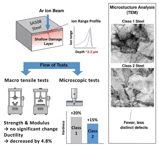
- Ar ion irradiation creates shallow damage (~2.2 µm) in SA508 reactor vessel steels.
- Macro-mechanical tests show no hardening due to limited damaged volume fraction.
- Nanoindentation reveals clear hardening: a 20% increase in Class 1 and a 15% increase in Class 2.
- TEM confirms higher defect density in Class 1 than Class 2 after irradiation.
- Ion irradiation creates dislocation loops which reduce metal ductility at low doses.
Abstract
1. Introduction
2. Experimental Methods
2.1. Materials
2.2. Ar Ion Irradiation
2.3. Mechanical Testing
2.4. Microstructural Analysis
3. Results
3.1. SRIM/TRIM Simulation Results
3.2. Macro-Scale Mechanical Test Results
3.3. Nanoindentation Test Results
3.4. TEM Microstructural Analysis
4. Discussion
5. Conclusions
Author Contributions
Funding
Data Availability Statement
Conflicts of Interest
References
- Hashmi, M.F.; Wu, S.J.; Li, H.X. Neutron Irradiation Embrittlement Modeling in RPV Steels—An Overview. In Proceedings of the International Conference on Nuclear Engineering, Toronto, ON, Canada, 17–20 July 2005. [Google Scholar]
- Was, G.S.; Jiao, Z.; Getto, E.; Sun, K.; Monterrosa, A.M.; Maloy, S.A.; Anderoglu, O.; Sencer, B.H.; Hackett, M. Emulation of Reactor Irradiation Damage Using Ion Beams. Scr. Mater. 2014, 88, 33–36. [Google Scholar] [CrossRef]
- Zhou, L.; Dai, J.; Li, Y.; Dai, X.; Xie, C.; Li, L.; Chen, L. Research Progress of Steels for Nuclear Reactor Pressure Vessels. Materials 2022, 15, 8761. [Google Scholar] [CrossRef]
- Taller, S.; VanCoevering, G.; Wirth, B.D.; Was, G.S. Predicting Structural Material Degradation in Advanced Nuclear Reactors with Ion Irradiation. Sci. Rep. 2021, 11, 2949. [Google Scholar] [CrossRef]
- Saha, U.; Devan, K.; Ganesan, S. A Study to Compute Integrated Dpa for Neutron and Ion Irradiation Environments Using SRIM-2013. J. Nucl. Mater. 2018, 503, 30–41. [Google Scholar] [CrossRef]
- I-SMR. Available online: https://i-smrkr.com/ (accessed on 19 August 2025).
- Innovative Small Modular Reactor Development Agency. Available online: https://ismr.or.kr/eng/sub/innovation (accessed on 19 August 2025).
- Stoller, R.E. Radiation Damage Correlation; Springer: Berlin, Germany, 2020. [Google Scholar]
- Parrish, R.; Hattar, K.M.; Barr, C.M.; Tucker, G.; Gupta, A. TEM Comparison of Neutron and Ion Beam Damage in Nanocrystalline Gold; Technical Report SAND2020-4567; Sandia National Laboratories: Albuquerque, NM, USA, 2020. [Google Scholar]
- Moschetti, M.; Xu, A.; Schuh, B.; Hohenwarter, A.; Couzinié, J.-P.; Kruzic, J.J.; Bhattacharyya, D.; Gludovatz, B. On the Room-Temperature Mechanical Properties of an Ion-Irradiated TiZrNbHfTa Refractory High Entropy Alloy. JOM 2020, 72, 130–138. [Google Scholar] [CrossRef]
- Titze, M.; Pacheco, J.L.; Byers, T.; Van Deusen, S.B.; Perry, D.L.; Weathers, D.; Bielejec, E.S. Evaluation of the Accuracy of Stopping and Range of Ions in Matter Simulations through Secondary Ion Mass Spectrometry and Rutherford Backscattering Spectrometry for Low Energy Heavy Ion Implantation. J. Vac. Sci. Technol. A 2021, 39, 063222. [Google Scholar] [CrossRef]
- James Ziegler—SRIM & TRIM. Available online: http://www.srim.org/ (accessed on 19 August 2025).
- Lloyd, M.J.; Haley, J.; Jim, B.; Abernethy, R.; Gilbert, M.R.; Martinez, E.; Hattar, K.; El-Atwani, O.; Nguyen-Manh, D.; Moody, M.P.; et al. Microstructural Evolution and Transmutation in Tungsten under Ion and Neutron Irradiation. Materialia 2024, 33, 101991. [Google Scholar] [CrossRef]
- Röder, F.; Heintze, C.; Pecko, S.; Akhmadaliev, S.; Bergner, F.; Ulbricht, A.; Altstadt, E. Nanoindentation of Ion-Irradiated Reactor Pressure Vessel Steels—Model-Based Interpretation and Comparison with Neutron Irradiation. Philos. Mag. 2018, 98, 911–933. [Google Scholar] [CrossRef]
- Hosemann, P.; Shin, C.; Kiener, D. Small Scale Mechanical Testing of Irradiated Materials. J. Mater. Res. 2015, 30, 1231–1245. [Google Scholar] [CrossRef]
- Prasitthipayong, A.; Frazer, D.; Kareer, A.; Abad, M.D.; Garner, A.; Joni, B.; Ungar, T.; Ribarik, G.; Preuss, M.; Balogh, L.; et al. Micro Mechanical Testing of Candidate Structural Alloys for Gen-IV Nuclear Reactors. Nucl. Mater. Energy 2018, 16, 34–45. [Google Scholar] [CrossRef]
- Sadeghilaridjani, M.; Ayyagari, A.; Muskeri, S.; Hasannaeimi, V.; Jiang, J.; Mukherjee, S. Small-Scale Mechanical Behavior of Ion-Irradiated Bulk Metallic Glass. JOM 2020, 72, 123–129. [Google Scholar] [CrossRef]
- Hasenhuetl, E.; Kasada, R.; Zhang, Z.; Yabuuchi, K.; Kimura, A. Ion-Irradiation Effect on Strain Rate Sensitivity of Nanoindentation Hardness of W Single Crystal. Mater. Trans. 2017, 58, 580–586. [Google Scholar] [CrossRef]
- Xiao, X.; Yu, L. Nano-Indentation of Ion-Irradiated Nuclear Structural Materials: A Review. Nucl. Mater. Energy 2020, 22, 100721. [Google Scholar] [CrossRef]
- American Society of Mechanical Engineers. ASME B&PV Code Section II, Part A: Ferrous Materials; American Society of Mechanical Engineers: New York, NY, USA, 2019. [Google Scholar]
- Yang, Y.; Li, J.; Zhang, C. The Investigation of the Carbon on Irradiation Hardening and Defect Clustering in RPV Model Alloy Using Ion Irradiation and OKMC Simulation. Nucl. Eng. Technol. 2024, 56, 2071–2078. [Google Scholar] [CrossRef]
- ISO 148-1:2016; Metallic Materials—Charpy Pendulum Impact Test—Part 1: Test Method. International Organization for Standardization: Geneva, Switzerland, 2016.
- Kasada, R.; Konishi, S.; Yabuuchi, K.; Nogami, S.; Ando, M.; Hamaguchi, D.; Tanigawa, H. Depth-Dependent Nanoindentation Hardness of Reduced-Activation Ferritic Steels after MeV Fe-Ion Irradiation. Fusion Eng. Des. 2014, 89, 1637–1641. [Google Scholar] [CrossRef]
- Nix, W.D.; Gao, H. Indentation Size Effects in Crystalline Materials: A Law for Strain Gradient Plasticity. J. Mech. Phys. Solids 1998, 46, 411–425. [Google Scholar] [CrossRef]
- Westbrook, J.H.; Conrad, H. The Science of Hardness Testing and Its Research Applications; American Society for Metals: Metals Park, OH, USA, 1973. [Google Scholar]
- Oliver, W.C.; Pharr, G.M. An Improved Technique for Determining Hardness and Elastic Modulus Using Load and Displacement Sensing Indentation Experiments. J. Mater. Res. 1992, 7, 1564–1583. [Google Scholar] [CrossRef]
- Yu, K.Y.; Fan, C.; Chen, Y.; Li, J.; Zhang, X. Recent Studies on the Microstructural Response of Nanotwinned Metals to In Situ Heavy Ion Irradiation. JOM 2020, 72, 160–169. [Google Scholar] [CrossRef]
- Derby, B.K.; Baldwin, J.K.; Chen, D.; Demkowicz, M.J.; Wang, Y.Q.; Misra, A.; Li, N. Faceted He-Filled “Pancakes” Confined within Nanoscale Metal Layers. JOM 2020, 72, 145–149. [Google Scholar] [CrossRef]
- Sun, C.; Müller, E.; Meffert, M.; Gerthsen, D. Analysis of Crystal Defects by Scanning Transmission Electron Microscopy (STEM) in a Modern Scanning Electron Microscope. Adv. Struct. Chem. Imaging 2019, 5, 1. [Google Scholar] [CrossRef]
- Lin, Y.-R.; Li, Y.; Zinkle, S.J.; Arregui-Mena, J.D.; Burke, M.G. Application of Weak-Beam Dark-Field STEM for Dislocation Loop Analysis. Microsc. Microanal. 2024, 30, ozae067. [Google Scholar] [CrossRef]
- Du, Y.; Yoshida, K.; Shimada, Y.; Toyama, T.; Inoue, K.; Arakawa, K.; Suzudo, T.; Milan, K.J.; Gerard, R.; Ohnuki, S.; et al. In-Situ WB-STEM Observation of Dislocation Loop Behavior in Reactor Pressure Vessel Steel during Post-Irradiation Annealing. Materialia 2020, 12, 100778. [Google Scholar] [CrossRef]
- Ambat, M.V.; Frazer, D.; Popovic, M.P.; Balooch, M.; Stevenson, S.; Scott, A.; Kabel, J.; Hosemann, P. Localized Helium Implantation in SiCf/SiCm Composites Comparing Fiber and Matrix Swelling. JOM 2020, 72, 170–175. [Google Scholar] [CrossRef]
- Brázda, P.; Klementová, M.; Krysiak, Y.; Palatinus, L. Accurate Lattice Parameters from 3D Electron Diffraction Data. I. Optical Distortions. IUCrJ 2022, 9, 735–755. [Google Scholar] [CrossRef]
- Weirich, T.E.; Zou, X.; Ramlau, R.; Simon, A.; Cascarano, G.L.; Giacovazzo, C.; Hovmöller, S. Structures of Nanometre-Size Crystals Determined from Selected-Area Electron Diffraction Data. Acta Crystallogr. Sect. A 2000, 56, 29–35. [Google Scholar] [CrossRef]
- Sahoo, P.K.; Mohanty, T.; Kanjilal, D.; Pradhan, A.; Kulkarni, V.N. Epitaxial Recrystallization of Amorphous Si Layers by Swift Heavy Ions. Nucl. Instrum. Methods Phys. Res. B 2007, 257, 244–248. [Google Scholar] [CrossRef]
- Zinkle, S.J.; Was, G.S. Materials Challenges in Nuclear Energy. Acta Mater. 2013, 61, 735–758. [Google Scholar] [CrossRef]
- Odette, G.R.; Lucas, G.E. Embrittlement of Nuclear Reactor Pressure Vessels. JOM 2001, 53, 18–22. [Google Scholar] [CrossRef]
- Ma, H.; Fan, P.; Qian, Q.; Zhang, Q.; Li, K.; Zhu, S.; Yuan, D. Nanoindentation Test of Ion-Irradiated Materials: Issues, Modeling and Challenges. Materials 2024, 17, 3286. [Google Scholar] [CrossRef]
- Symposium on Internal Stresses in Metals and Alloys. Nature 1949, 164, 296. [CrossRef]


Disclaimer/Publisher’s Note: The statements, opinions and data contained in all publications are solely those of the individual author(s) and contributor(s) and not of MDPI and/or the editor(s). MDPI and/or the editor(s) disclaim responsibility for any injury to people or property resulting from any ideas, methods, instructions or products referred to in the content. |
© 2025 by the authors. Licensee MDPI, Basel, Switzerland. This article is an open access article distributed under the terms and conditions of the Creative Commons Attribution (CC BY) license (https://creativecommons.org/licenses/by/4.0/).
Share and Cite
Kim, H.-A.; Kim, M.; Choi, S.; Kim, S. Effects of Ar Ion Irradiation on Mechanical Properties and Microstructure of SA508 Grade 3 Class 1 and Class 2 Reactor Pressure Vessel Steels. Materials 2025, 18, 4601. https://doi.org/10.3390/ma18194601
Kim H-A, Kim M, Choi S, Kim S. Effects of Ar Ion Irradiation on Mechanical Properties and Microstructure of SA508 Grade 3 Class 1 and Class 2 Reactor Pressure Vessel Steels. Materials. 2025; 18(19):4601. https://doi.org/10.3390/ma18194601
Chicago/Turabian StyleKim, Ho-A, Mincheol Kim, Sungjun Choi, and Sangtae Kim. 2025. "Effects of Ar Ion Irradiation on Mechanical Properties and Microstructure of SA508 Grade 3 Class 1 and Class 2 Reactor Pressure Vessel Steels" Materials 18, no. 19: 4601. https://doi.org/10.3390/ma18194601
APA StyleKim, H.-A., Kim, M., Choi, S., & Kim, S. (2025). Effects of Ar Ion Irradiation on Mechanical Properties and Microstructure of SA508 Grade 3 Class 1 and Class 2 Reactor Pressure Vessel Steels. Materials, 18(19), 4601. https://doi.org/10.3390/ma18194601