Highlights
- Coil-gap optimization for superconducting magnetic energy storage (SMES) magnets.
- Adaptive genetic algorithm for SMES magnet optimization.
- Multi-solenoid parallel configuration for high-critical-current operation.
Abstract
Advanced energy storage solutions are required to mitigate grid destabilization caused by high-penetration renewable energy integration. Superconducting Magnetic Energy Storage (SMES) offers ultrafast response (<1 ms), high efficiency (>95%), and almost unlimited cycling life. However, its commercialization is hindered by the complex modeling of critical current with anisotropic behaviors and the computational inefficiency of high-dimensional optimization for megajoule (MJ)-class magnets. This paper proposes an integrated design framework synergizing a two-dimensional axisymmetric magnetic field model based on Conway’s current-sheet theory, a critical current anisotropy characterization model, and an adaptive genetic algorithm (AGA). A superconducting magnet optimization model incorporating co-calculation of electromagnetic parameters is established. A dual-module chromosome encoding strategy (discrete gap index + nonlinear increment) and parallel acceleration techniques were developed. This approach achieved efficient optimization of MJ-class magnets. For a single solenoid, the critical current increased by 22.6% (915 A) and energy storage capacity grew by 41.8% (1.12 MJ). A 20-unit array optimized by coordinated gap adjustment achieved a matched inductance/current of 0.15 H/827 A (20 MJ), which can enhance transient stability control capability in smart grids. The proposed method provides a computationally efficient design paradigm and user-friendly teaching software tool for high-current SMES magnets, supporting the development of large-scale High-Temperature Superconducting (HTS) magnets, promoting the deployment of large-scale HTS magnets in smart grids and high-field applications.
1. Introduction
The high-penetration integration of renewable energy sources exacerbates dynamic instability in modern power systems. The large-scale integration of intermittent energy sources like wind and photovoltaics intensifies grid fluctuations [1]. Conventional energy storage technologies are constrained by response speed (e.g., battery response time ~100 ms) and cycle life (typically below 10,000 cycles) [2], making them inadequate for millisecond-level power quality management requirements. Superconducting Magnetic Energy Storage (SMES), with its ultrafast response (<1 ms), ultra-high efficiency (>95%) [3], and almost infinite charge/discharge cycle life, emerges as an ideal solution for suppressing grid transient disturbances [4].
However, the capital cost of superconducting energy storage magnets is relatively high. It is necessary to optimize the design of their internal magnet structure to obtain the targeted energy storage capacity and current rating required by the power grid at the lowest economic cost. The energy storage capacity of a magnet is directly proportional to its inductance and the square of the critical current.
Due to the anisotropy of superconductors, the critical current degradation rate of REBCO tapes under perpendicular magnetic fields can be several times higher than under parallel fields [5,6]. Traditional design methods attempt to accurately quantify the coupled influence of the magnetic field vector on critical current [7]. Multi-parameter co-optimization of MJ-class magnets constitutes a high-dimensional nonlinear constrained problem [8]. While the Finite Element Method (FEM) offers high accuracy, a single full-parameter simulation can take several hours, rendering it impractical for iterative optimization. Although Simulated Annealing (SA) has been applied to magnet structural optimization, its convergence efficiency is low, and engineering adaptability is weak [9].
For the analytical optimization solutions, Conway’s analytical method for rectangular cross-section coil fields laid the foundation for efficient field computation, but this model did not incorporate the anisotropic properties of superconducting materials [10]; Hajiri et al. introduced an electromagnetic-thermal finite element model coupled to a reduced electrical circuit to simulate quench propagation in inductive HTS coils under overcurrent regimes. By incorporating flux-flow resistance and contact resistance effects, the model enhances quench prediction accuracy; however, it is limited to single-coil analysis and ignores material anisotropy in current distribution [11]. Li et al. focused on AC loss optimization in HTS SMES integrated with hydrogen-battery hybrid systems. Their work synergizes energy management strategies with magnet AC loss reduction, improving system-level efficiency, but relies on simplified axisymmetric models that cannot accurately capture 3D fringe fields and omits mechanical stress effects on critical current degradation [12]. Notably, Xue et al. pioneered a large-scale GPU-optimized algorithm to resolve coupled electromagnetic-thermal-strain dynamics during quenching in multifilamentary Nb3Sn coils. Their model uncovered the correlation between instability propagation velocity and cumulative Joule heating (rather than instantaneous power), offering key insights for magnet design. However, this framework remains restricted to Nb3Sn materials and does not address the critical current anisotropy inherent in REBCO tapes [13]. These limitations result in existing magnets having low energy density and insufficient tape utilization, severely constraining the economic viability of SMES magnets.
Large-scale superconducting magnet systems (such as the ITER Tokamak [14], CERN’s Large Hadron Collider (LHC) [15], and China Southern Power Grid’s 10 MJ SMES demonstration project [16]) have comprehensively addressed engineering feasibility issues in their designs. These projects have employed advanced technologies such as forced-flow helium cooling, improved mechanical support, and active quench protection system combining energy extraction and segmentation. For instance, the ITER project utilizes large toroidal magnet systems with carefully designed mechanical support structures to cope with enormous Lorentz forces and employs multi-level protection systems to ensure safe operation. Similarly, LHC’s superconducting rings employ distributed cooling systems and advanced quench detection technologies to manage high energy storage capacity (approximately 700 MJ).
However, these pioneering systems were primarily optimized for their specific scientific or demonstration objectives, often prioritizing extreme performance metrics over magnet design economy and scalability. This has left a gap in systematic methodologies that simultaneously address electromagnetic performance, geometric constraints, and practical manufacturability for commercial energy storage applications.
To overcome these challenges, this article proposed a SMES magnet design methodology synergizing analytical model and intelligent algorithms. First, a two-dimensional axisymmetric magnetic field model for pancake coils was established based on Conway’s current-sheet theory, incorporating the critical current anisotropy to quantify the electro-magnetic coupling behavior. Second, targeting two Non-deterministic Polynomial-time hard problems (NP-hard problems [17]) of magnet dimensional optimization and inter-pancake gap distribution, an adaptive genetic algorithm was developed to feature dual-module chromosome encoding (discrete gap indexing + stochastic increment seeding), elite preservation strategy, adaptive mutation, and accelerated computation via vectorization and parallel processing. Furthermore, the optimized single-solenoid unit was extended to a parallel magnet array comprising multiple solenoid units, where coordinated optimization of the inter-unit gaps was implemented to achieve precise inductance matching and minimize electromagnetic coupling interference.
2. Methodology
2.1. Magnetic Field Calculation
Based on Conway’s current-sheet theory [10], a 2D analytical solution for the magnetic field generated by pancake coils is established. For a single pancake coil with inner radius Ri, outer radius Ro, and height Whts, as shown in Figure 1, the magnetic field at a point (r,z) in cylindrical coordinates can be decomposed into:
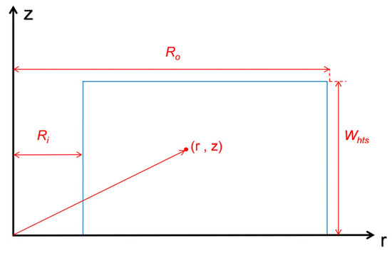
Figure 1.
Schematic diagram of a single pancake coil.
Axial component (parallel to the tape surface):
Radial component (perpendicular to the tape surface):
The simplified forms of the core functions ψ1 and ψ2 are given in Equations (3) and (4). The complete mathematical descriptions, encompassing the full set of integral terms L1 and L2, are provided in Appendix A (Equations (A1) and (A2)).
where the geometric factor is
J is the current density per unit volume, µ0 is the vacuum permeability (4π × 10−7 H m−1), and a represents |z| or |Whts − z|.
2.2. Critical Current Anisotropy Model
REBCO superconducting tapes exhibit field angle dependence in their critical current Ic [18,19]. They achieve high-current transmission in strong fields at liquid-nitrogen temperatures through heteroepitaxial integration on flexible metal substrates, nano-buffer layers [20,21], REBCO superconducting films, and Ag/Cu composite stabilizing layers [20]. The structure of the REBCO superconducting tape is shown in Figure 2. The critical current is calculated as follows:
where the effective magnetic field is:
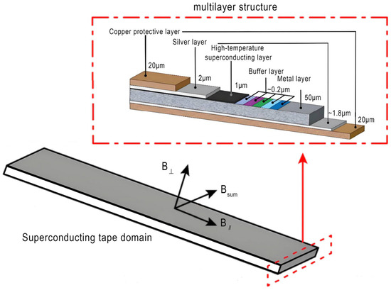
Figure 2.
Schematic diagram of REBCO superconducting tape.
Experimentally fitted parameters (20 K operation): Ic0 = 1736 A (zero-field critical current) [9,21,22,23], B1 = 1.59 T (characteristic magnetic field), = 3.38 (anisotropy ratio), α = 0.88 (decay exponent) [24,25,26]. The parameters Ic0, B1, γ, and α were adopted from experimental characterizations of commercial REBCO tapes [9,18,26,27], ensuring the model’s relevance to practical HTS magnet design. The critical current calculation flowchart is shown in Figure 3a.
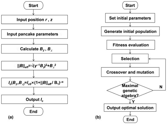
Figure 3.
Model calculation and optimization framework. (a): Critical current calculation flowchart; (b): Adaptive genetic algorithm structure.
2.3. Inductance Calculation Model
Utilizing self-inductance and mutual inductance theory [28], the self-inductance of a single pancake is calculated as follows:
where = Ro/Ri (radius ratio), hts/2Ri (form factor)
Pancake-to-pancake mutual inductance is calculated as follows [29,30]:
where Li+j is the equivalent self-inductance when pancake coils i and j are merged, Lgap denotes the inductance component contributed by the air-gap region between the two coils, Li and Lj are the self-inductances of the individual pancake coils i and j, respectively.
The total inductance of a multi-pancake system is:
where the coupling coefficient is an empirical decay factor.
2.4. Genetic Algorithm Optimization Design
For the single solenoid size optimization and single solenoid gap optimization problems, the constraints are defined as follows:
where N is the number of turns per pancake, Wturn is the equivalent single-turn width (including insulation), Lsum is the total inductance (including self and mutual inductance), Emax is the maximum energy storage capacity, q is the maximum outer radius per pancake, Ic is calculated by the anisotropic critical current model using Equation (6), and Iop is the minimum operating current requirement of the magnet.
where g is the starting gap spacing, g1 is its lower limit, g2 is its upper limit, m is the number of movable pancakes on one side, n is the total number of pancakes on one side, Ssum is the total tape length, p is the maximum allowable total tape length, and Ic,calc is the calculated critical current value.
Targeting the two NP-hard problems defined by Equation (11) (size) and Equation (12) (gaps), and considering the unknown structure of their solution space, an improved GA framework is proposed in Figure 3b and described as follows
- (1)
- Dual-Module Chromosome Encoding
Module 1 uses a discretized gap value index (10-bit gene, mapping to 1024 candidate points). Module 2 uses a random seed to control the mirror increment Δx, enabling a nonlinear distribution of gap spacings for pancakes moved on one side:
where ∈ randomly selected per calculation.
where ∈ [0, 1] ∈
- (2)
- Adaptive Mechanism
Mutation probability is dynamically adjusted based on individual fitness [31,32]: decreased for high-fitness individuals and increased for low-fitness individuals. An elitist preservation strategy maintains population diversity.
- (3)
- Acceleration Strategies
Vectorized analytical magnetic field computation, memory pre-allocation to reduce dynamic overhead, and parallel evaluation of population fitness are implemented. This approach significantly enhances the solving efficiency and accuracy of high-dimensional constrained problems by decoupling the variable space and employing intelligent encoding strategies [33].
3. Optimization Strategy and Framework
This study employed a phased optimization strategy to design a high-energy-density SMES solenoid magnet:
- (1)
- Single Solenoid Size Optimization
Under the constraints of Equation (11) (including maximum tape length Ssum, maximum pancake outer radius q, and minimum operating current Iop), with the goal of maximum energy storage capacity Emax, the key decision variables were the inner radius Ri and the number of pancakes Q. As shown in Figure 4, this step determined the optimal Ri, Ro, total height H, total pancakes Q, turns per pancake N, and the corresponding inductance Lsum and critical current Ic.
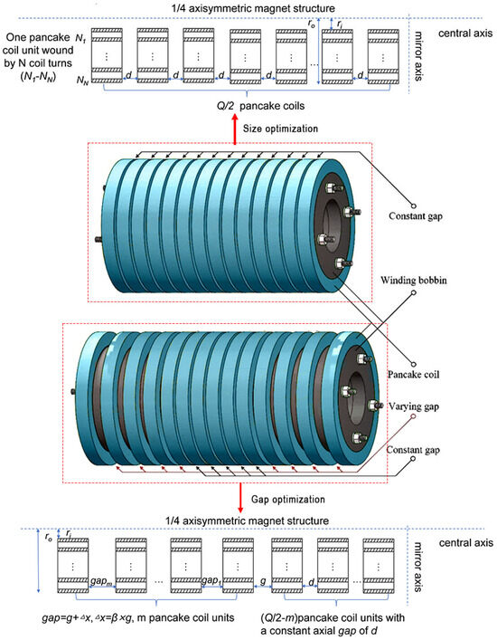
Figure 4.
Schematic diagram of single solenoid size optimization and single solenoid gap distribution optimization.
- (2)
- Single Solenoid Gap Distribution Optimization
Based on the optimized configuration from Step 1, under the constraints of Equation (12) (including number of movable pancakes per side m, gap spacing g), gap distribution optimization is carried out. As shown in Figure 4, the two variables were m and g. A specific encoding strategy searched for the optimal gap to further enhance Emax. The output results include the optimal m, gap sequence, inductance L, critical current Ic, and tape usage S.
- (3)
- Multi-Solenoid Parallel Array
Based on the optimized single-solenoid unit derived from the above two steps, a parallel array comprising multiple units is constructed to achieve the targeted energy storage capacity. This step involves the coordinated optimization of horizontal and vertical inter-unit gaps. This step involves the coordinated optimization of the inter-unit gaps in the x-direction (g1) and y-direction (g2). The primary objective is to maximize the system’s energy storage capacity while rigorously ensuring the convergence of the total inductance to a specified value, thereby establishing a comprehensive design framework for large-scale SMES magnets characterized by low coupling interference. Figure 5 is a schematic diagram of multi-solenoid parallel array.
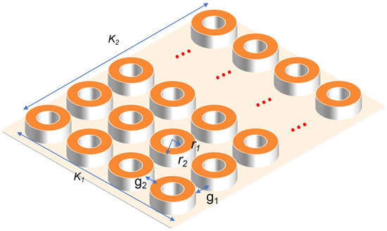
Figure 5.
Schematic diagram of multi-solenoid parallel array.
4. Optimization of the Single-Solenoid
4.1. Single Solenoid Size Optimization
Aiming to maximize energy storage capacity under a fixed tape length constraint (Ssum = 5 km), key geometric parameters were optimized simultaneously based on the adaptive genetic algorithm. The inner radius Ri range was set to 300–500 mm, and the number of pancakes Q was set between 20–100. Other parameters are listed in Table 1. The constraints for the fitness evaluation are given by Equation (11).

Table 1.
Basic structural parameters of the single solenoid coil.
The genetic algorithm optimization are shown in Figure 6. The maximum energy storage capacity of 0.79 MJ (corresponding to the minimum objective function value of −0.79 × 10⁶ J) was achieved with 87 pancakes, an inner radius of 0.48 m, an outer radius of 0.49 m, 19 turns per pancake, and a total height of 0.43 m. The corresponding critical current was 747 A, and the inductance was 2.84 H.

Figure 6.
Visualization analysis of GA iteration process and variable optimization results.
4.2. Single Solenoid Gap Optimization
In the second step, gap optimization of the single solenoid was performed. Based on the optimal result from Step 1 (87 pancakes, 19 turns per pancake, inner radius 0.48 m, outer radius 0.49 m, total height 0.43 m), a dual-module optimization strategy was employed: Module 1 established a discretized search space for gap spacing. The feasible domain for the starting gap spacing g was set to [0, 2 mm], uniformly divided into 1024 candidate points (controlled by a 10-bit chromosome length), forming a high-precision discrete solution space. Module 2 generated random seed values, which are used to produce axial position adjustment increments, causing adjacent gap increments to increase nonlinearly and randomly. According to Equations (13) and (14), with g ∈ [0, 2 mm] and ∈ [0, 2 mm], a nonlinear distribution of gap spacings among pancakes can be realized.
The constraints for the fitness evaluation in the calculation process are given by Equation (12). During fitness evaluation, the algorithm reconstructed the axial distribution of the coil pancakes based on the decoded gap parameters and position increments. The 2D magnetic field distribution was calculated using the analytical model, followed by the critical current Ic and inductance L, with energy storage capacity serving as the optimization objective function. An elitist preservation strategy maintained population diversity during evolution, driven by tournament selection, crossover, and mutation operations.
The optimization framework adopted a two-layer iterative structure: the outer loop traversed candidate values for the number of movable pancakes per side m, while the inner loop jointly optimized the gap spacing gap and position adjustment increment using the genetic algorithm. This decoupled optimization strategy ensured variable synergy while significantly reducing computational complexity.
The results for critical current, inductance, stored energy, and gap spacing are shown in Figure 7 and Table 2. The results indicate that the maximum energy storage capacity of 1.12 MJ was achieved when the number of movable pancakes per side was 14. The corresponding inductance was 2.67 H, critical current was 915 A, and tape usage was 4810 m.
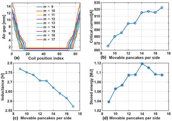
Figure 7.
Performance enhancement of single solenoid via gap op: (a) Air-gap distribution; (b): Critical current versus number of movable pancakes per side; (c): Inductance versus number of movable pancakes per side; (d): Stored energy versus number of movable pancakes per side.

Table 2.
Critical current, inductance, and energy storage capacity for movable pancakes per side ranging from 9 to 17.
Compared to typical superconducting modeling methods [34,35,36], the proposed intelligent optimization scheme substantially reduces computational time while preserving physical model accuracy. It achieves concurrent enhancements of 41.8% in energy storage capacity and 22.6% in critical current, delivering an efficient paradigm for large-scale HTS magnet design.
5. Optimization of the Multi-Solenoid Parallel Configuration
5.1. Multi-Solenoid Modeling
Based on the optimization results from the previous two steps, the design was extended to the optimization of a multi-solenoid parallel configuration. To meet the high-power compensation requirements in large-capacity microgrid systems, the superconducting magnet requires a very high critical current [37,38]. This paper employs solenoid magnets to design a 20 MJ-class SMES magnet. Since a single solenoid magnet cannot meet the 10 kA-class operating current requirement, a parallel configuration was introduced, consisting of 20 parallel-connected MJ-class superconducting solenoid coil units.
Figure 5 shows the parallel matrix diagram of multiple solenoids. The overall structure consists of a 4 × 5 solenoid matrix array. The inner and outer radii of each solenoid unit are r1 and r2, respectively. The gap between adjacent solenoid units in the horizontal and vertical directions are g1 and g2, respectively. The gap between adjacent solenoid units in the x-direction and y-direction are set as g1 and g2, respectively. The overall width K1 of the magnet is 8r2 + 3g2, and the length K2 is 10r2 + 4g1. For the 2.67 H/915 A/1.12 MJ superconducting solenoid coil, r1 and r2 are 0.48 m and 0.49 m, respectively.
For high-power compensation applications in microgrids, the 4 × 5 solenoid matrix array (20 units) needs to maintain an ultra-high critical current of 18 kA. However, the inherent electromagnetic anisotropy couples with the mutual inductance effects between adjacent coil units [39,40]. Insufficient coil spacing leads to superimposed mutual magnetic fields significantly enhancing the local field, resulting in degradation of the critical current [41,42]. To meet the stringent targets of 20 MJ stored energy and 0.13 H total inductance, coordinated optimization of the gap parameters is required to achieve the dual objectives of inductance and critical current. Given that meter-scale inter-unit gaps dominate the solenoid matrix array’s geometry, electromagnetic coil interaction forces are negligible within the electromagnetic optimization framework of this study.
All 20 coil units are solenoids with parallel central axes. The mutual inductance among any two solenoids is calculated as follows [43]:
Ω is the number of turns per solenoid; D is the average diameter of the solenoid; h is the height of the solenoid; z is the distance between the axes of the two solenoids; the structural parameters c = (z2 + h2)1/2, ξ = D/(2h), η = z/c.
Starting from the first-row solenoid, the units are sequentially defined from left to right as coil unit 1, 2, …, 20. The total inductance Li of the ith coil unit is calculated as:
L0 is the self-inductance of the ith coil unit; Mij is the mutual inductance among the ith coil unit and the remaining 19 coil units. It should be noted that since the structural parameters of all the 20 coil units are identical, the self-inductance of each unit is L0.
The total inductance Ltotal of the entire magnet is then calculated as:
5.2. Optimized Results
The co-optimization results of the multi-solenoid array are presented in Figure 8. Figure 8a quantifies the nonlinear dependence of the total inductance, Ltotal, on the inter-unit gap in the x-direction, g1, and the inter-unit gap in the y-direction, g2. The inductance exceeds the target value of 0.13 H for g1 < 2.5 and g2 < 4.5 m due to the strong magnetic coupling. Conversely, it decays below the target value when g1 > 3.0 m or g2 > 5.0 m, indicating very weak mutual inductance. The yellow grid surface in Figure 8a corresponds to the actual inductance value of 0.15 H at the global optimum. The overall dimensions of the optimized 20-unit array are approximately K1 = 18.2 m in width, and K2 = 24.0 m in length, with a height of 0.74 m per solenoid.

Figure 8.
Dependence of the multi-solenoid array performance on the inter-unit gaps: (a) total inductance; (b) stored energy.
Figure 8b presents the relationships among the energy storage capacity and the two gaps. The peak energy storage of 20 MJ is achieved at the optimal gap configuration of (g1, g2) = (2.44, 4.77) m. At this point, the total inductance is 0.15 H, and the critical current per unit is 827 A, representing a slight degradation of approximately 9.7% from the initial single-unit value. The blue grid surface marks ±10% tolerance range around the target inductance (0.13 H), i.e., 0.12 H ≤ Ltotal ≤ 0.14 H. Analysis of the data points within this range (scatter region) confirms an approximately linear relationship between the inductance deviation (ΔL) and the critical current degradation ratio (ΔIc/Ic0).
6. Conclusions
This study proposed a systematical methodology to overcome challenges in the design of large-scale SMES magnets. An analytical magnetic field computation framework integrating REBCO’s critical current anisotropy was established, addressing the limitation of conventional methods which neglect magnetic field vector coupling effects. An inductance calculation scheme incorporating exponentially decaying coupling coefficients was developed, substantially enhancing computational efficiency in multi-pancake systems.
To address high-dimensional nonlinear constrained problems, a dual-module genetic algorithm (discrete gap index + random increment encoding) was designed. Combined with an adaptive mutation strategy and parallel computation, it enhanced the optimization efficiency for MJ-class magnets by two orders of magnitude. In gap distribution optimization, by decoupling the variable space and employing a hierarchical iteration strategy, an increase of 22.6% in critical current and 41.8% in energy storage capacity was achieved.
The optimized single solenoid achieved an energy storage density of 1.12 MJ. The innovative coordinated gap design for the 20-unit (4 × 5) parallel array maintained the unit current at 915A under the constraint of a total inductance of 0.15 H, achieving an overall energy storage of 20 MJ. Multi-dimensional parameter analysis showed that with array gaps g1 = 2.44 m, g2 = 4.77 m, the critical current degradation caused by mutual inductance was effectively suppressed.
This study delivers a feasible engineering solution for high-capacity magnet design, while establishing a valuable framework and practical case study for academic research and educational applications in superconducting power technology.
Author Contributions
Conceptualization, H.Y., L.F. and X.C.; methodology, H.Y., L.F. and H.L.; software, H.Y., and H.L.; validation, L.F., M.T. and B.S.; writing—original draft preparation, H.Y., M.T.; writing—review and editing, L.F., X.C. and B.S.; supervision, X.C., L.F. and M.T.; project administration, X.C. All authors have read and agreed to the published version of the manuscript.
Funding
This work was supported by the Sichuan Science and Technology Program (2025ZNSFSC0447), Sichuan Provincial Higher Education Teaching Reform Project (JG2024-0690, JSJ2024012), and MOE (Ministry of Education in China) Thematic Case Project of China Academic Degrees and Graduate Education Development Center (ZT-2410636003).
Institutional Review Board Statement
Not applicable.
Informed Consent Statement
Not applicable.
Data Availability Statement
The original contributions presented in this study are included in the article. Further inquiries can be directed to the corresponding authors.
Conflicts of Interest
The authors declare no conflict of interest.
Appendix A. Full Expressions for Core Functions and
The complete definitions of the core functions and used in the 2D axisymmetric magnetic field model (Section 2.1) are provided here.
The function is given by:
The function is given by:
References
- Zhang, R.; Wang, L.; Hu, X.; Zhou, W.; Yang, S.; Li, Z.; Cheng, Z.; Su, C. Protection and Power Smoothing of a DFIG/DC Microgrid Hybrid Power System with SMES-Based Unified Power Quality Conditioner. IEEE Trans. Appl. Supercond. 2024, 34, 5401005. [Google Scholar] [CrossRef]
- Dunn, B.; Kamath, H.; Tarascon, J.-M. Electrical Energy Storage for the Grid: A Battery of Choices. Science 2011, 334, 928–935. [Google Scholar] [CrossRef]
- Zhang, X.; Feng, G. MMC-Based PV Grid-Connected System with SMES-Battery Hybrid Energy Storage System. IEEE Trans. Appl. Supercond. 2024, 34, 5702004. [Google Scholar] [CrossRef]
- Zhao, J.; Li, F.; Zhang, Q. Impacts of Renewable Energy Resources on the Weather Vulnerability of Power Systems. Nat. Energy 2024, 9, 1407–1414. [Google Scholar] [CrossRef]
- Li, C.; Zhao, Y.-F.; Vera, A.; Lesser, O.; Yi, H.; Kumari, S. Proximity-Induced Superconductivity in Epitaxial Topological Insulator/Graphene/Gallium Heterostructures. Nat. Mater. 2023, 22, 570–575. [Google Scholar] [CrossRef] [PubMed]
- Chen, X.; Gou, H.; Chen, Y.; Jiang, S.; Zhang, M.; Pang, Z.; Shen, B. Superconducting fault current limiter (SFCL) for a power electronic circuit: Experiment and numerical modelling. Supercond. Sci. Technol. 2022, 35, 045010. [Google Scholar] [CrossRef]
- Rogacki, K.; Los, A.; Dabrowski, B. Raising Critical Currents in YBaCuO-Type High-Temperature Superconductors by Mo Substitution. Low Temp. Phys. 2023, 49, 364–374. [Google Scholar] [CrossRef]
- Fang, S.; Lv, Z.; Chao, G. Method to Improve the Optimized Calculation Speed of Superconducting Magnetic Coil. IEEE Trans. Appl. Supercond. 2021, 31, 4901705. [Google Scholar] [CrossRef]
- Chen, X.; Pang, Z.; Gou, H.; Xie, Q.; Zhao, R.; Shi, Z.; Shen, B. Intelligent design of large-size HTS magnets for SMES and high-field applications: Using a self-programmed GUI tool. Supercond. Sci. Technol. 2021, 34, 095008. [Google Scholar] [CrossRef]
- Conway, J.T. Trigonometric Integrals for the Magnetic Field of the Coil of Rectangular Cross Section. IEEE Trans. Magn. 2006, 42, 1538–1548. [Google Scholar] [CrossRef]
- Hajiri, G.; Berger, K.; Trillaud, F.; Lévêque, J. Electromagnetic-Thermal Finite Element Model Coupled to Reduced Electrical Circuit for Simulating Inductive HTS Coils in Overcurrent Regimes. Cryogenics 2025, 148, 104068. [Google Scholar] [CrossRef]
- Li, K.; Li, K.; Fu, Y.; Zou, L.; Yang, L.; Peng, W.; Wang, Y. AC Loss Optimization of High Temperature Superconducting Magnetic Energy Storage Considering Energy Management Strategies in a Hydrogen-Battery System. J. Energy Storage 2024, 101, 113728. [Google Scholar] [CrossRef]
- Xue, C.; Ren, H.-X.; Jia, P.; Wang, Q.-Y.; Liu, W.; Ou, X.-J.; Sun, L.-T.; Silhanek, A.V. Holistic Numerical Simulation of a Quenching Process on a Real-Size Multifilamentary Superconducting Coil. Nat. Commun. 2024, 15, 10454. [Google Scholar] [CrossRef]
- Kim, S.K.; Shousha, R.; Yang, S.M.; Hu, Q.; Hahn, S.H.; Jalalvand, A.; Park, J.-K.; Logan, N.C.; Nelson, A.O.; Na, Y.-S.; et al. Highest Fusion Performance without Harmful Edge Energy Bursts in Tokamak. Nat. Commun. 2024, 15, 3990. [Google Scholar] [CrossRef]
- ALICE Collaboration; Acharya, S.; Agarwal, A.; Aglieri Rinella, G.; Aglietta, L.; Agnello, M.; Agrawal, N.; Ahammed, Z.; Ahmad, S.; Ahn, S.U.; et al. Proton Emission in Ultraperipheral Pb-Pb Collisions at √sNN=5.02 TeV. Phys. Rev. C 2025, 111, 054906. [Google Scholar] [CrossRef]
- Liu, W.; Dai, S.; Ma, T.; Shi, Y.; Song, M. Electromagnetic Optimization of a Hybrid Toroidal Magnet for 10 MJ HTS SMES System. Phys. C Supercond. Its Appl. 2024, 626, 1354589. [Google Scholar] [CrossRef]
- Li, W.; Ding, Y.; Yang, Y.; Sherratt, R.S.; Park, J.H.; Wang, J. Parameterized Algorithms of Fundamental NP-Hard Problems: A Survey. Hum.-Centric Comput. Inf. Sci. 2020, 10, 29. [Google Scholar] [CrossRef]
- Zhou, B.; Zhang, Z.; Liu, Q.; Zhang, X.; Strickland, N.; Suo, H.; Wang, L.; Liu, J.; Wang, Q. Anisotropic In-Plane Field Angle Dependence of Critical Current in Commercial REBCO Tapes and Its Impact on Toroidal Field Magnet for Compact Tokamak Fusion Device. Supercond. Sci. Technol. 2025, 38, 015016. [Google Scholar] [CrossRef]
- Wang, D.; Ding, Y.; Mao, H.-K. Future Study of Dense Superconducting Hydrides at High Pressure. Materials 2021, 14, 7563. [Google Scholar] [CrossRef]
- Zhang, X.; Hou, J.; Xia, W.; Xu, Z.; Yang, P.; Wang, A. Destabilization of the Charge Density Wave and the Absence of Superconductivity in ScV6Sn6 under High Pressures up to 11 GPa. Materials 2022, 15, 7372. [Google Scholar] [CrossRef]
- Strickland, N.M.; Wimbush, S.C.; Soman, A.A.; Long, N.J.; Rupich, M.W.; Knibbe, R.; Li, M.; Notthoff, C.; Kluth, P. Near-Isotropic Enhancement of the 20 K Critical Current of REBa2Cu3O7 Coated Conductors from Columnar Defects. Supercond. Sci. Technol. 2023, 36, 055001. [Google Scholar] [CrossRef]
- Boran, Y.; Kara, H.; Inanir, F.; Yildiz, S. Conceptual Design and Sensitivity Analysis of MRI Magnets from REBCO HTS Tapes. IEEE Trans. Appl. Supercond. 2022, 32, 4605908. [Google Scholar] [CrossRef]
- Shi, S.; Liang, R. Numerical Analysis of REBCO High-Temperature Superconducting (HTS) Coils Based on Screening Effect. J. Supercond. Nov. Magn. 2022, 35, 3487–3496. [Google Scholar] [CrossRef]
- Zhang, H.; Suo, H.; Wang, L.; Ma, L.; Liu, J.; Zhang, Z.; Wang, Q. Database of the Effect of Stabilizer on the Resistivity and Thermal Conductivity of 20 Different Commercial REBCO Tapes. Supercond. Sci. Technol. 2022, 35, 045016. [Google Scholar] [CrossRef]
- Taheri, B.; Pinto, V.; Cemmi, A.; Di Sarcina, I.; Scifo, J.; Masi, A.; Verna, A.; Celentano, G. Sensitivity of REBCO Tapes and Thin Film to γ-Irradiation. IEEE Trans. Appl. Supercond. 2024, 34, 6600105. [Google Scholar] [CrossRef]
- Pi, W.; Li, B.; Zhao, Y.; Li, Z.; Guo, L.; Wang, Y.; Shi, Q. Self-Shielding HTS DC Cable Made by REBCO Tapes with Different Widths. IEEE Trans. Appl. Supercond. 2024, 34, 4802306. [Google Scholar] [CrossRef]
- Cai, C.-B.; Guo, Y.-Q.; Zhao, Y. The New Power Transmission Material—REBaCuO High-Temperature Superconducting Coated Conductor. Physics 2020, 49, 747–754. [Google Scholar] [CrossRef]
- Qian, L.; Chen, M.; Cui, K.; Shi, G.; Wang, J.; Xia, Y. Modeling of Mutual Inductance Between Two Misalignment Planar Coils in Wireless Power Transfer. IEEE Microw. Wirel. Compon. Lett. 2020, 30, 814–817. [Google Scholar] [CrossRef]
- Kwak, S.; Park, M.; Kim, W.; Hahn, S.; Lee, S.; Lee, J.; Choi, K.; Han, J.; Bae, J.; Kim, S. The Optimal Design of 600 kJ SMES Magnet Based on Stress and Magnetic Field Analysis. IEEE Trans. Appl. Supercond. 2008, 18, 713–716. [Google Scholar] [CrossRef]
- Robert, B.C.; Fareed, M.U.; Ruiz, H.S. How to Choose the Superconducting Material Law for the Modelling of 2G-HTS Coils. Materials 2019, 12, 2679. [Google Scholar] [CrossRef]
- Xu, Y.; Zhang, M.; Wang, D.; Yang, M.; Liang, C. Hybrid Gaussian Quantum Particle Swarm Optimization and Adaptive Genetic Algorithm for Flexible Job-Shop Scheduling Problem. Eng. Appl. Artif. Intell. 2025, 154, 110882. [Google Scholar] [CrossRef]
- Tang, P.-H.; Tseng, M.-H. Adaptive Directed Mutation for Real-Coded Genetic Algorithms. Appl. Soft Comput. 2013, 13, 600–614. [Google Scholar] [CrossRef]
- Yan, L.; Deng, H. Adaptive Genetic Algorithm for Computer Course Scheduling System under the Background of Educational Informatization. Syst. Soft Comput. 2025, 7, 200324. [Google Scholar] [CrossRef]
- Garkki, B.; Revathi, S. Double-Pancake Superconducting Coil Integrated with DFIG-Based Wind Power Systems under Voltage-Dip Events: Design and Performance Analysis Study. Phys. C Supercond. Its Appl. 2024, 626, 1354601. [Google Scholar] [CrossRef]
- Hong, Y.; Zheng, J.; Liao, H. Modeling of High-Tc Superconducting Bulk Using Different Jc–T Relationships over Dynamic Permanent Magnet Guideway. Materials 2019, 12, 2915. [Google Scholar] [CrossRef]
- Chen, Y.; Chen, X.; Fu, L.; Jiang, S.; Shen, B. Superconducting Hydrogen-Electricity Multi-Energy System for Transportation Hubs: Modeling, Technical Study and Economic-Environmental Assessment. Appl. Energy 2025, 126823. [Google Scholar]
- Gabriel, L.M.N.; Adebisi, J.A.; Ndjuluwa, L.N.P.; Chembe, D.K. Investigation of Smart Grid Technologies Deployment for Energy Reliability Enhancement in Electricity Distribution Networks. Frankl. Open 2025, 10, 100227. [Google Scholar] [CrossRef]
- Bai, J.; Wu, X.; Chen, X.; Zhang, Z.; Fu, L.; Zhao, C.; Qing, K.; Luo, Q.; Gong, S.; Shen, B. Combined space cooling/heating and domestic hot water supply driven by data center waste heat: Complementary energy conservation, economic capacity optimization and generic analysis framework. Build. Environ. 2025, 283, 113402. [Google Scholar] [CrossRef]
- Li, C.; Li, G.; Xin, Y.; Li, B. Electromagnetic Interaction between the Closed Superconducting Coil and the Moving Permanent Magnet: The State of the Art. Supercond. Sci. Technol. 2025, 38, 013001. [Google Scholar] [CrossRef]
- Liang, S.; Ren, L.; Ma, T.; Xu, Y.; Tang, Y.; Tan, X. Study on Quenching Characteristics and Resistance Equivalent Estimation Method of Second-Generation High Temperature Superconducting Tape under Different Overcurrent. Materials 2019, 12, 2374. [Google Scholar] [CrossRef]
- Ma, D.X.; Matsumoto, S.; Teranishi, R.; Ohmura, T.; Kiyoshi, T.; Otsuka, A.; Hamada, M.; Maeda, H.; Yanagisawa, Y.; Nakagome, H. Degradation Analysis of REBCO Coils. Supercond. Sci. Technol. 2014, 27, 085014. [Google Scholar] [CrossRef]
- Trillaud, F.; dos Santos, G.; Gonçalves Sotelo, G. Essential Material Knowledge and Recent Model Developments for REBCO-Coated Conductors in Electric Power Systems. Materials 2021, 14, 1892. [Google Scholar] [CrossRef] [PubMed]
- Shi, Z.H.; Chen, X.Y.; Qiu, Z.C. Modeling of Mutual Inductance Between Superconducting Pancake Coils Used in Wireless Power Transfer (WPT) Systems. IEEE Trans. Appl. Supercond. 2019, 29, 5500904. [Google Scholar] [CrossRef]
Disclaimer/Publisher’s Note: The statements, opinions and data contained in all publications are solely those of the individual author(s) and contributor(s) and not of MDPI and/or the editor(s). MDPI and/or the editor(s) disclaim responsibility for any injury to people or property resulting from any ideas, methods, instructions or products referred to in the content. |
© 2025 by the authors. Licensee MDPI, Basel, Switzerland. This article is an open access article distributed under the terms and conditions of the Creative Commons Attribution (CC BY) license (https://creativecommons.org/licenses/by/4.0/).