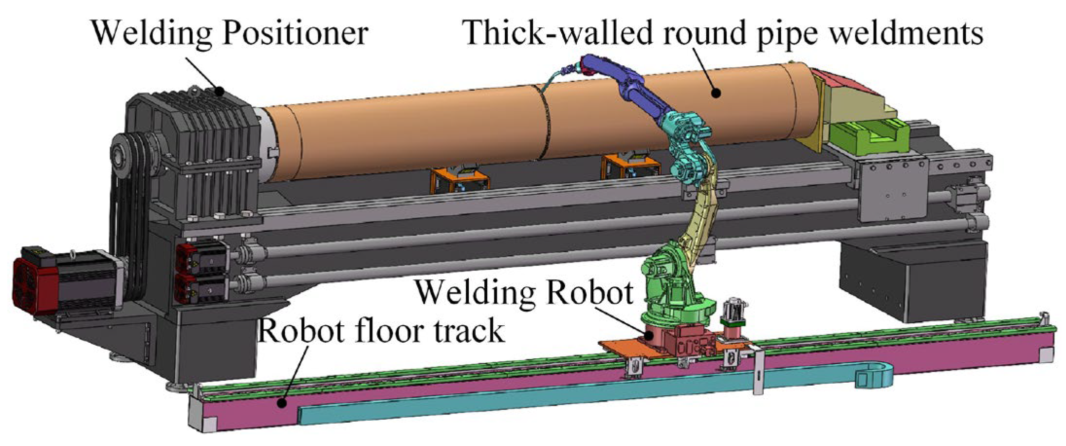
To determine the optimal welding sequence for thick-walled circular pipes, welding simulations were conducted using ANSYS Workbench. First, a simplified model of the thick-walled circular pipe and the corresponding weld geometry was created in SolidWorks (2020). Then, based on the equal-height and equal-area method, the values of ri and dj were calculated, and the moving heat source trajectory equations for each weld pass were established. Subsequently, the weld model was imported into ANSYS Workbench, where nonlinear material properties were defined. The transient thermal field was first computed and then imported into the transient structural module to calculate residual stress and deformation. Finally, the simulation results were compared to determine the optimal welding sequence.
4.1. Pre-Simulation Processing
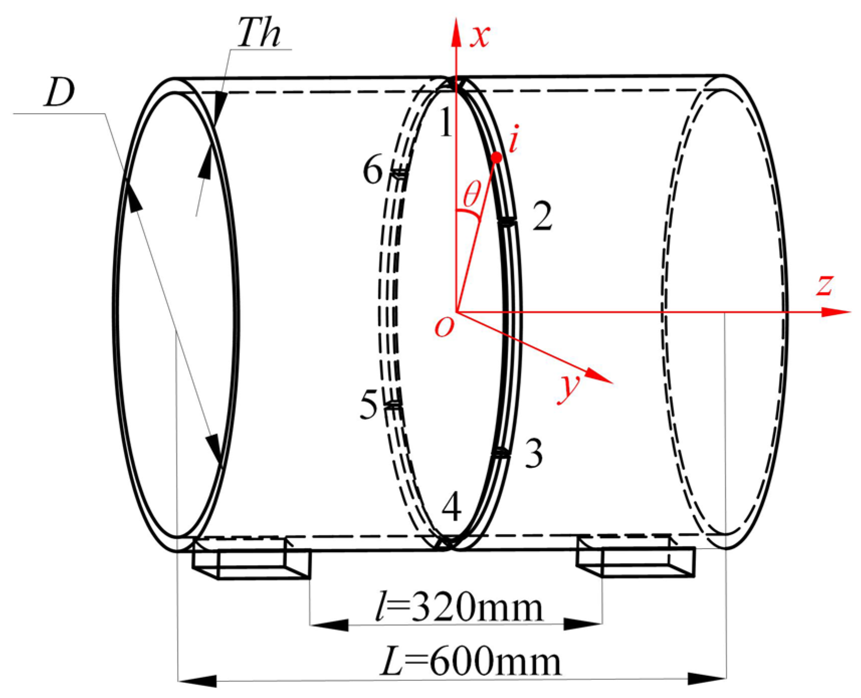
To enhance the generality of the study on segmented multi-layer multi-pass welding of thick-walled circular pipes, three pipe specimens with wall thicknesses
Th of 10 mm, 15 mm, and 20 mm were selected for welding simulation. The remaining parameters of the welding model are listed in
Table 1.
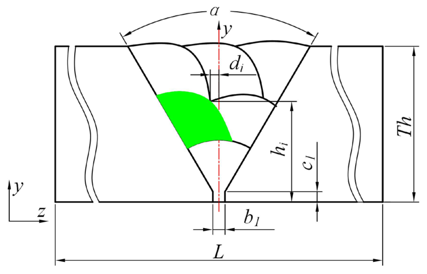
In practical welding applications, circular pipes with a diameter greater than 8 mm typically require three or more weld layers. Since the 10 mm wall thickness is relatively thin, the welding voltage and current used for 10 mm thick pipes are lower than those for 15 mm and 20 mm pipes when the welding speed remains constant. As a result, the weld cross-section is smaller. The weld geometries for the three wall thicknesses are shown in
Figure 6.
For 10 mm and 15 mm thick pipes, the weld consists of three layers with six passes, while for the 20 mm thick pipe, the weld consists of four layers with ten passes.
Prior to performing automated robotic welding on the circular pipe, six tack welds were manually applied to secure the workpiece. As a result, the circular weld seam was divided into six segments, as illustrated in
Figure 7. In the figure, numerals 1 to 6 represent the six tack welds, while letters a to f denote the six corresponding welding segments.
During the welding process, abrupt thermal expansion and contraction of the workpiece induce stress and strain, which in turn lead to welding deformation and residual stress. To reduce welding deformation in thick-walled circular pipes, four welding sequence strategies, as illustrated in
Figure 8, are proposed in this study. The numbers 1–6 in the diagram indicate the sequential order of welding.
N1: Sequential Circulation Method—welds are completed sequentially in a single rotational direction.
N2: Symmetric Continuous Method—the weld seam is divided into two large sections (left and right); three segments are welded continuously in one direction, then the remaining three are welded in the reverse direction, starting from the initial point.
N3: Jump-Symmetric Method—welding is performed in a continuous, symmetric, and alternating pattern following a predefined direction.
N4: Cross-Symmetric Method—the weld seam is divided into four parts; two larger sections (top and bottom) are welded first in a crosswise manner, followed by the remaining two smaller sections (left and right).
After constructing the welding model, it was imported into ANSYS Workbench, and material properties were assigned. As marine thick-walled circular pipes are often used in oceanic and harsh climatic environments, they must possess high impact resistance and fatigue strength to withstand wave-induced loads, as well as long-term durability under low temperatures and cold climates. Therefore, the material must also be capable of resisting high humidity and salt spray corrosion.
Based on shipbuilding industry standards [
20] and practical applications in shipyards, this study selected Q460 high-strength structural steel, which meets the complex requirements of both nearshore and ocean-going vessels, as well as offshore engineering structures. According to the standards for seamless carbon steel pipes used in shipbuilding, the chemical composition of Q460 steel is listed in
Table 2.
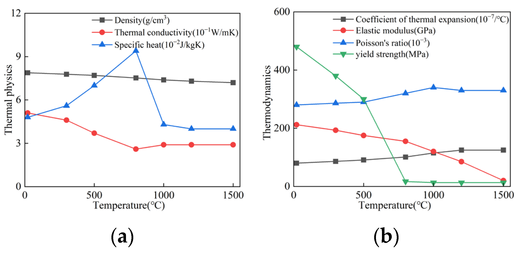
During the welding process, the temperature of the workpiece material rises instantaneously under the action of the heat source, causing it to melt and form a molten pool, which is then filled with filler wire to create the weld seam. In this process, the material properties of the workpiece undergo nonlinear changes.
The calculation of the welding temperature field depends on the thermal-physical properties of the steel, while welding deformation and residual stress are influenced by its thermo-mechanical properties. Based on the relevant literature [
21], the nonlinear thermal-physical and thermo-mechanical properties of Q460 high-strength structural steel were obtained and are shown in
Figure 9.
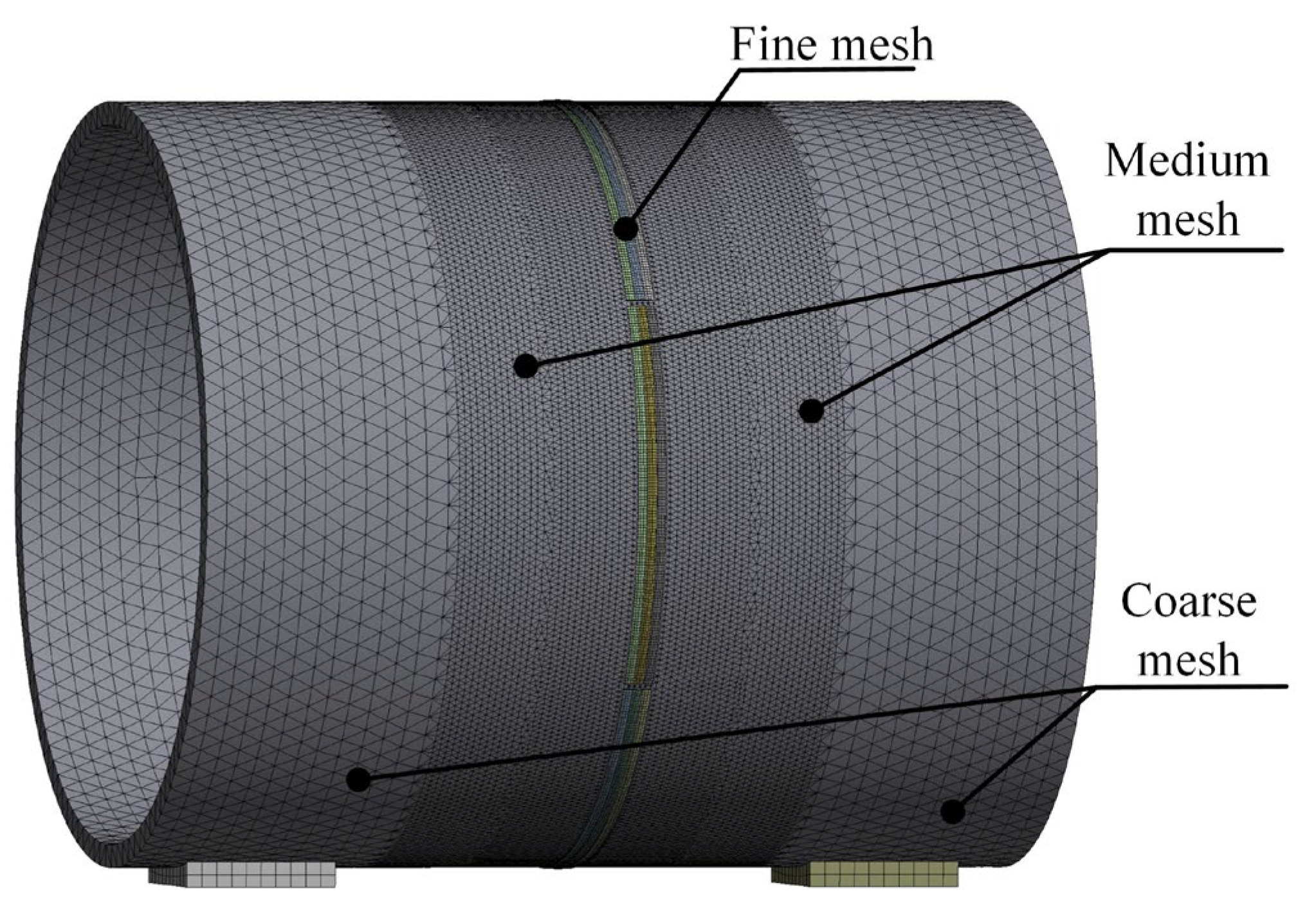
After assigning the material properties to the circular pipe in the ANSYS (2024R1) Workbench, mesh generation must be performed. The mesh size directly affects the computational accuracy. An excessively fine mesh can waste computational resources and reduce simulation efficiency.
Therefore, in this study, a multi-scale meshing strategy was adopted: a coarse mesh was applied to regions far from the weld seam, a moderately fine mesh was used near the weld seam, and a fine mesh was applied to the weld seam and its surrounding area. The weld seam was meshed using multi-region hexahedral elements of type SOLID186, while the remaining parts of the thick-walled circular pipe were automatically meshed using SOLID187 elements, as shown in
Figure 10.
4.2. Simulation Method
After completing the pre-processing setup, numerical simulation of the thick-walled circular pipe welding was performed. The first step is to calculate the temperature field during the welding process of the thick-walled circular pipe. In finite element theory, the transient heat conduction matrix for the thick-walled circular pipe is given by:
where [
K] is the total heat conduction matrix of the thick-walled circular pipe element, [
Q] is the total heat load matrix representing the heat source, [
C] is the specific heat capacity matrix, {
T} denotes the nodal temperature vector of the thick-walled circular pipe, and {
} represents the time derivative of the nodal temperature vector.
Due to the localized rapid temperature rise and subsequent sudden cooling caused by the welding heat source on the pipe, and the nonlinear variation of material physical properties with temperature during the entire process, the above equation can be expressed as:
Under the heating of the heat source, the thick-walled circular pipe workpiece undergoes thermal expansion and contraction. However, due to constraints imposed on each micro-element of the pipe by various factors, free expansion or contraction is restricted, resulting in thermal stresses.
According to thermoelasticity theory, the total elastic strain
d{
ε}
all of the pipe material is assumed to be composed of the sum of the elastic strain increment
d{
ε}
el caused by external forces and the thermal strain increment
d{
ε}
hot caused by temperature changes. The elastic strain {
ε}
el is calculated based on elastic mechanics principles, while the thermal strain {
ε}
hot is computed according to thermoelasticity theory.
Considering that plastic deformation occurs in the vicinity of the weld pool during the welding process of the circular pipe workpiece [
22,
23], the strain equation representing the total strain increment {
ε}
all can be expressed as:
where,
d{
ε}
p represents the plastic strain increment, which is related to the yield function of the circular pipe material.
The relationship between the nodal displacement increment {
δ}
e of element
e in the circular pipe workpiece and the initial strain increment [
R]
e induced by temperature can be expressed as:
where [
K]
e is the element stiffness matrix, and [
B] is the coefficient matrix related to the element nodes.
During the welding of thick-walled circular pipes, complex welding conditions may lead to certain deviations. To minimize these discrepancies, a correction coefficient matrix [
G] is introduced in this study to adjust the stiffness matrix. The corrected element stiffness matrix is expressed as follows:
The nodal displacement increment {
δ}
e of the thick-walled circular pipe can be expressed as:
The total welding deformation
w of the circular pipe is given by:
Based on finite element theory, this study simulated the temperature fields of thick-walled circular pipes under different welding sequences using Ansys (2024R1) Workbench Mechanical’s Transient Thermal module (Software source: Ansys, Inc., Canonsburg, PA, USA).
The simulations were conducted on a computer equipped with an Intel (Intel Corporation, Santa Clara, CA, USA) i7-11700K processor, 96 GB of RAM, and a GP100 graphics card. The resulting temperature field data were then imported into the transient structural module to calculate the deformation and stress corresponding to each welding sequence.
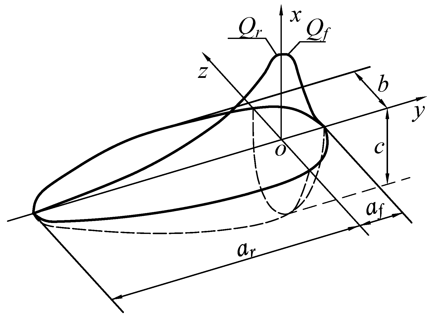
In actual welding processes, since thick-walled circular pipes are typically welded directly in shipyards where the environment is relatively enclosed, the convective heat transfer between the workpiece surface and air was set to 10 W/(m2·°C) when defining the boundary conditions of the temperature field. As the heat source in this study adopts a moving double-ellipsoidal model, the heat source was applied in the Workbench transient thermal module via APDL command streams. To reduce computation time, the simulation time step was set to 1 s, and the transient integration option was enabled. To better approximate the actual welding process, the element birth and death technique in ANSYS was employed.
In this sequential coupled thermal-mechanical analysis, the temperature field data from the thermal analysis based on SOLID70 elements is automatically mapped to the SOLID186/SOLID187 structural model using ANSYS’s LDREAD command. This process employs a shape function interpolation algorithm to automatically generate temperature values for the intermediate nodes of quadratic elements, enabling precise transfer of thermal-mechanical loads from linear elements to quadratic elements. This process automatically interpolates nodal temperatures from the linear thermal mesh onto the quadratic structural mesh, ensuring consistency of the coupled thermo-mechanical model. Sequential coupling of transient thermal analysis and transient structural thermomechanical analysis was performed without considering the effects of metallurgical phase transformations. The mechanical constitutive model adopted a bilinear isotropic hardening rule based on the von Mises yield criterion. Since welding simulation involves large deformation problems, the “Full Newton-Raphson” method was selected in the transient structural module, with Weak Spring and Large Deflection options enabled. To improve computational efficiency, automatic line search and the SPARSE solver were used. Fixed supports were applied at the bottom of the support blocks, and gravity G was applied in the negative x-direction.
In the welding sequence optimization simulations, the 10 mm thick pipe used a welding current of 190 A, a voltage of 23.6 V, and a welding speed of 10.5 mm/s. The 15 mm and 20 mm thick pipes used a welding current of 220 A, a voltage of 24.8 V, and a welding speed of 10.5 mm/s. According to the actual working conditions of the shipyard, the welding thermal efficiency is 0.7. The parameters of the double ellipsoidal heat source are shown in
Table 3.
For each wall thickness, different welding sequences were compared in terms of welding deformation and residual stress to determine the optimal welding sequence. Excluding the first manually applied TIG root pass, the 10 mm and 15 mm pipes required five additional weld passes, completing welding at 750 s. The 20 mm pipe required nine additional weld passes, with welding completed at 1350 s.
4.3. Results and Discussion
In welding simulation, strict requirements are imposed on the heat input. After applying the heat source, the heat source distribution is shown in
Figure 11. It can be observed from the figure that the heat source is successfully applied to the circular pipe weld seam and moves rotationally along the weld seam, ensuring the accuracy of the heat source application and thus guaranteeing the correctness of the welding simulation.
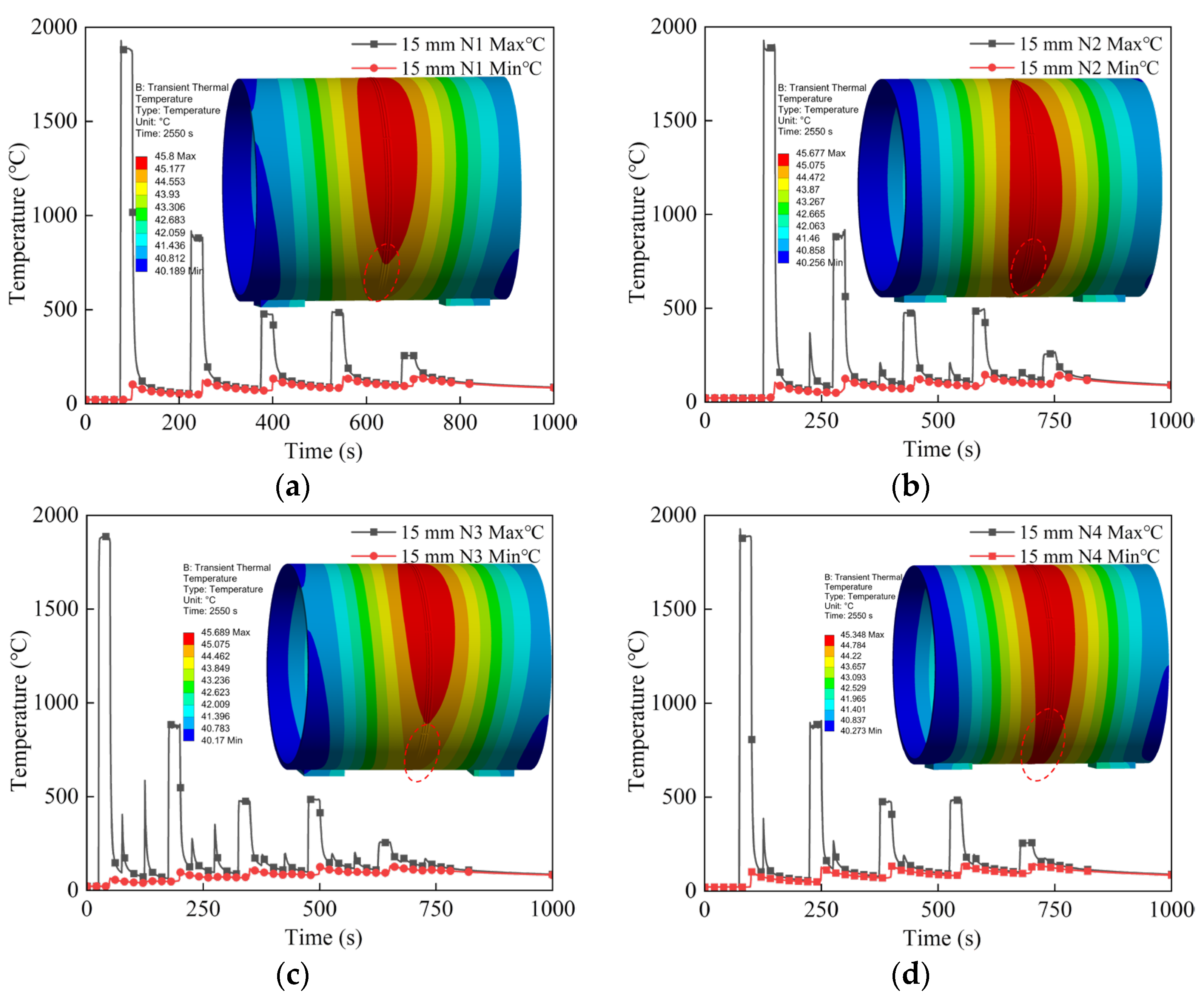
Taking the 15 mm wall thickness circular pipe as an example, after the heat source is applied, the temperature variation of segment
d in the first weld pass was monitored under four different welding sequences during robotic welding. As shown in
Figure 12, the temperature of segment
d rapidly rises above the steel melting point during welding and sharply drops after welding completion.
With the addition of subsequent weld passes, previously deposited weld beads are reheated by the existing molten pool, causing temperature increases. Moreover, the higher the number of weld layers, the less influence the current molten pool has on the underlying welds [
24]. Slight differences in the temperature variations of segment
d under different welding sequences result in localized uneven heating and cooling, which in turn easily cause welding deformation and residual stress.
Fifteen minutes after welding completion, the overall temperature of the pipe for all four welding sequences stabilized around the mid-40s °C, with the maximum temperature dropping to approximately 45 °C. This is very close to actual welding conditions in shipyards, thereby validating the accuracy of the welding temperature field simulated in this study.
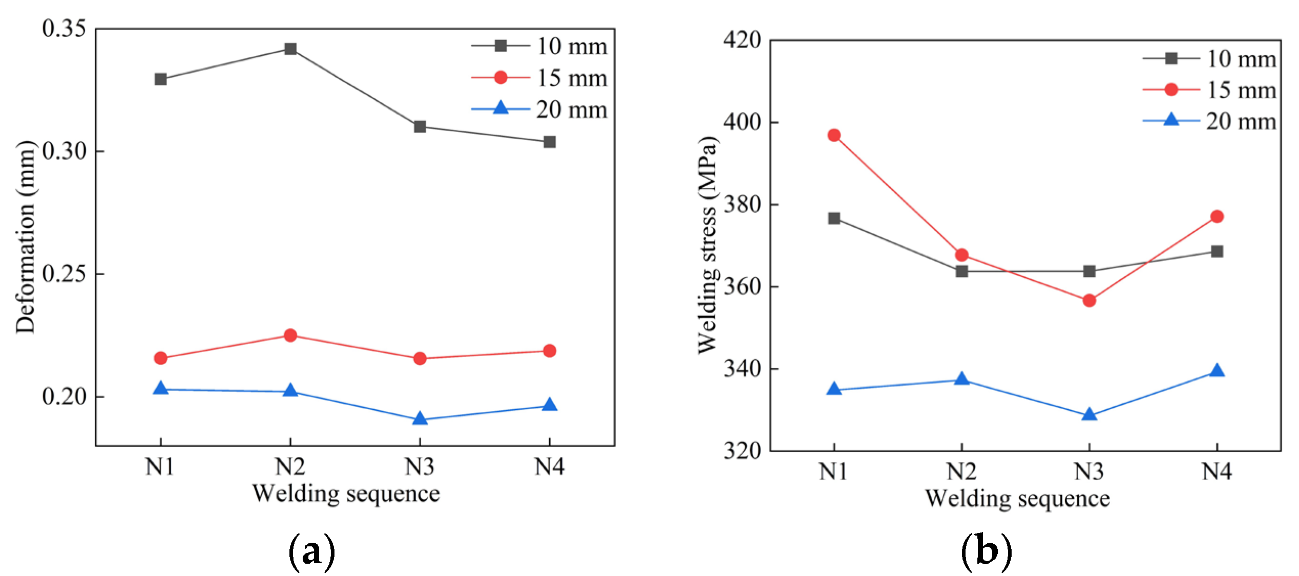
After calculating the temperature field in the transient thermal analysis, the data were imported into the transient structural module, and APDL scripts were written to compute welding deformation and residual stress for pipes with three different wall thicknesses under various welding sequences. The simulation results are shown in
Figure 13. For the 10 mm thick pipe, the welding deformation under the N3 sequence was 0.3101 mm, and the post-weld residual stress was 363.78 MPa. Compared to the maximum welding deformation of 0.34172 mm caused by N2, this represents a reduction of 9.25%, and compared to the maximum welding residual stress of 376.67 MPa caused by N1, a reduction of 3.42%.
For the 15 mm thick pipe, the welding deformation under N3 was 0.21562 mm, and the residual stress was 356.67 MPa. Compared to the maximum welding deformation of 0.22507 mm caused by N2, the deformation decreased by 4.19%, and the residual stress decreased by 10.13% relative to the maximum residual stress of 396.88 MPa caused by N1.
For the 20 mm thick pipe, the welding deformation under N3 was 0.19069 mm, and the residual stress was 328.62 MPa. Compared to the maximum welding deformation of 0.20303 mm caused by N1, the deformation decreased by 6.07%, and the residual stress decreased by 2.57% relative to the maximum residual stress of 337.31 MPa caused by N4.
In summary, the average welding deformation of the three pipe thicknesses under the N3 welding sequence decreased by 6.50%, and the residual stress decreased by 5.37%, indicating that the N3 welding sequence is the optimal choice.
To further validate that the N3 jump-symmetric welding sequence is optimal, axial monitoring points were selected at the locations of maximum deformation and maximum stress in the circular pipe welding simulations. In
Figure 14, 15 monitoring points were selected along the horizontal axis, as indicated by the numbers 1–15 in the figure. The results are shown in
Figure 14a–c. From the axial deformation data, it can be seen that the welding deformation of thick-walled circular pipes is primarily concentrated near the weld seam and diffuses outward, extending all the way to the pipe ends, causing an upward warping tendency at the pipe mouths. Although the welding parameters for the 15 mm and 20 mm thick pipes are the same, the 20 mm thick pipe exhibits larger deformation at the edges and more pronounced warping. Under identical welding processes, greater wall thickness leads to more significant thermal expansion effects. Thicker pipes require absorbing more heat due to their larger volume during welding, resulting in greater temperature gradients and larger volumetric expansion.
Figure 14d–f shows that the maximum residual stresses occur near the weld spots aligned with the support blocks. The presence of support blocks induces tensile stress at the bottom during welding. In contrast, thinner pipes dissipate heat more quickly, leading to smaller temperature differences and reduced thermal expansion effects.
The welding simulation results indicate that the greatest deformation occurs near the weld spots, while the welding residual stress mainly concentrates around the weld seams. The maximum residual stress occurs near the weld spots at the support block locations [
25]. Therefore, before robotic welding, these weld spots require additional reinforcement and thickening during tack welding to prevent weld spot failure caused by excessive deformation or stress during welding. A comprehensive comparison of axial deformation and stress in pipes of three wall thicknesses under different welding sequences shows that the N3 jump-symmetric welding sequence effectively suppresses both welding deformation and residual stress.
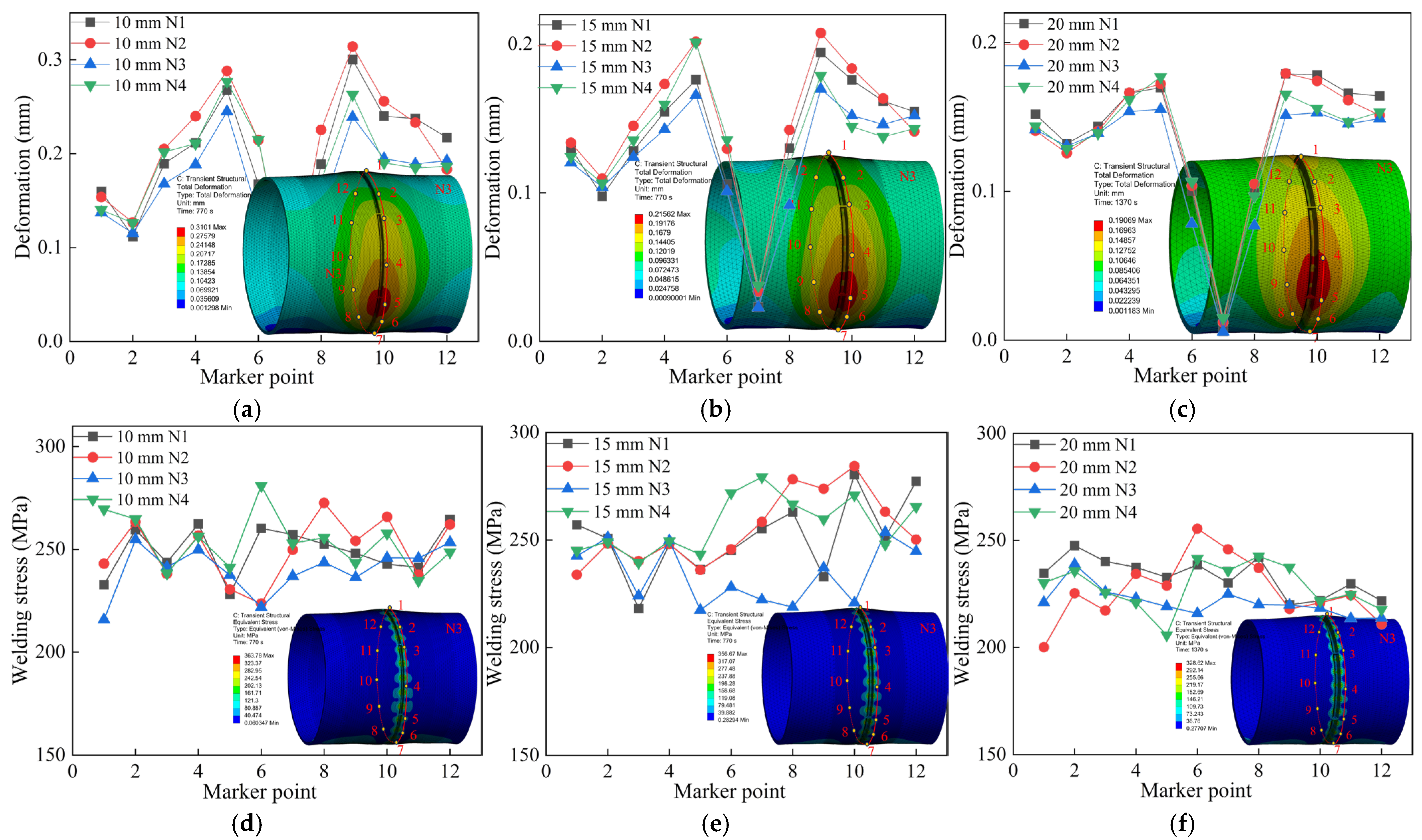
Furthermore, deformation of the circular pipe was monitored at a distance of 15 mm from the weld seam, and post-weld residual stress was monitored at 5 mm from the weld seam, as shown in
Figure 15. Twelve inspection points are uniformly distributed radially along the thick-walled circular pipe, as indicated by numbers 1-12 in the figure. These two regions belong to the welding heat-affected zone (HAZ) [
26]. By comparing the radial deformation and stress, it can be seen that the welding performance of the three wall-thickness pipes is optimal under the N3 jump-symmetric welding sequence.
The pipe deformation is minimal at the support blocks and larger on both sides of the bottom, while the residual stress around the weld seam is relatively high. Due to the cyclic reheating caused by multi-layer multi-pass welding in the heat-affected zone, the base metal near this area undergoes thermal expansion and contraction. The closer to the weld zone, the more likely plastic deformation occurs and stress increases [
27]. Therefore, welding thick-walled pipes requires not only selecting the optimal welding sequence but also strictly controlling welding parameters during the process. Post-weld annealing treatment and manual correction of deformation areas are also necessary to ensure structural integrity.
To validate the physical behavior predicted by the model, the simulation results for the circular pipe were compared with the existing literature on pipe welding simulations [
16,
21]. The trends in temperature and stress field distributions align with those reported in the existing literature. This confirms the validity of the present simulation results.
A comprehensive comparison of welding simulations for 10 mm, 15 mm, and 20 mm thick circular pipes under four different welding sequences shows that the N3 jump-symmetric welding sequence yields the best welding performance for thick-walled circular pipes. This welding sequence effectively suppresses welding deformation, reduces post-weld residual stress, and improves overall welding quality.
