
Clinch-Bonding Process for Ultra-High-Strength Steel and A5052 Aluminum Alloy Sheets


Highlights
- The effects of sheet combinations on the joined cross-sectional shapes in the clinch-bonding process for 780 MPa steel and A5052 aluminum alloy sheets were investigated.
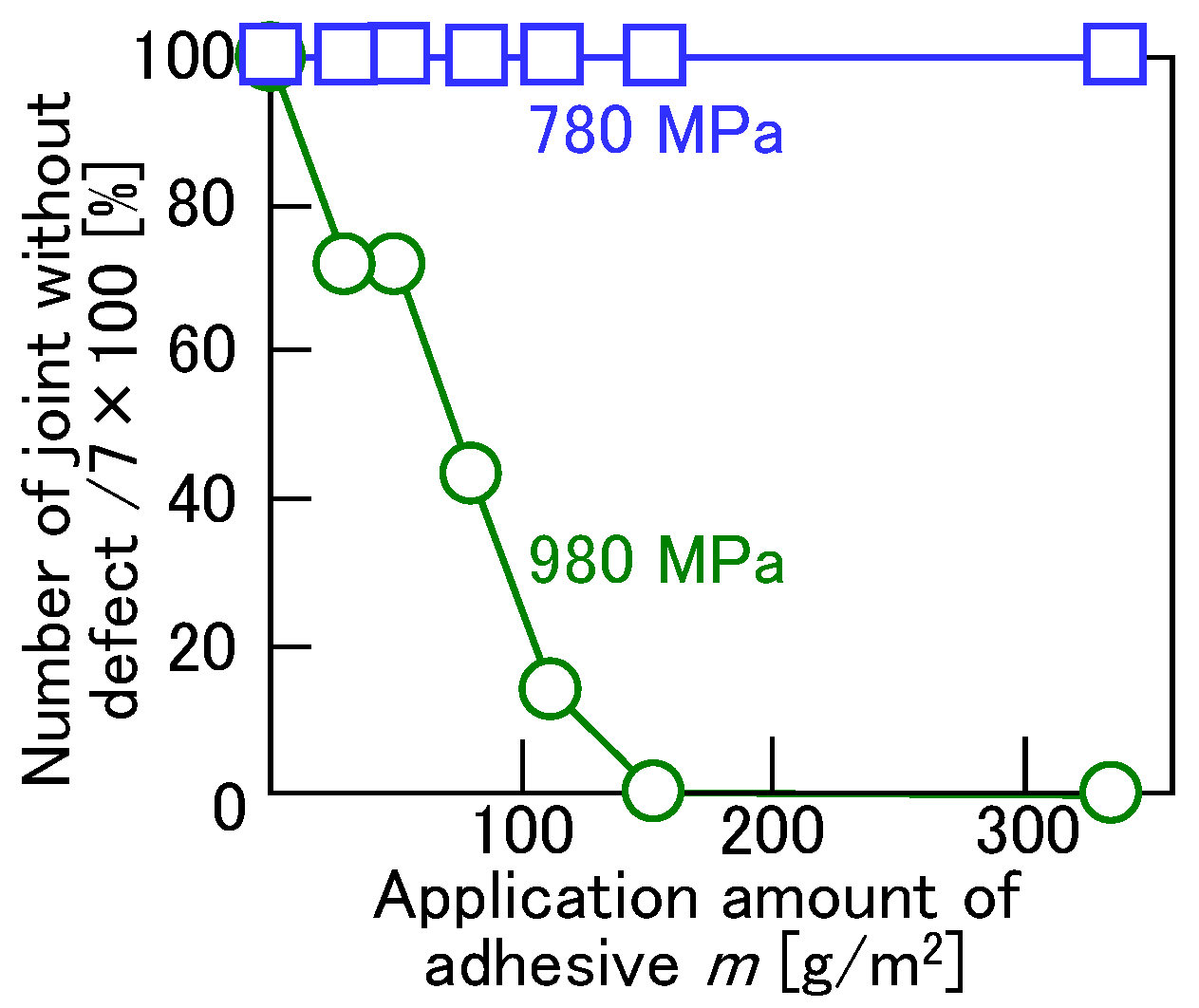
- In joining 980 MPa steel and aluminum alloy sheets, the effects of joining conditions on joinability were examined in detail.
- To improve the joining of 980 MPa steel and aluminum alloy sheets, controlling material flow using adhesive with fine particles in the clinch-bonding process was introduced.
Abstract

1. Introduction
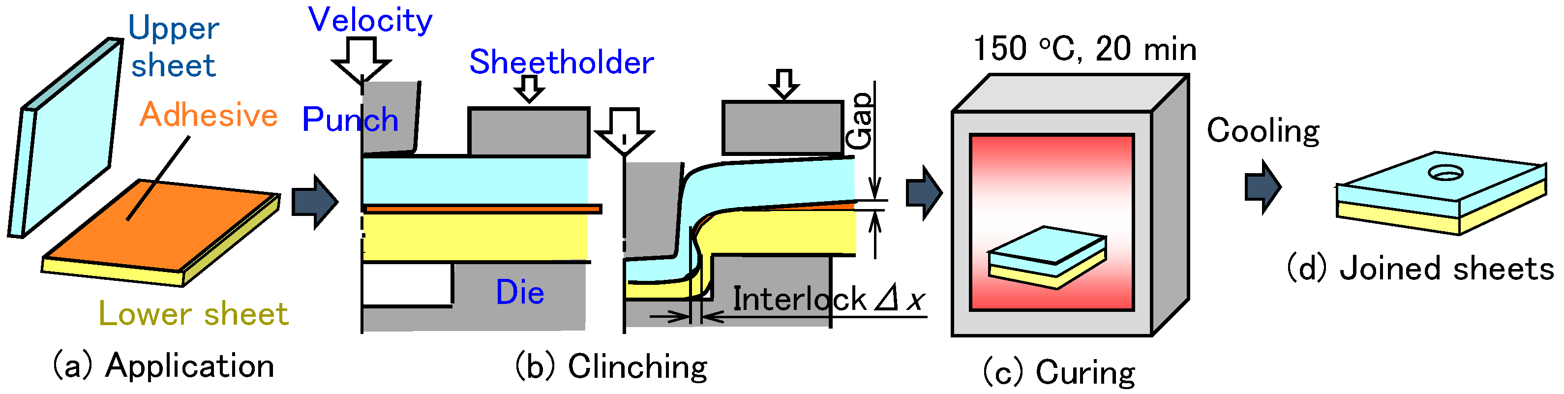
2. Clinch-Bonding Process for 780 MPa High-Strength Steel and Aluminum Alloy Sheets
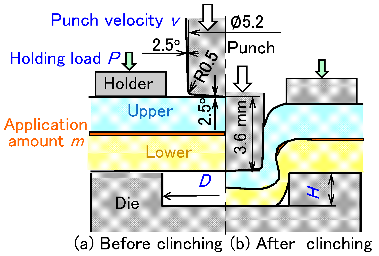
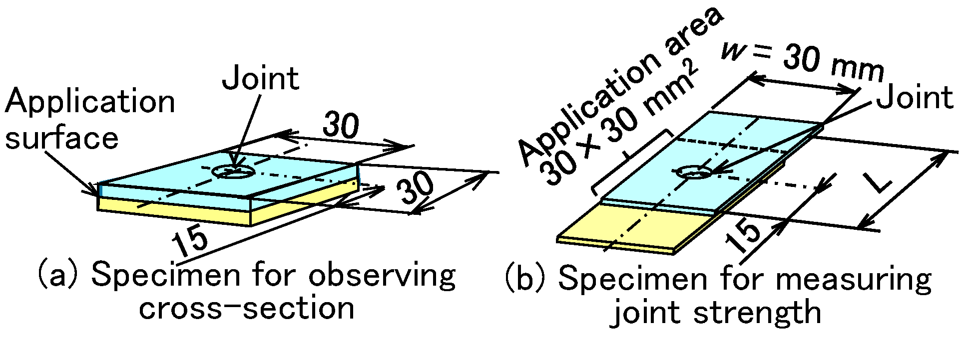
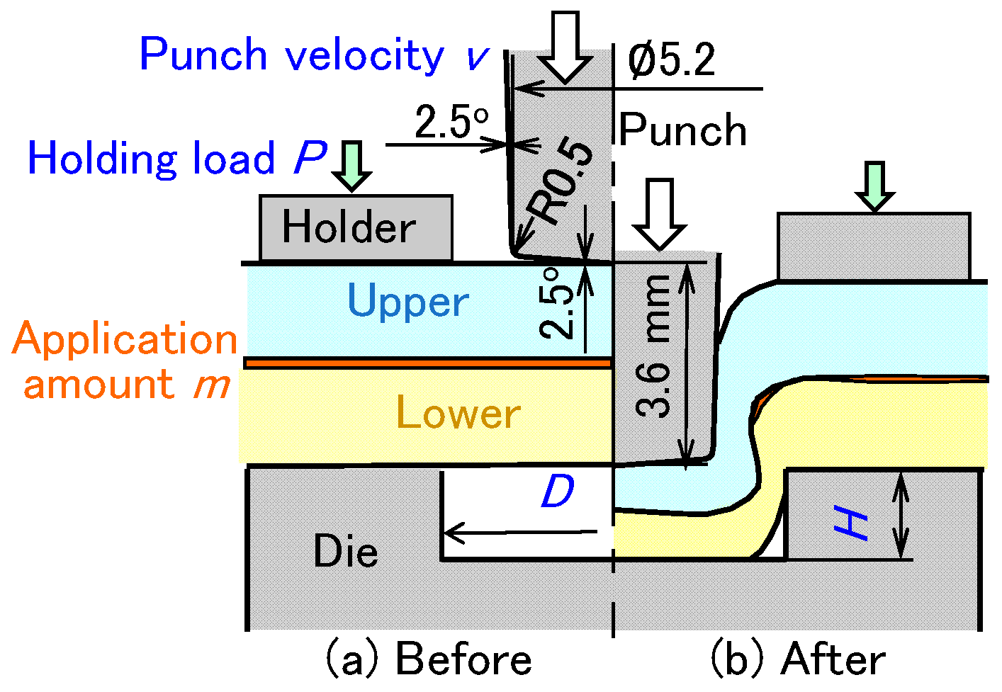
2.1. Sheet Materials, Clinching Methods, and Tension-Shear Test Conditions
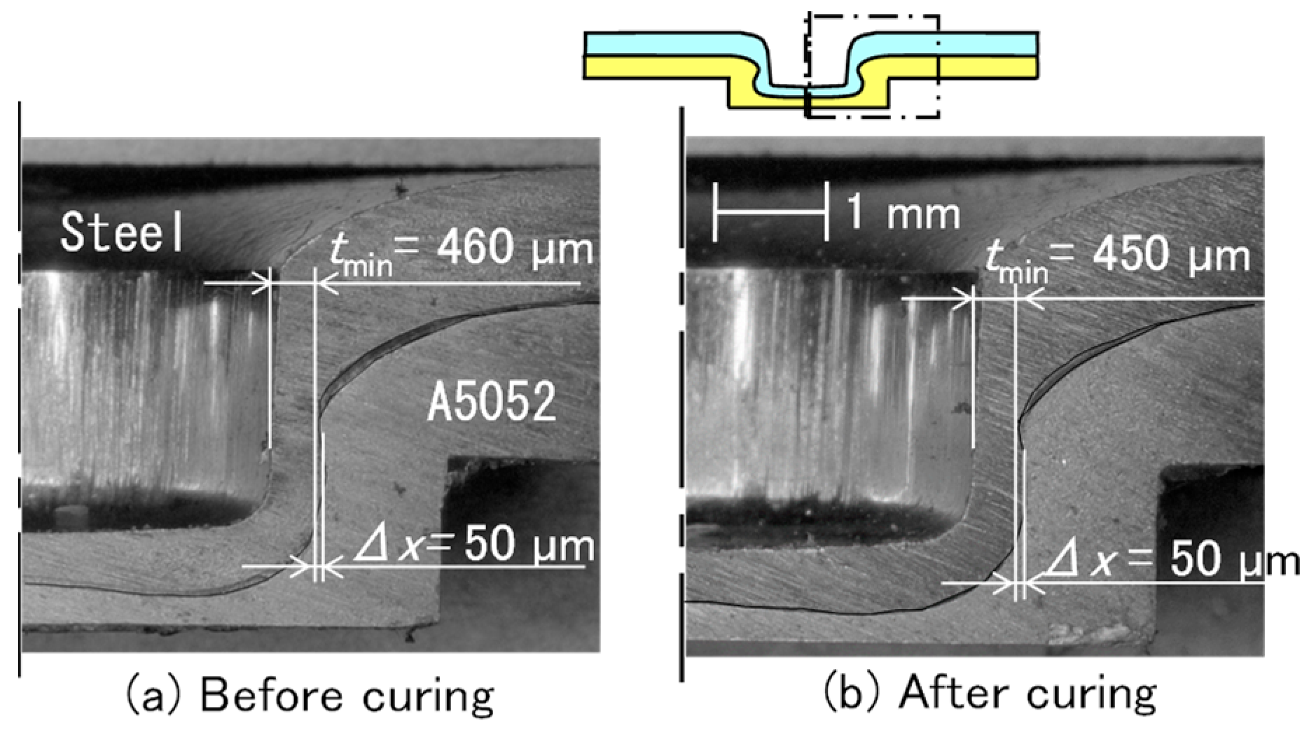
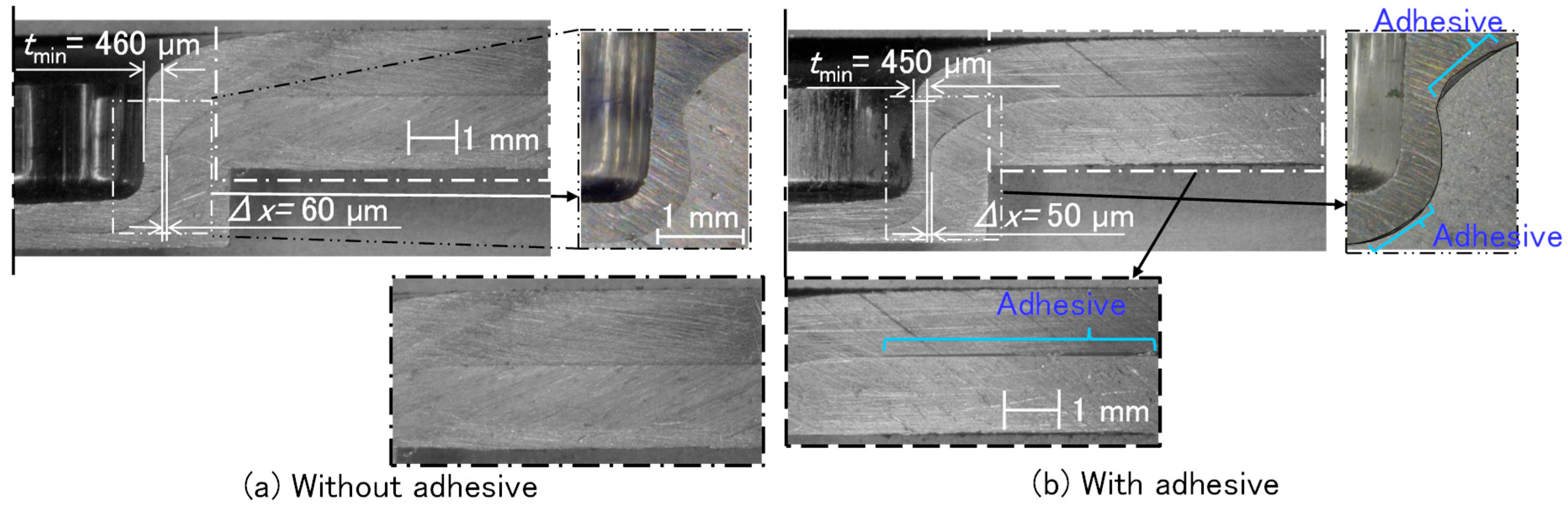
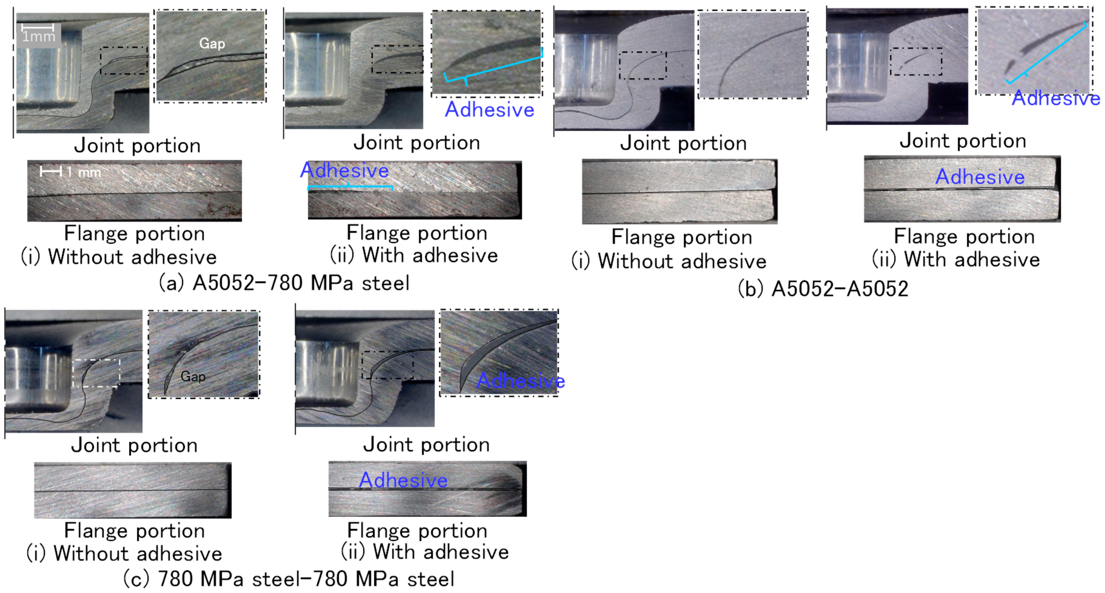
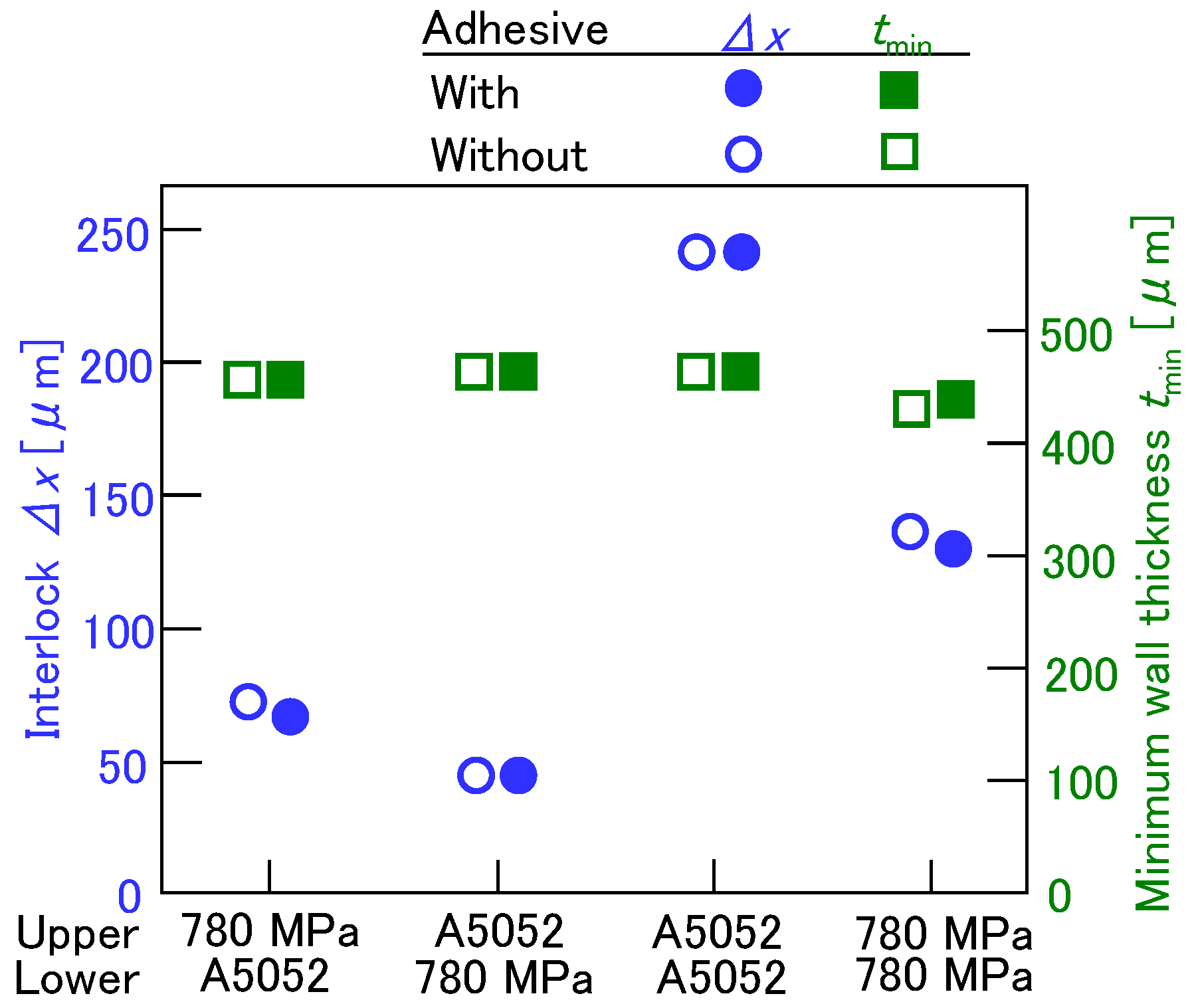
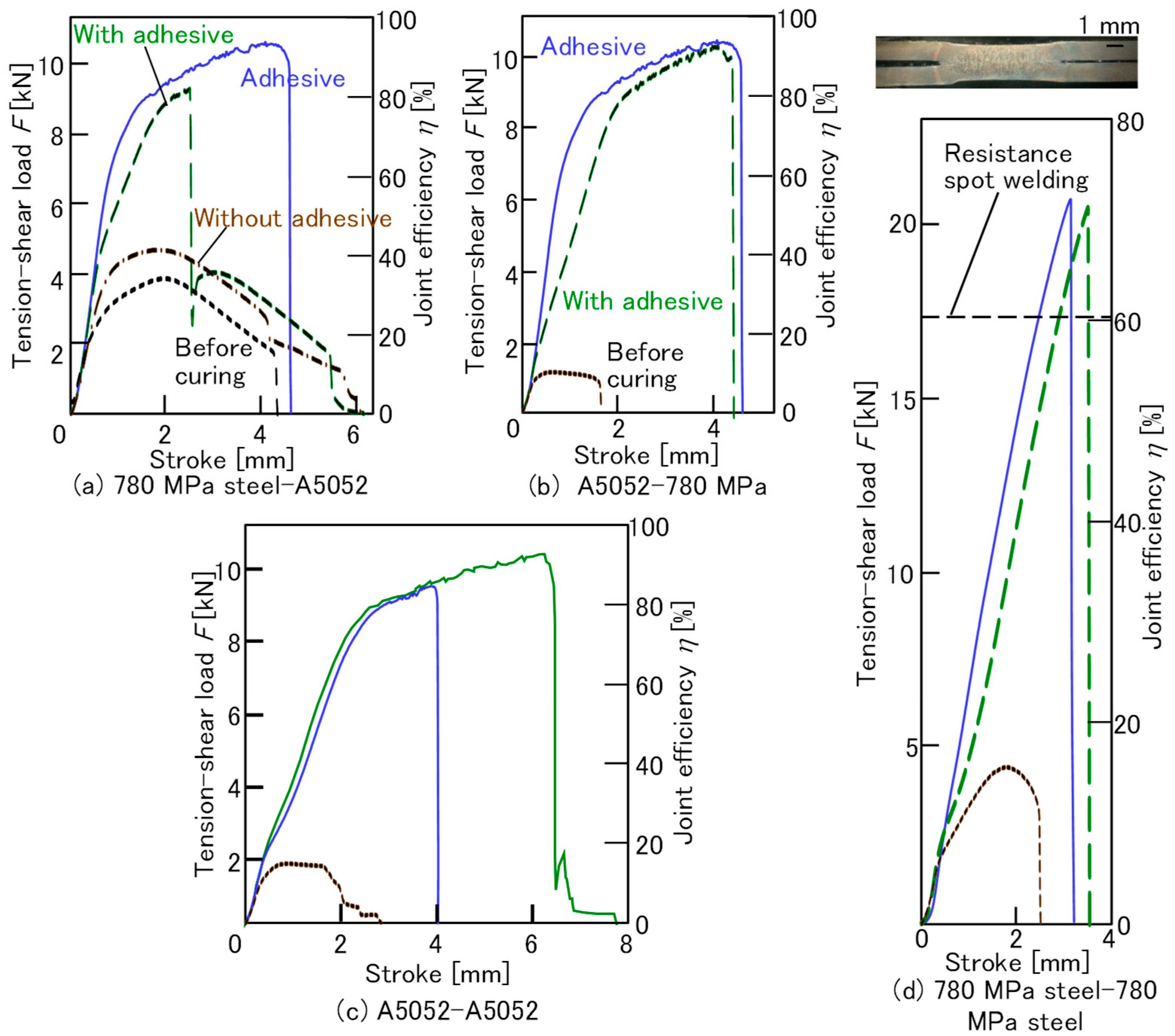
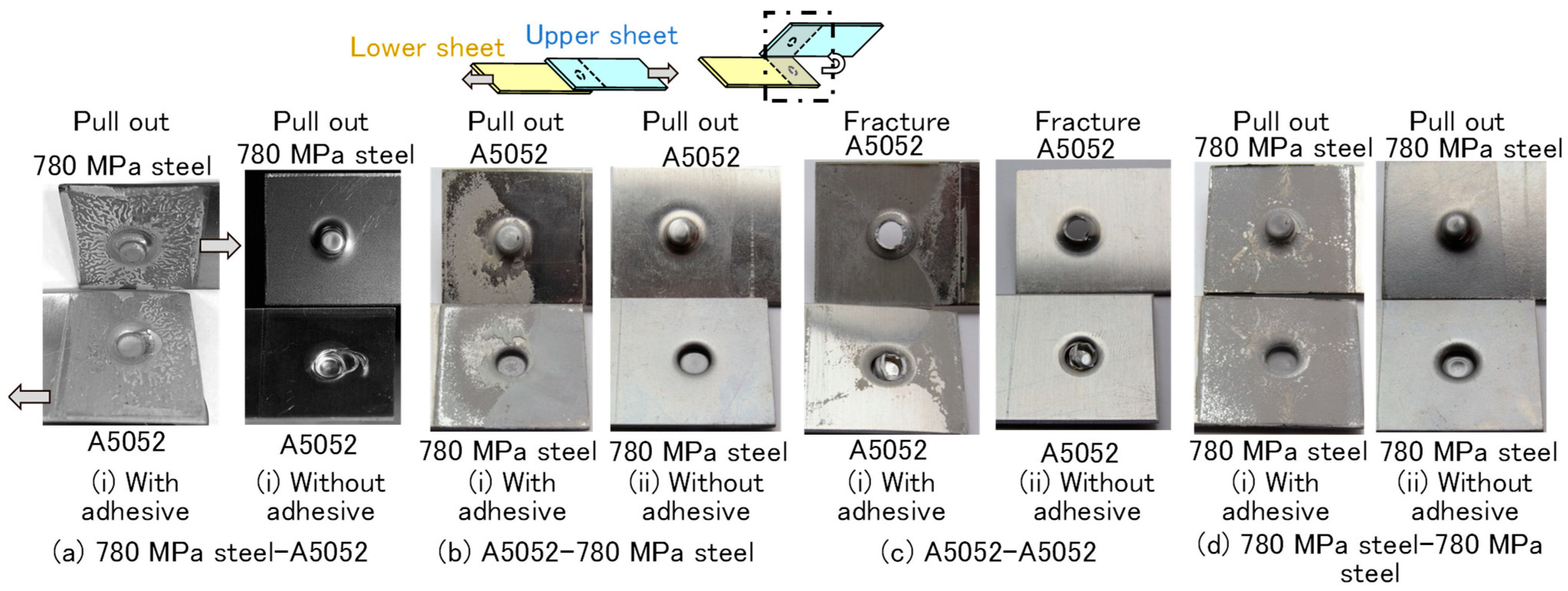
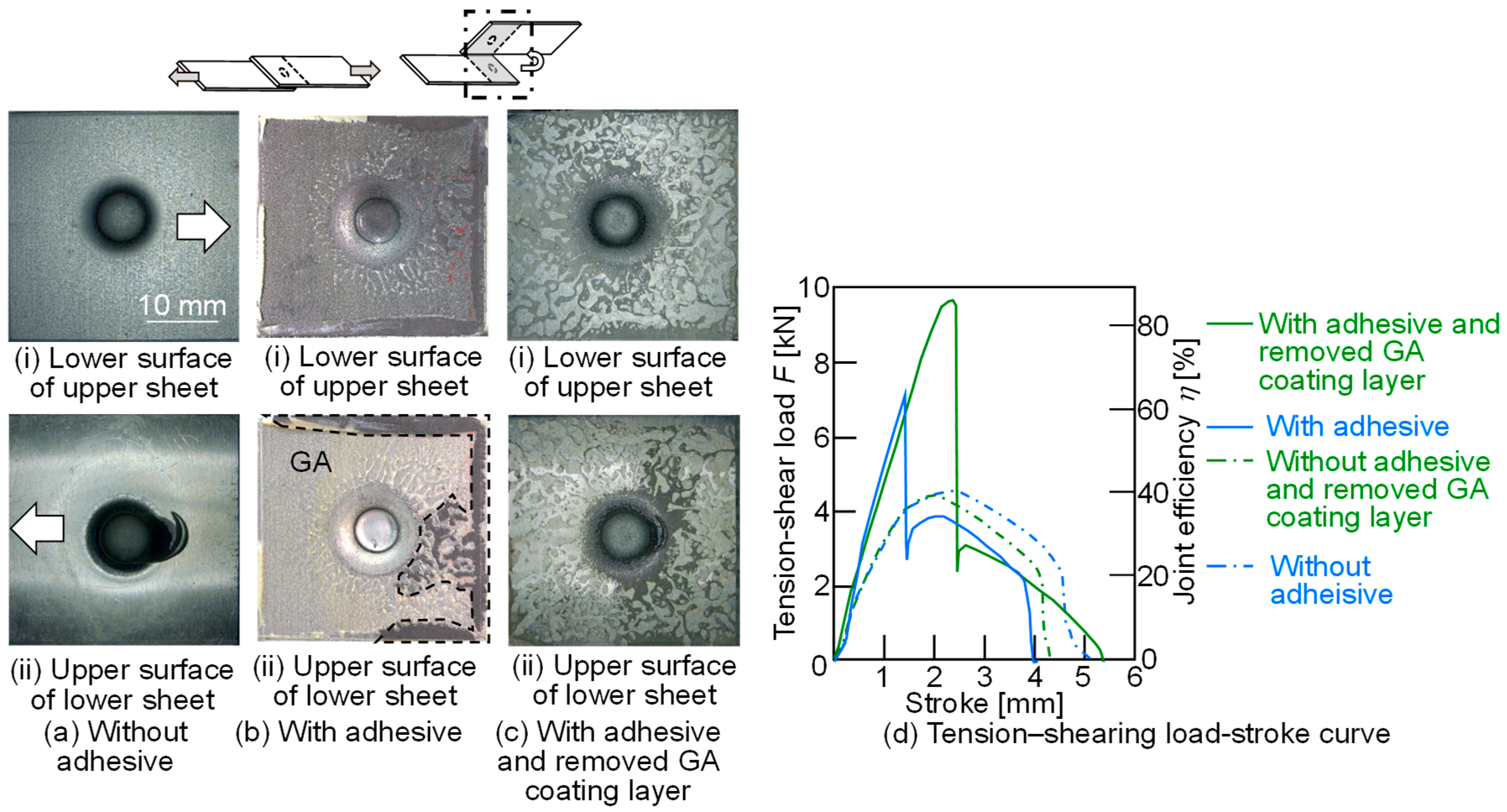
2.2. Experimental Results of Joined Sheets
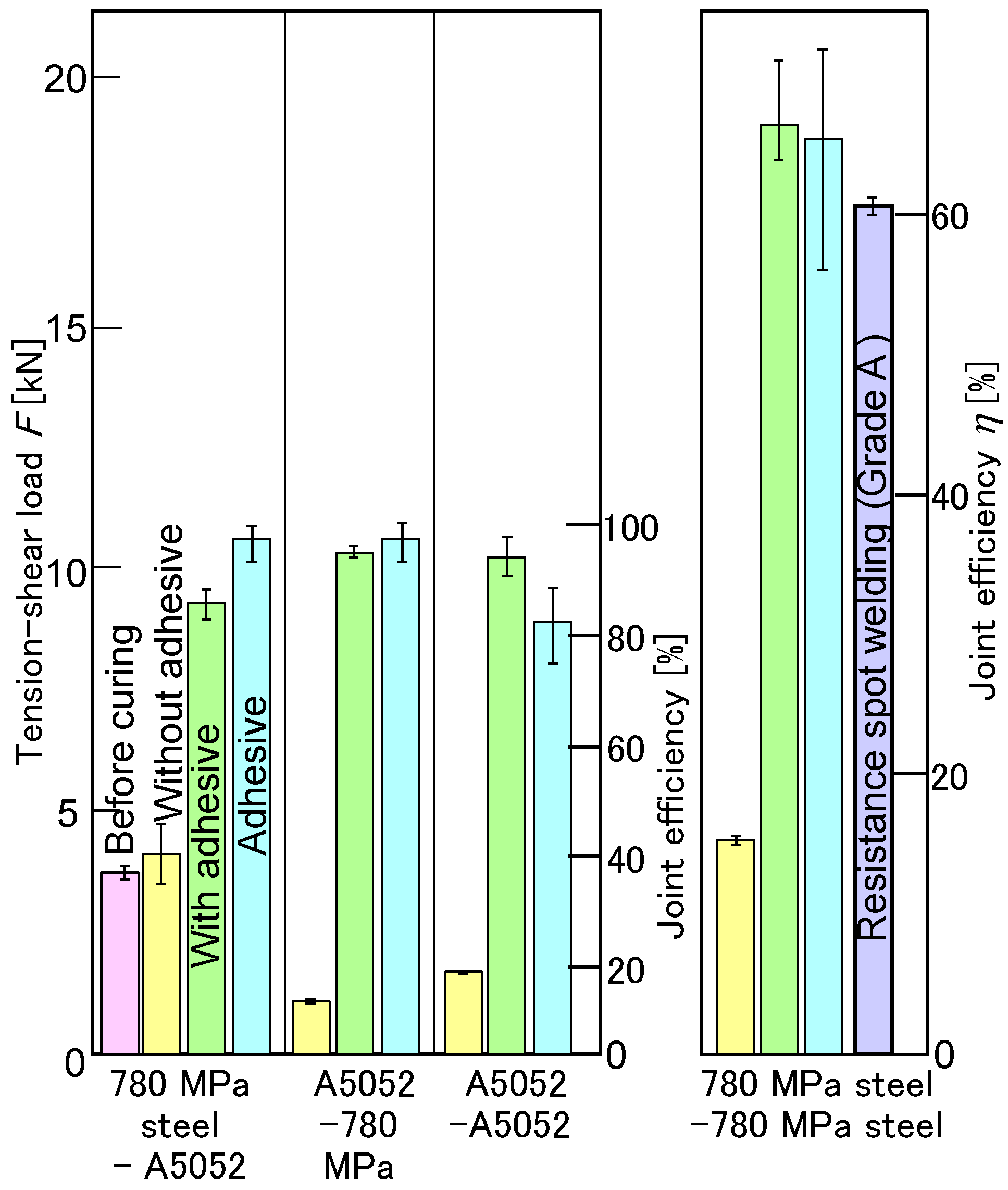
2.3. Experimental Results of Joint Strength
3. Clinch-Bonding for Upper 980 MPa Ultra-High-Strength Steel and Lower Aluminum Alloy Sheets
3.1. Sheet Materials and Clinching Methods
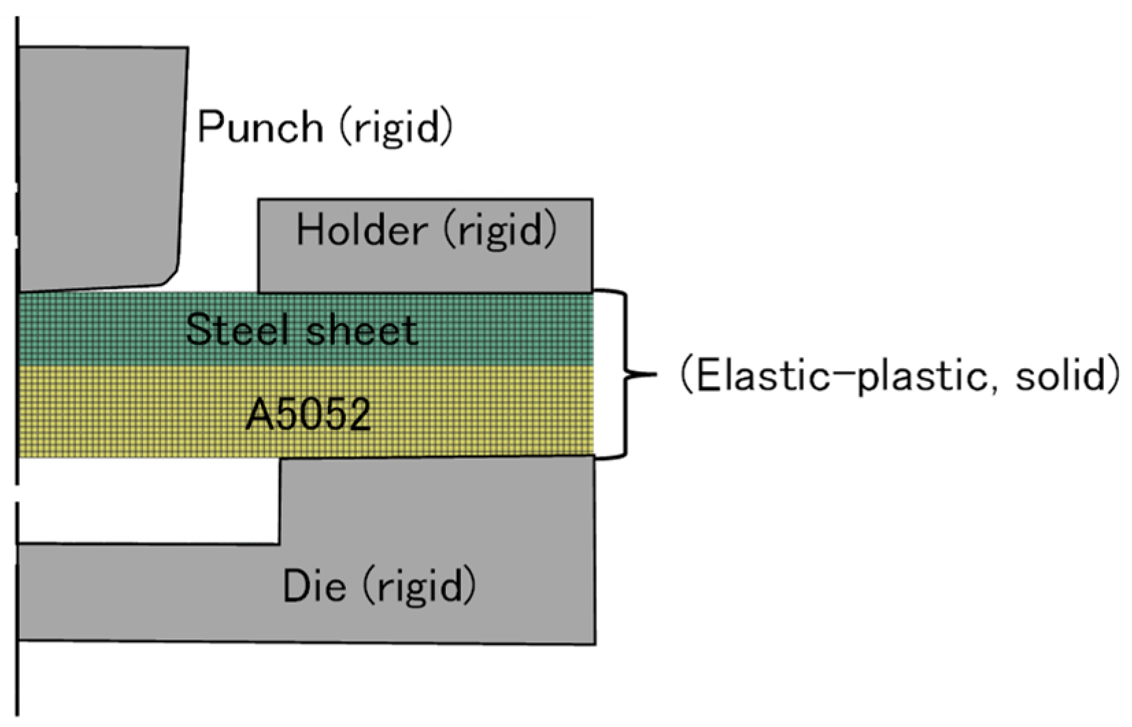
3.2. Methods and Conditions of Finite Element Simulation
3.3. Experimental and Simulated Results of Deforming Behaviors of Sheets
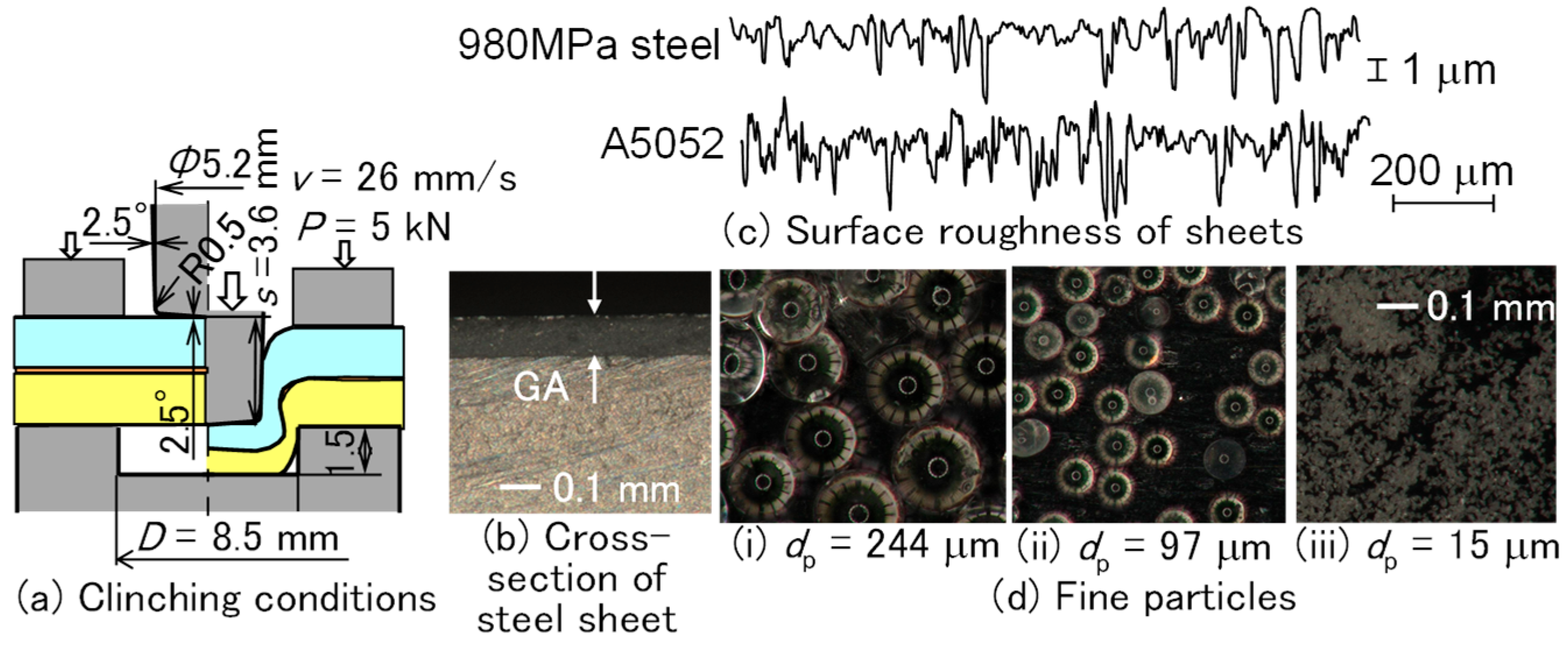
4. Clinch-Bonding for Upper Ultra-High-Strength Steel and Lower Aluminum Alloy Sheets Using Adhesive Containing Fine Particles
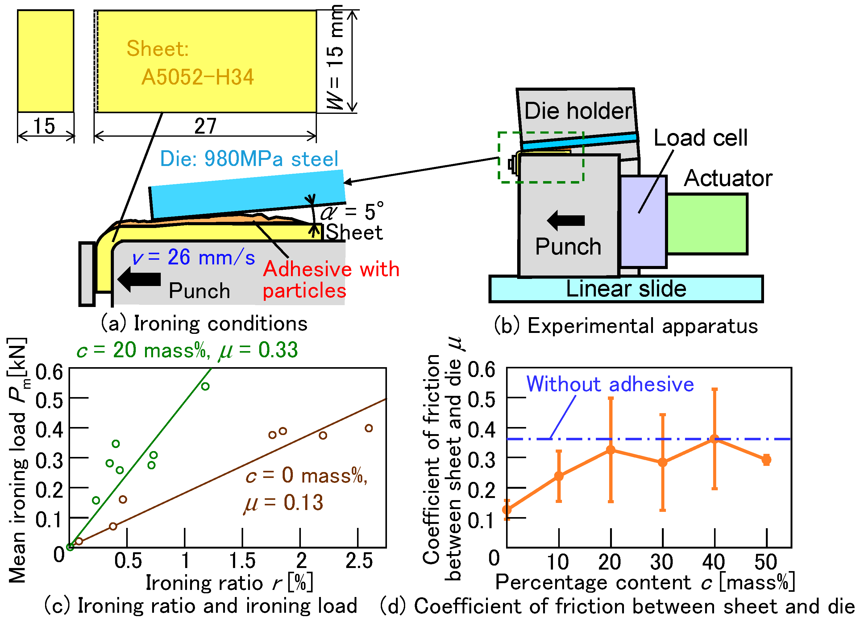
4.1. Clinching Methods Using Adhesive Containing Fine Particles
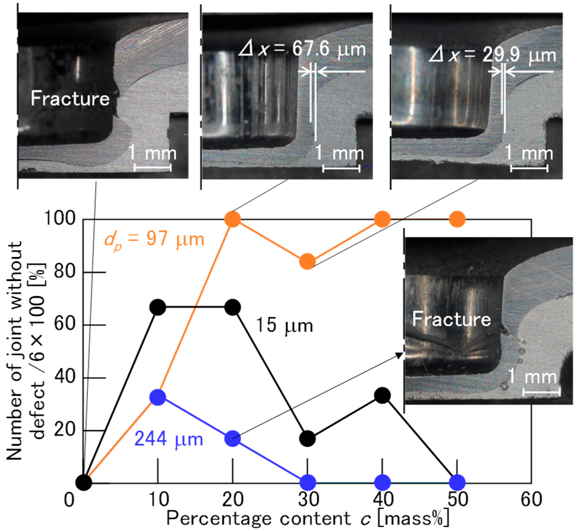
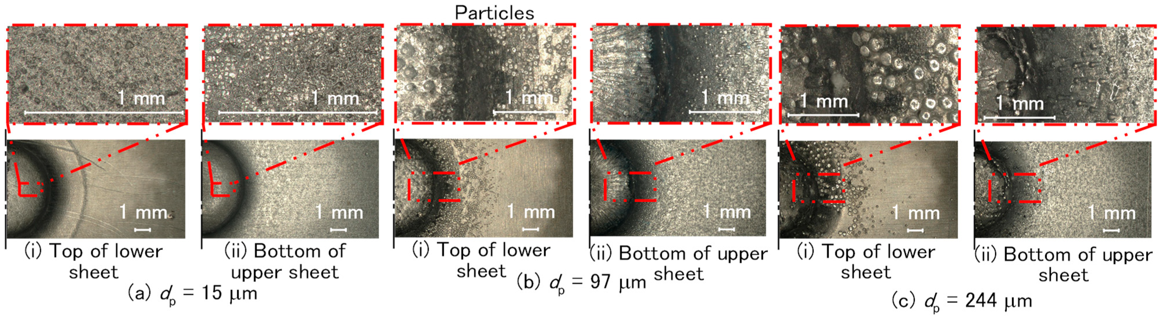
4.2. Experimental Results Using Adhesive Containing Fine Particles
4.3. Experimental Results of Joint Strength
5. Conclusions
- (1)
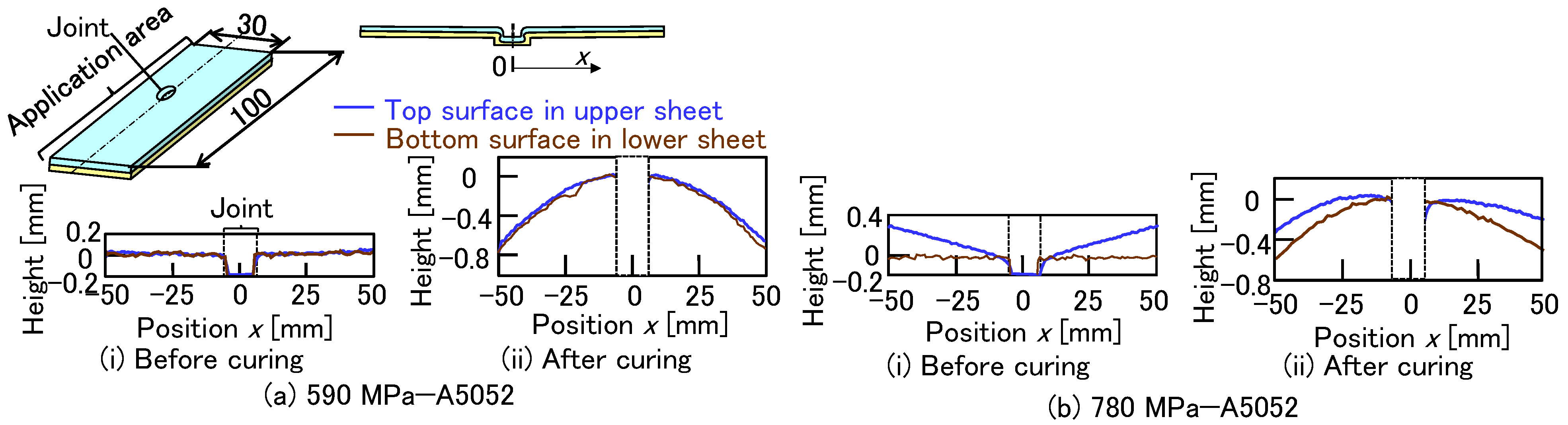
- In joining two sheets, including 780 MPa steel and A5052 sheets, the effect of the adhesive on the amount of interlock and the minimum thickness in the upper sheet was not significant; however, the effect of the sheet combination was observed. The maximum load with the adhesive exceeded 80% in joint efficiency. The maximum load for both 780 MPa sheets with the adhesive was approximately 65% in joint efficiency, which was the same as the joint efficiency of the adhesive-only joint.
- (2)
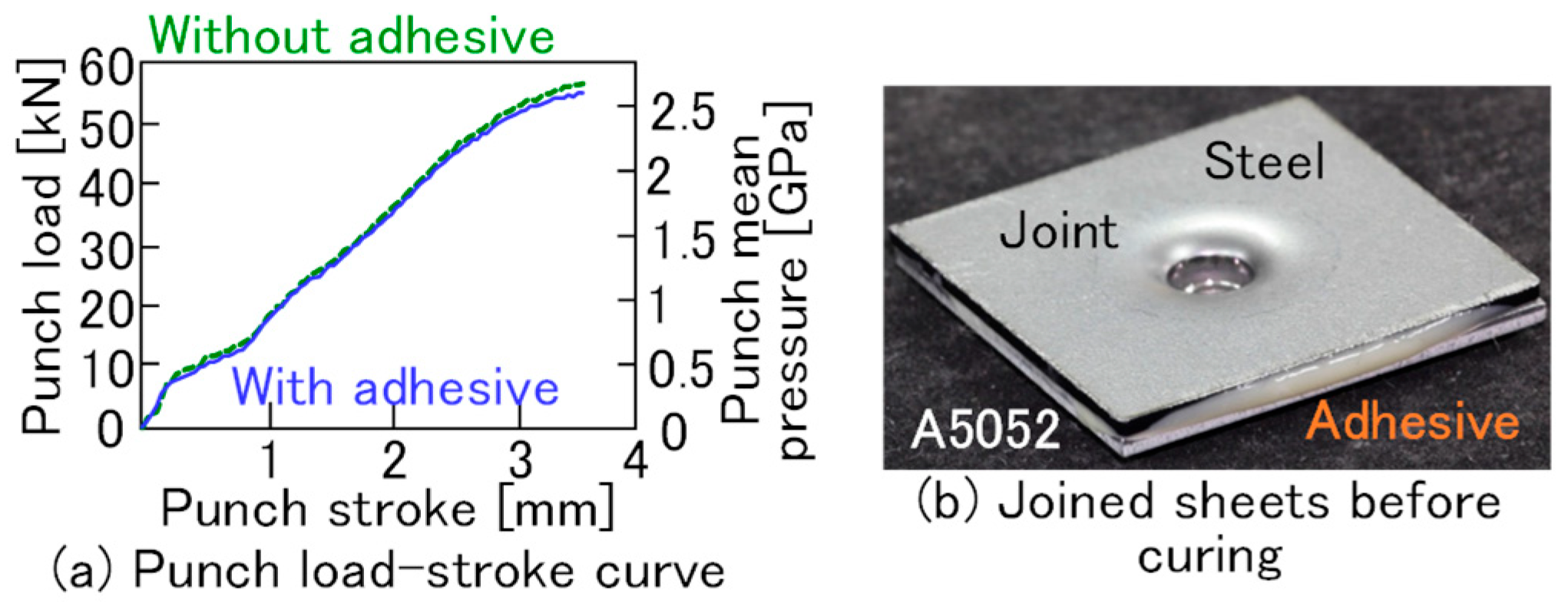
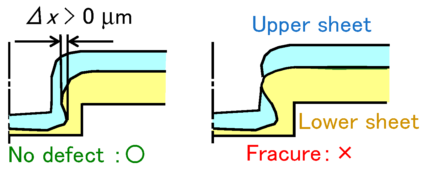
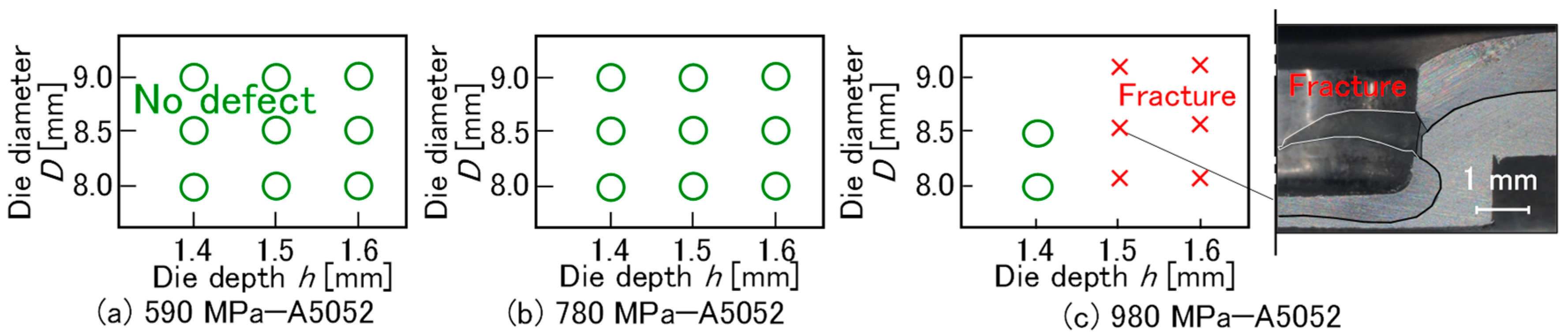
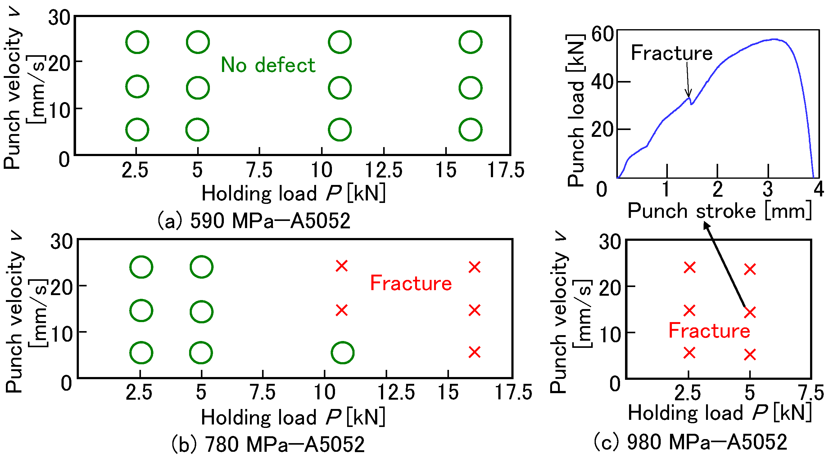
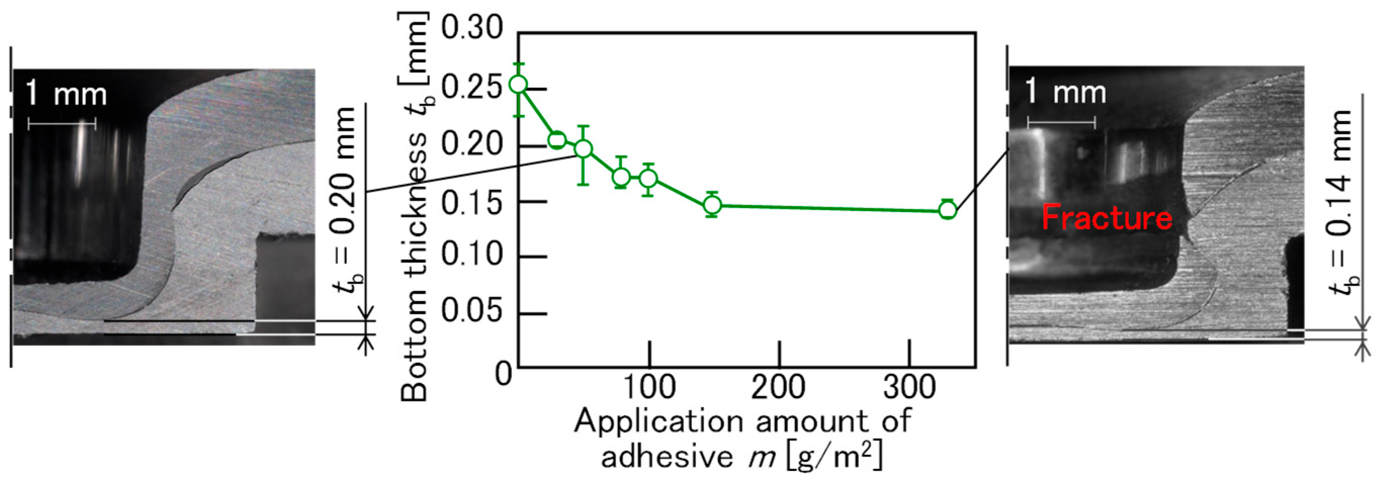
- Although the steel and A5052 sheets were joined without defects in many conditions in different die shapes, punch speeds, and holding forces in the 590 MPa and 780 MPa steel sheets, the conditions without defects were limited in the 980 MPa steel and A5052 sheets. Not only the insufficient ductility of the steel sheet but also the material flow of the sheets by the frictional effect between the sheets with the adhesive was influenced.
- (3)
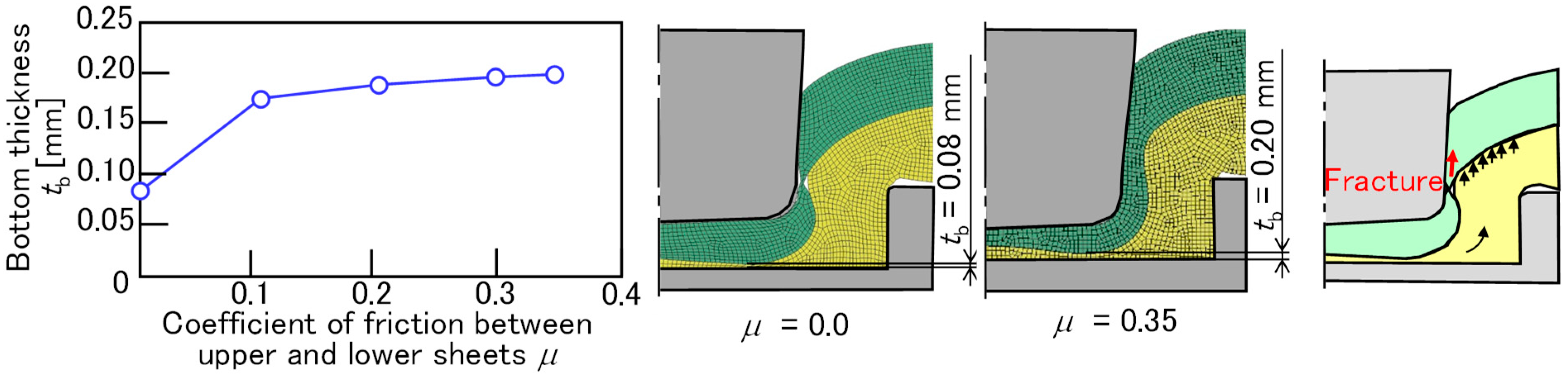
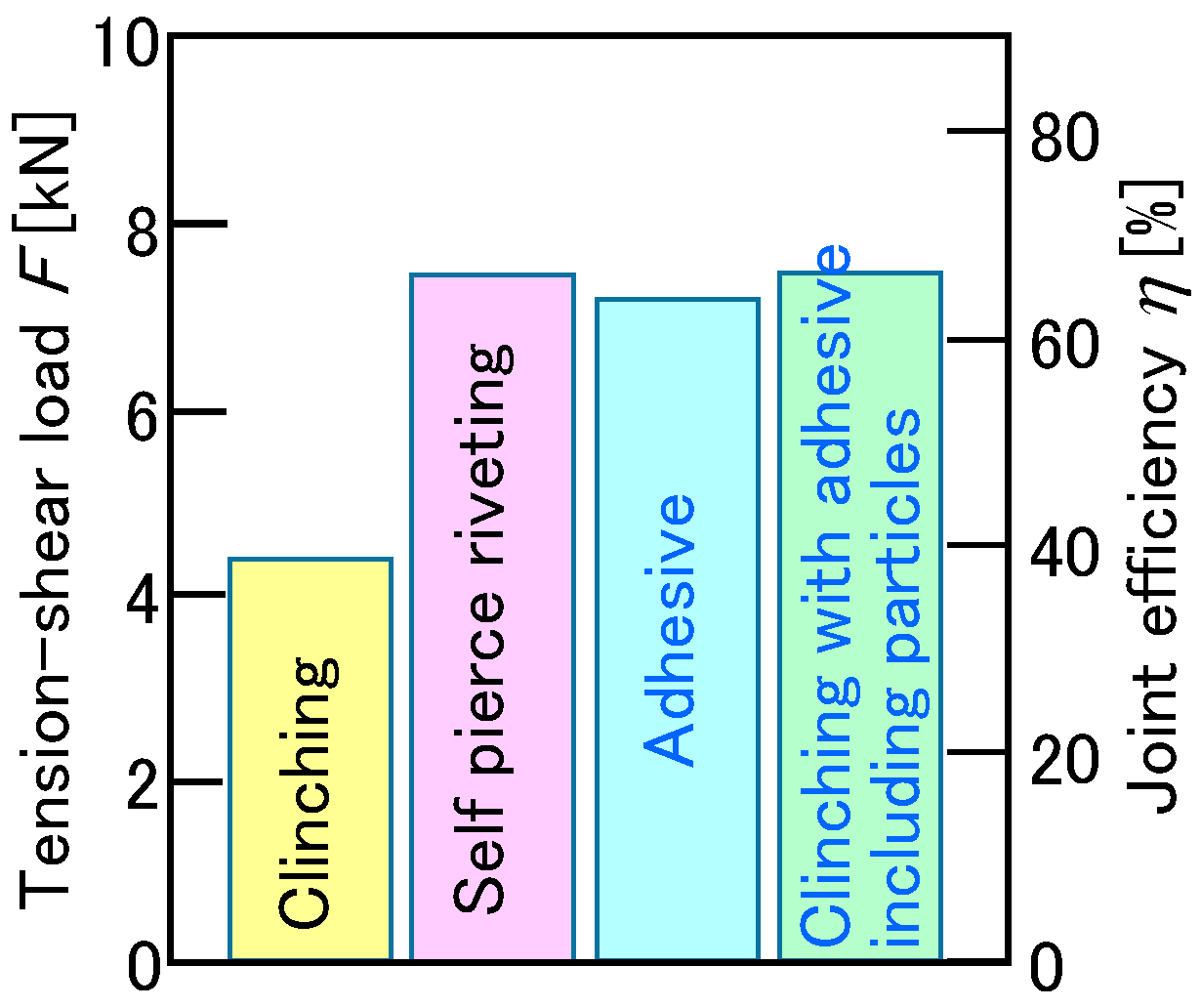
- In joining the upper 980 MPa ultra-high-strength steel and lower aluminum alloy sheets using clinching with the adhesive, the fracture of the steel around the sidewall of the punch could be prevented by reducing the material flow of the steel and aluminum alloy sheets using adhesive containing fine particles to increase friction. The friction coefficient under optimal conditions with the adhesive containing fine particles was close to that without the adhesive.
Author Contributions
Funding
Institutional Review Board Statement
Informed Consent Statement
Data Availability Statement
Acknowledgments
Conflicts of Interest
References
- Serino, S. The latest trend Body in white material to realise light weight and mass production. Aluminium 2022, 29, 9–12. [Google Scholar]
- Tabata, Y. Aluminum VISION 2050: Outline and implications. J. Jpn. Inst. Light Met. 2022, 72, 549–555. [Google Scholar] [CrossRef]
- Baser, T.A.; Umay, E.; Akinci, V. New trends in aluminum die casting alloys for automotive applications. Eurasia Proc. Sci. Technol. Eng. Math. 2022, 21, 79–87. [Google Scholar] [CrossRef]
- Trzepieciński, T.; Najm, S.M. Current trends in metallic materials for body panels and structural members used in the automotive industry. Materials 2024, 17, 590. [Google Scholar] [CrossRef] [PubMed]
- Watanabe, T.; Takayama, H.; Yanagisawa, A. Joining of aluminum alloy to steel by friction stir welding. J. Mech. Work. Technol. 2006, 178, 342–349. [Google Scholar] [CrossRef]
- Sun, J.; Yan, Q.; Gao, W.; Huang, J. Investigation of laser welding on butt joints of Al/steel dissimilar materials. Mater. Des. 2015, 83, 120–128. [Google Scholar] [CrossRef]
- Song, J.; Lin, S.; Yang, C.; Fan, C. Effects of Si additions on intermetallic compound layer of aluminum–steel TIG welding–brazing joint. J. Alloys Compd. 2009, 488, 217–222. [Google Scholar] [CrossRef]
- Qiu, R.; Satonaka, S.; Iwamoto, C. Effect of interfacial reaction layer continuity on the tensile strength of resistance spot welded joints between aluminum alloy and steels. Mater. Des. 2009, 30, 3686–3689. [Google Scholar] [CrossRef]
- Meschut, G.; Janzen, V.; Olfermann, T. Innovative and highly productive joining technologies for multi-material lightweight car body structures. J. Mater. Eng. Perform. 2014, 23, 1515–1523. [Google Scholar] [CrossRef]
- Porcaro, R.; Hanssen, A.; Langseth, M.; Aalberg, A. Self-piercing riveting process: An experimental and numerical investigation. J. Mech. Work. Technol. 2006, 171, 10–20. [Google Scholar] [CrossRef]
- Aslan, F.; Langlois, L.; Balan, T. Experimental analysis of the flow drill screw driving process. Int. J. Adv. Manuf. Technol. 2019, 104, 2377–2388. [Google Scholar] [CrossRef]
- He, X. Clinching for sheet materials. Sci. Technol. Adv. Mater. 2017, 18, 381–405. [Google Scholar] [CrossRef]
- Barnes, T.; Pashby, I. Joining techniques for aluminium spaceframes used in automobiles: Part II—Adhesive bonding and mechanical fasteners. J. Mech. Work. Technol. 2000, 99, 72–79. [Google Scholar] [CrossRef]
- Kalpakjian, S. Manufacturing Engineering and Technology, ch. 32, 70th ed.; Addison-Wesley: New York, NY, USA, 2014; p. 948. [Google Scholar]
- Himuro, K.; Sadai, A.; Matsui, K.; Sumida, H.; Yamamoto, K. Clarification of deterioration mechanism of structural adhesives by water absorption. Trans. Soc. Automot. Eng. Jpn. 2012, 43, 543. [Google Scholar] [CrossRef]
- Bartczak, B.; Mucha, J.; Trzepieciński, T. Stress distribution in adhesively-bonded joints and the loading capacity of hybrid joints of car body steels for the automotive industry. Int. J. Adhes. Adhes. 2013, 45, 42–52. [Google Scholar] [CrossRef]
- Balawender, T.; Sadowski, T.; Golewski, P. Numerical analysis and experiments of the clinch-bonded joint subjected to uniaxial tension. Comput. Mater. Sci. 2012, 64, 270–272. [Google Scholar] [CrossRef]
- Balawender, T.; Sadowski, T.; Golewski, P. Experimental and numerical analyses of clinched and adhesively bonded hybrid joints. J. Adhes. Sci. Technol. 2011, 25, 2391–2407. [Google Scholar]
- He, X.; Zhao, L.; Yang, H.; Xing, B.; Wang, Y.; Deng, C.; Gu, F.; Ball, A. Investigations of strength and energy absorption of clinched joints. Comput. Mater. Sci. 2014, 94, 58–65. [Google Scholar] [CrossRef]
- Hahn, O.; Meschut, G.; Bergau, M.; Matzke, M. Self-pierce riveting and hybrid joining of boron steels in multi-material and multi-sheet joints. Procedia CIRP 2014, 18, 192–196. [Google Scholar] [CrossRef]
- Ma, Y.; Akita, R.; Abe, Y.; Geng, P.; Luo, P.; Tsutsumi, S.; Ma, N. Mechanical performance evaluation of multi-point clinch adhesive joints of aluminum alloy A5052-H34 and high-strength steel JSC780. Automot. Innov. 2023, 6, 340–351. [Google Scholar] [CrossRef]
- Abe, Y.; Kishimoto, M.; Kato, T.; Mori, K.-I. Mechanical clinching of hot-dip zinc-aluminum alloy coated steel sheets. J. Jpn. Soc. Technol. Plast. 2010, 51, 592–596. [Google Scholar] [CrossRef]
- Mizushima, D.; Murakami, H. Effect of lubricant viscosity on peeling strength of mechanical clinching. J. Jpn. Soc. Technol. Plast. 2010, 51, 974–978. [Google Scholar] [CrossRef]
- Etemadi, S.; Hahn, O.; Roll, K. Simulation of hybrid joining technologies using the example of clinch-bonding. Key Eng. Mater. 2012, 504, 777–782. [Google Scholar] [CrossRef]
- Ma, Y.; Abe, Y.; Geng, P.; Akita, R.; Ma, N.; Mori, K.-I. Adhesive dynamic behavior in the clinch-bonding process of aluminum alloy A5052-H34 and advanced high-strength steel JSC780. J. Mech. Work. Technol. 2022, 305, 117602. [Google Scholar] [CrossRef]
- Martin, S.; Camberg, A.A.; Tröster, T. Probability distribution of joint point loadings in car body structures under global bending and torsion. Procedia Manuf. 2020, 47, 419–424. [Google Scholar] [CrossRef]
- Varis, J. Ensuring the integrity in clinching process. J. Mech. Work. Technol. 2006, 174, 277–285. [Google Scholar] [CrossRef]
- Tanabe, Y.; Aoki, H.; Yanai, H.; Matsumoto, Y.; Shibata, S. A study on the mechanical properties of caulked joints subjected to single shear. Collect. Struct. Eng. Pap. B 2004, 50B, 367–372. [Google Scholar]
- Pirondi, A.; Moroni, F. Clinch-bonded and rivet-bonded hybrid joints. application of damage models for simulation of forming and failure. J. Adhes. Sci. Technol. 2009, 23, 1547–1574. [Google Scholar] [CrossRef]
- Abe, Y.; Mori, K.; Kato, T. Joining of high strength steel and aluminium alloy sheets by mechanical clinching with dies for control of metal flow. J. Mech. Work. Technol. 2012, 212, 884–889. [Google Scholar] [CrossRef]
- JIS Z 2241:2022; Metallic Materials—Tensile Testing—Method of Test at Room Temperature. Japanese Standards Association: Tokyo, Japan, 2022.
- Tan, C.; Abe, Y.; Daodon, W.; Takahashi, N.; Mori, K.; Purbolaksono, J. Increase in ironing limit of aluminium alloy cups with lubricants containing nanoparticles. J. Mech. Work. Technol. 2016, 229, 804–813. [Google Scholar] [CrossRef]
- Abe, Y.; Sugiura, K.; Yamashita, T.; Mori, K.-I. Forward extrusion of aluminium alloy billet using oil containing fine ceramic particles. Procedia Manuf. 2018, 15, 240–248. [Google Scholar] [CrossRef]
- Masuda, M.; Murota, T. Kogyososeirikigaku; Yokendo: Tokyo, Japan, 1980; p. 206. [Google Scholar]

| Sheet | Thickness t [mm] | Tensile Strength [MPa] | Elongation [%] |
|---|---|---|---|
| 780 MPa steel | 1.20 | 799 | 19.2 |
| A5052-H34 | 1.50 | 249 | 10.5 |
| Combination | Upper Sheet | Lower Sheet | s [mm] | H [mm] | D [mm] |
|---|---|---|---|---|---|
| Dissimilar | 780 MPa steel | A5052-H34 | 3.6 | 1.5 | 8.5 |
| A5052-H34 | 780 MPa steel | 4.0 | 1.7 | 8.0 | |
| Similar | A5052-H34 | A5052-H34 | 3.9 | 1.7 | 8.75 |
| 780 MPa steel | 780 MPa steel | 3.6 | 1.7 | 8.5 |
| Sheet | Sheet | Thickness t [mm] | Tensile Strength [MPa] | Elongation [%] |
|---|---|---|---|---|
| Upper | 590 MPa steel | 1.20 | 574 | 24.8 |
| 780 MPa steel | 799 | 19.2 | ||
| 980 MPa steel | 1035 | 13.9 | ||
| Lower | A5052-H34 | 1.50 | 249 | 10.5 |
| Sheet | Thickness t [mm] | K [MPa] | n [-] |
|---|---|---|---|
| 980 MPa steel | 1.20 | 1406 | 0.13 |
| A5052-H34 | 1.50 | 411 | 0.11 |
Disclaimer/Publisher’s Note: The statements, opinions and data contained in all publications are solely those of the individual author(s) and contributor(s) and not of MDPI and/or the editor(s). MDPI and/or the editor(s) disclaim responsibility for any injury to people or property resulting from any ideas, methods, instructions or products referred to in the content. |
© 2025 by the authors. Licensee MDPI, Basel, Switzerland. This article is an open access article distributed under the terms and conditions of the Creative Commons Attribution (CC BY) license (https://creativecommons.org/licenses/by/4.0/).
Share and Cite
Abe, Y.; Tatara, Y.; Hosokawa, T.; Yamauchi, R. Clinch-Bonding Process for Ultra-High-Strength Steel and A5052 Aluminum Alloy Sheets. Materials 2025, 18, 3556. https://doi.org/10.3390/ma18153556
Abe Y, Tatara Y, Hosokawa T, Yamauchi R. Clinch-Bonding Process for Ultra-High-Strength Steel and A5052 Aluminum Alloy Sheets. Materials. 2025; 18(15):3556. https://doi.org/10.3390/ma18153556
Chicago/Turabian StyleAbe, Yohei, Yu Tatara, Takahiro Hosokawa, and Ryoto Yamauchi. 2025. "Clinch-Bonding Process for Ultra-High-Strength Steel and A5052 Aluminum Alloy Sheets" Materials 18, no. 15: 3556. https://doi.org/10.3390/ma18153556
APA StyleAbe, Y., Tatara, Y., Hosokawa, T., & Yamauchi, R. (2025). Clinch-Bonding Process for Ultra-High-Strength Steel and A5052 Aluminum Alloy Sheets. Materials, 18(15), 3556. https://doi.org/10.3390/ma18153556