Abstract
The current study demonstrates the buckling properties of composite laminates reinforced with MWCNT fillers using a novel higher-order shear and normal deformation theory (HSNDT), which considers the effect of thickness in its mathematical formulation. The hybrid HSNDT combines polynomial and hyperbolic functions that ensure the parabolic shear stress profile and zero shear stress boundary condition at the upper and lower surface of the plate, hence removing the need for a shear correction factor. The plate is made up of carbon fiber bounded together with polymer resin matrix reinforced with MWCNT fibers. The mechanical properties are homogenized by a Halpin–Tsai scheme. The MATLAB R2019a code was developed in-house for a finite element model using C0 continuity nine-node Lagrangian isoparametric shape functions. The geometric nonlinear and linear stiffness matrices are derived using the principle of virtual work. The solution of the eigenvalue problem enables estimation of the critical buckling loads. A convergence study was carried out and model efficiency was corroborated with the existing literature. The model contains only seven degrees of freedom, which significantly reduces computation time, facilitating the comprehensive parametric studies for the buckling stability of the plate.
1. Introduction
Composite materials are created by the combination of at least two materials with varying mechanical and physical properties. As compared to their individual components, composite materials exhibit superior material properties, because they tend to minimize the weakness and improvise the strength of its constituent materials. Their advantages include enhanced strength-to-weight ratios and corrosion resistance, making them ideal for engineering applications like automobile, aerospace, biomedical, and marine structures. Since 1960, composites have found extensive application in engineering structures due to their ability to be customized for superior mechanical and chemical properties compared to its constituents. However, delamination is a major challenge in composite material laminates and this can be reduced by the addition of reinforcing MWCNT fibers.
Composite materials are prone to buckling when used as laminates under the action of compressive loading. The equilibrium displacement of these thin and slender laminated structures buckles when the compressive load increases beyond a certain critical load. The anisotropic nature of the composite laminates and additional non-homogeneity due to MWCNT fibers increases the complexity of the microstructure. The Halpin–Tsai (H-T) Model [1] provides a simplified semi-empirical material homogenization scheme to estimate the mechanical properties characterizing the composite material. Nonetheless, there are number of design parameters that present major challenges in conducting the structural analysis of the composite materials. Consequently, many design and analysis techniques for composite structures have been increasingly explored for comprehensive evaluation of their mechanical properties.
Exact three-dimensional (3D) theories [2,3,4,5] directly addressed the full three-dimensional equations of elasticity. And hence, they predicted the displacement and stresses of the plates under external loading with great accuracy. The 3D exact plate theory offers a more accurate representation of plate behavior and the results obtained from these theories can serve as the benchmark for the other research works. The complexity of the solutions and requirement of large computations often limit the application of this theory for simple geometries and loading conditions. The complexity of the three-dimensional equations of elasticity can be reduced either by layerwise partition of the structure or by decreasing the degrees of freedoms of structure into equivalent single layer. In layerwise theories, variables are dependent on the layer and each layer is analyzed separately. Boundary conditions are satisfied at the interface of each layer (Robbins and Reddy [6], Li [7], Rakočević et. al. [8], Goswami and Becker [9]). Computations and accuracy are reduced when compared to 3D exact plate theories. In equivalent single layer (ESL) theories, calculations are limited to mid-plane displacements and all the other displacements are modelled as the function of its thickness coordinates and displacement of the mid-plane. Using ESL theories, computations are reduced drastically.
However, the reliability of the results is reliant on the type of functions employed for modelling.
ESL theories like Kirchhoff’s classical plate [10] theory omits the effect of transverse shear stress completely. This theory produces acceptable outcomes for thin plates while the impact of transverse shear is noticeable for thick and moderately thick plates. As a result, the stresses and displacement calculated using this theory has some errors, like for moderately thick plates, for instance, CLPT (Classical Laminate Plate Theory) overpredicts the buckling. To address this issue, the first-order shear deformation theory (FSDT) is suggested. FSDT, founded on plate theory of Reissner [11] and Mindlin [12], takes an independent field variable for the rotation of the transverse normal vector in order to consider the transverse shear stress effect. However, this theory results in finite transverse shear stress on plate surface. In order to adequately fulfill the traction-free boundary condition at both the upper and lower plate surfaces, a shear correction factor is thus added. However, determining the shear correction factor value for real-world issues is challenging, since it is mostly dependent upon loading circumstances, boundary conditions, stacking scheme, geometry, and complex material characteristics.
Second-order shear deformation theories (Khdeir and Reddy [13], Shahrjerdi et. al. [14]) gave marginally improved results for the stresses and displacement when compared to FSDT. However, the requirement of a shear correction factor still existed, restricting its computational advantages. Third-order shear deformation theories are developed to eliminate the necessity for shear correction factors, accurately account for cross-sectional warping, as well as achieve a realistic representation of the variations in transverse shear strains and stresses. These theories are refined by using cubic polynomial (Shi [15], Aagaah et al. [16], Ferreira et al. [17]) or orthogonal polynomial like Legendre polynomials (Carrera et al. [18], Pagani [19], Verma et al. [20]) and reduce the number of variables to ensure traction free boundary conditions at the upper and lower plate surface and model the flexural behavior of the plate. Some non-polynomial shear deformation functions like trigonometric (Thai and Vo [21], Ferreira et al. [22], Wang and Wu [23]), exponential (Mantari et al. [24], Khorshidi and Fallah [25]), hyperbolic (Meiche et al. [26], Grover et al. [27], Thai et al. [28]), and inverse trigonometric functions (Nguyen et al. [29], Grover et al. [30]) are also utilized for modelling. The infinite differentiability of these functions and peculiar nonlinearity makes them more suitable for capturing the accurate behavior of the transverse shear stresses and strain without increasing the number of additional parameters for calculation. This results in increase in computational efficiency of the model without compromising with the accuracy of the solutions.
The differential equation for the plate under various loading conditions is solved using Fourier series expansions like Navier solutions (Farahmand et. al. [31], Levinson and Cooke [32]) and Levy solutions (Mohammadi et al. [33], Thai et al. [34]), or by using approximate solutions for series of functions like the Galerkin method and Reyleigh–Ritz method (Lam et al. [35], Liew [36]). While analytical methods provide exact solutions, they are often limited to simple geometries and loading conditions. For complex geometries and boundary conditions, various numerical methods are more practical. Additionally, these transverse strains involve normal and transverse shear stresses, which, due to equilibrium considerations, exhibit continuity at every layer interface. These conditions require solutions to satisfy C1-continutity conditions. These criteria can be modelled by using layer-independent Murakami’s Zig-Zag Functions (Carrera [37], Brischetto et al. [38]) or by using meshfree methods (Liew et al. [39], Belinha et al. [40]), where a set of scattered nodes is used to approximate the solutions. This makes them particularly useful for problems with complex geometries, large deformations, and moving boundaries. However, the implementation of C1-contintuity of displacement and slopes of zig-zag theories or meshless techniques requires use of complex algorithms. Therefore, simple C0-continuity finite element solutions were developed and refined for this purpose. Their simplicity and efficacy to model complex geometric, loading and boundary conditions accurately is remarkable.
Lei et al. [41] conducted a buckling analysis on composite plates reinforced with carbon nanotubes (CNT-RC) with functionally graded (FG) properties by employing a set of mesh-free kernel particle functions and FSDT. Shen and Zhu [42] investigate the phenomenon of buckling and post-buckling in nanocomposite plates subjected to uniaxial compression, specifically focusing on the presence of functionally graded (FG) nanotube reinforcements. An investigation by Meng and Gardner [43] explored the stability of circular hollow section (CHS) columns, focusing on both normal and high strength steel through experimental and numerical methods. The deformation behavior of a composite laminated plate reinforced with carbon nanotubes (CNTs) simulations to investigate different types of carbon nanotube (CNT) distributions was examined by Lei et al. [44]. Zhang [45] studied the buckling characteristics of nanocomposite plates featuring polygonal platforms subjected to in-plane loads.
The study conducted by Srivastava and Kumar [46] examined the buckling and post-buckling characteristics of a nanocomposite plate containing randomly oriented carbon nanotubes in magnesium (Mg) under uniaxial compression. Kiani [47] investigated the issue of post-buckling in composite plates that were reinforced with CNTs and exposed to a homogeneous thermal stress. Thai and Kim [48] proposed the utilization of the third-order higher-order shear deformation theory (HSDT) to derive a closed-form solution for the buckling analysis of a thick functionally graded (FG) plate resting on an elastic foundation. Assessments on the free vibration and buckling characteristics of laminated non-rectangular plates reinforced with carbon nanotubes (FG-CNTR) were conducted by Civalek and Avcar [49], who employed a four-noded straight-sided transformation approach. An analytical model involving small-strain, moderate-rotation shell theory in conjunction with a linearly viscoelastic material law was adopted by Liu et al. [50].
Literature reviews showed that numerous shear deformation theories have been developed for modelling the composite laminate. However, for efficient and simplistic modelling of the composite laminates reinforced with MWCNT fibers, there is a need of novel HSDT, which can accurately predict the buckling behavior of MWCNT fiber interaction with composite laminates. The proposed equivalent single layer HSDT is accurate, simple for implementation, and increases the computational speed. The proposed mathematical formulation ensures C0-continutity of displacements, which increases its simplicity in formulation and implementation. Inhouse code written in MATLAB (R2019a) is used to write the algorithm of the mathematical formulation for the comprehensive evaluation of the plate buckling behavior of MWCNT-added composite laminate. Excellent convergence has been observed in the critical buckling loads of the model and the obtained results were corroborated with the findings from previous publications and have been found to be accurate. A parametric study has been performed on the model for the comprehensive evaluation of models and to understand the effect of MWCNT fibers on composite laminates.
2. Mathematical Formulation
2.1. Composite Laminate Geometry
The geometrical parameters of the MWCNT-added laminated composite, including length (a), width (b), and thickness (h), are illustrated in Figure 1. The coordinates x and y are employed for in-plane placement, whereas z is utilized for locating in the thickness direction. The fiber orientation angle is measured from the major axis (x-axis) in a clockwise manner. The laminate number and fiber orientation are supplied in order to analyze the composite laminate.
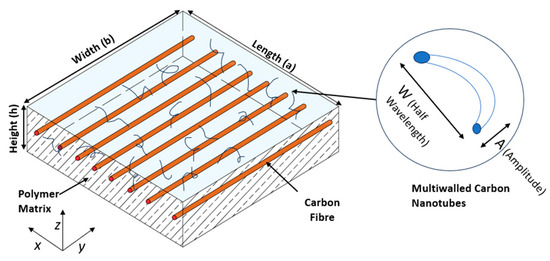
Figure 1.
Composite laminated epoxy resin and carbon fiber polymer matrix composite incorporating MWCNT additions within the matrix.
2.2. Material Homogenization Scheme
The H-T model governs the mechanical properties characterizing the MWCNT-reinforced polymer matrix, accounting for agglomeration, orientation, and waviness. The mechanical parameters (δ) of the composite lamina are derived from the characteristics of MWCNT reinforcements and the fiber-polymer matrix composite, as outlined in the methodology of Georgantzinos et al. [51]. The elastic modulus characterizing the polymer matrix reinforced with multi-walled carbon nanotubes () is presented below:
In this context, Em represents the elastic modulus of the polymer matrix, Vcnt denotes the volume fraction of multi-walled carbon nanotubes (MWCNTs), whereas R corresponds to the ratio of the length to the radius of the MWCNTs. The expression below can be used to determine parameter δ:
Waviness corresponds to parameter fw, as delineated in Equation (3), where A denotes the MWCNT bend amplitude, whereas W signifies its half-wavelength. The stochasticity of MWCNT orientation governs the parameter fr. If the lamina thickness is greater than MWCNT length, fr = 1/3 indicating slight orderliness; if not, fr = 1/6, which indicates large randomness. MWCNT aggregation is represented in Equation (4) by fa, where α and β describe the degree of CNT agglomeration, α is set at 10 and β at 0.9 for this research work.
The Poisson ratio, υ, corresponding to a polymer matrix reinforced with MWCNT can be considered equivalent to that of the pure polymer matrix, that is, υm-cnt = υm. Given the uniform distribution of MWCNTs, the polymer matrix added with MWCNT functions is a material with quasi-isotropic properties. The shear modulus characterizing the polymer matrix reinforced with multi-walled carbon nanotubes () is calculated in the following way:
where the and represents the in-plane Young’s modulus and Poisson’s ratio of elasticity. And , , and correspond to the Young’s modulus, the volume fraction and Poisson’s ratio of fiber, respectively. Equation (8) can be used to determine additional mechanical properties, where P may denote the transverse shear moduli (G13 and G23), in-plane shear modulus (G12), transverse Poisson ratio (υ23), and transverse modulus of elasticity (E2) whereas Pm-cnt may refer to material properties of the polymer matrix reinforced with MWCNT. The parameter ξ (reinforcing factor) equals 2 for E2 and ξ equals 1 for υ23, G12, and G23. Equation (9) is used to ascertain parameter η (experimental factor).
2.3. Displacement Field Model
The displacement fields in the current HSDT are delineated as follows:
Five fundamental nodal unknowns, including u, v, w, ϕsx, and ϕsy, constitute the displacement fields. Additionally, u, v, and w represent the displacements on the mid-plane of the plate along the x-, y-, and z-axes, respectively. In turn, ϕsx and ϕsy denote the rotation of the plate’s transverse normal about the y-axis and x-axis, respectively. The distribution of transverse shear strain over the plate’s thickness is delineated by the form function ψ(z), which combines polynomial and hyperbolic functions.
The derivatives of out-of-plane first-order provide challenges as the strain expressions will include second-order derivatives, necessitating the enforcement of C1 continuity. The C1 continuity criteria are intricate and challenging to simulate. Consequently, the out-of-plane derivatives are replaced by supplementary rotating unknowns, θbx and θby, to guarantee C0 continuity in the finite element modeling. The supplementary degrees of freedom are artificially restricted by integrating Constraint Equations (14) and (15) into the computation of the system’s strain energy.
The revised displacement fields Equations (14) and (15) can be expressed as follows:
Consequently, each node at the midplane comprise seven total nodal unknowns, in turn, in the formula below may be used to express the midplane displacement vector:
2.4. Strain Displacement Relationship
The equations below can be employed to express the strain-displacement relationship, derived from the differentiation of the displacement field equations, is articulated as follows:
These stresses may be expressed as the product of the midplane nodal unknowns and their derivatives, which vary across the plane, ϵo, as follows:
2.5. Constitutive Equation Ignoring Thickness Stretching (εzz = 0)
The constitutive equations employed in the analysis of MWCNT-reinforced composite laminates and nonlinear buckling analysis disregard the influence of thickness stretching, with the stress-strain relationship defined by the constitutive relationship presented in Equation (25).
The Q[ij] constants are derived from the modulus of elasticity E(z) as well as the Poisson ratio υ(z) utilizing the formulas in Equations (26)–(28)
2.6. Derivation of the Governing Equation of the Plate
The strain energy (U) of the plate may be articulated using strain ε and stress σ as follows:
Equation (30) simplifies the calculation of [D], the material rigidity matrix that correlates the influence of material property variations throughout the thickness to the mid-plane. It is articulated as follows:
The critical buckling load along the x- and y-axes is denoted as Nx and Ny, respectively, while Nxy signifies shear buckling. The total work performed by external compressive pressures exerted on the edges of the plate is as follows:
Equation (31) can be reformulated as Equation (32), where N represents the compressive force matrix and [Zb] denotes the thickness coordinate matrix for buckling, both delineated in the Appendix A. The buckling strain vector ϵb is defined as ϵb = {∂w/∂x, ∂w/∂y}.
The geometric rigidity matrix [D] is derived via the compressive stress matrix [N] and the thickness coordinate matrix [Zb] provided in the Appendix A. This matrix facilitates the application of the suggested HSDT as a comparable single-layer theory to convert the three-dimensional domain into a two-dimensional domain for analytical purposes.
The utilization of the virtual work principle concerning the strain energy, U, accumulated as a result of internal strains in the composite laminate, alongside the work necessary to impose the artificial constraint, C, as well as the external work induced by compressive stresses on the plate, V, results in the subsequent governing equation.
2.7. Finite Element Formulation
The formulation of the isoparametric finite element method for analyzing functionally graded material plates utilized nine-noded isoparametric Lagrangian shape functions. The employment of a nine-node element facilitates the implementation of a complete integration strategy. The shape functions utilized in the formulation are specified in Equation (35).
The midplane displacements at each node can be expressed as a linear combination of the nodal unknowns (Xi) and isoparametric shape functions (Ni) associated with the element, as described below:
Estimation of the mid-surface strain utilizing the nodal unknowns at each element node as outlined in Equation (36) can be performed via differentiation of the isoparametric shape functions with the aid of the Jacobian matrix (J), i.e., [J] = ∂(ξ, η)/∂(x,y). The operator matrix [B], which includes the shape function derivative for the midplane strain vector, can be found in Appendix A. The equation, εo = [B]×{X} is used to derive the midplane strain vector from the operator matrix.
The midplane strain vector is featured in Equation (37), which applies virtual work principle to equate the internal virtual work of the plate, U, with the buckling energy induced by the external compressive forces, V, exerted on the plate.
Due to the arbitrary selection of virtual displacements, the formula for geometric stiffness matrix, [KG], can be extracted from Equation (38) as demonstrated below:
3. Results
The thickness ratio (a/h) is varied along with variation in the mesh size. The characteristics of the laminated composite material are the following: -(E1 = 40 E2, G12 = G13 = 0.6 E2, G23 = 0.5 E2, υ12 = 0.25). The non-dimensional buckling load, Ncr = Na2/E2h3, is taken for calculations. The buckling analysis is performed for square, simply supported cross-ply laminated rectangular plates under biaxial compressive loading and Table 1 presents the mesh convergence results. The findings were compared with the existing studies by Anish et al. [52], Vescovini and Dozio [53], and Georgantzinos et al. [51] and the convergence of the values of critical buckling load have been found satisfactory.

Table 1.
The mesh convergence study for the non-dimensional critical buckling load under biaxial compression.
Table 2 shows the impact of changes in the modular ratio (E1/E2) for various geometric configuration of the laminate. The properties of the laminated composite material are the following: -(G12 = G13 = 0.6 E2, G23 = 0.5 E2, υ12 = 0.25). The non-dimensional buckling loads, Ncr = Na2/E2h3, is taken for calculations. Buckling analysis is carried out using a square laminated composite plate of moderate thickness (a/h = 10), which is simply supported on all its sides. It was found that critical buckling load of the laminated composite increases along with modular ratio. The result of the analysis is validated using existing results like Georgantzinos et al. [51]), (Anish et al. [52]), and presented in Table 2.
Table 2.
Changes in non-dimensional critical buckling load of the composite laminate with different modular ratios.
The effect of MWCNT reinforcements on the critical buckling load of a square composite laminate was studied and Table 3 shows the obtained results. The T300/BSL914C fiber-polymer composite is utilized as the analyzing material. Various composite laminate schemes and thickness ratios (a/h) are taken into consideration. The plate has simply supported boundary conditions. Ncr (MN/m) represents the critical buckling stress. It was found that increasing MWCNT reinforcement decreases the critical buckling load. The increase in critical buckling load is more significant for lower fractions of MWCNT up to 2%.
Table 3.
The effect of addition of MWCNT fiber reinforcements on the critical buckling load of square simply supported MWCNT-added composite laminate.
The impact of MWCNT reinforcements on the critical buckling load of a square composite laminate was studied and Table 4 shows the obtained results. The MWCNT-added composite laminate is clamped on all sides. The critical buckling load corresponds to Ncr (MN/m). With fixed boundary conditions, a rise in the uniaxial critical buckling load is observed. The uniaxial critical buckling load decreases as MWCNT reinforcement increases from 0.5% to around 5 to 8%.
Table 4.
The influence of adding MWCNT fiber reinforcements on the critical buckling load of square clamped MWCNT-added composite laminate.
The impact of MWCNT reinforcements on the critical buckling load of a square composite laminate was studied and Table 5 shows the obtained results. The plate is supported on two sides and restrained on two others. Ncr (MN/m) is the notation for the critical buckling load. The critical buckling load of uniaxial buckling rises under constrained boundary conditions. Critical buckling load decreases as MWCNT reinforcement increases and reaches optimum at 8%.
Table 5.
The effect of addition of MWCNT fiber reinforcements on the critical buckling load of square MWCNT-added composite laminate simply supported on two sides and clamped on the other two sides.
In determining the critical buckling load of uni- and biaxial buckling, the structural configuration of the laminated composite structure is crucial. As the number of layers increases, the influence of symmetric/anti-symmetric layer schemes is studied; Table 6 and Table 7 show the results obtained for uni- and biaxial buckling, respectively. The plate’s geometry is square, its thickness is moderate (a/h = 10), and its boundary conditions are simply supported. The antisymmetric composite laminate is configured as follows:—AS (Type 1) [0°/90°/0°/90°], AS (Type 2) [0°/90°/0°/90°/0°/90°], AS (Type 3) [0°/90°/0°/90°/0°/90°/0°/90°], AS (Type 4) [0°/90°/0°/90°/0°/90°/0°/90°/0°/90°]. For the symmetric composite laminate, the composite laminate is configured as follows:—SYM (Type 1) [0°/90°]2, SYM (Type 2) [0°/90°/0°]2, SYM (Type 3) [0°/90°/0°/90°]2 and SYM (Type 4) [0°/90°/0°/90°/0°]2. Compared to symmetric composite laminates, the magnitude of critical load (Ncr in MN/m) of uni- and biaxial buckling is greater for anti-symmetric composite laminates as presented in Table 6. Similar trends are observed in Table 7 with much lower critical buckling loads.
Table 6.
Influence of fiber orientation on the critical buckling load for uniaxial buckling of (T300/BSL914C) laminated composite.
Table 7.
Effect of fiber orientation laminate schemes on the critical buckling load for biaxial buckling of (T300/BSL914C) laminated composite.
The diversity in values of the critical buckling load (Ncr in MN/m) of uniaxial and biaxial buckling for various laminated composite schemes is studied and the results are presented in Table 8 and Table 9. The analysis is performed on a square composite laminate that is simply supported and reinforced with MWCNT fibers. It has been found that the critical buckling load increases with core thickness. The addition of MWCNT fibers reduces the critical buckling load and the optimal volume of MWCNT reinforcement achieved is 8%.
Table 8.
Influence of core thickness on the critical buckling load for uniaxial buckling of (T300/BSL914C) laminated composite.
Table 9.
Influence of core thickness on the critical buckling load for biaxial buckling of (T300/BSL914C) laminated composite.
The effect of the randomness of MWCNT reinforcement fiber orientation factor (fr) on the critical buckling load of uni- and biaxial buckling is studied for different volumes of MWCNT reinforcement and different fiber orientations in the laminates. The laminated composite is composed of AS40/3501-6 fiber-polymer composite with MWCNT reinforcement and α = 10, β = 0.9, and fw = 0.6. The uniaxial and biaxial buckling analysis is performed on a square composite laminate with the following fiber orientations [θ°/−θ°/θ°/−θ°] and the results are shown in Table 10 for uniaxial buckling and Table 11 for biaxial buckling. Ncr (MN/m) denotes the frequency of the critical buckling load. Clearly, the random orientation of the fibers will increase the critical buckling load of uniaxial and biaxial buckling.
Table 10.
Effect of spatial randomness of MWCNT reinforcements on critical buckling load for uniaxial buckling of (AS40/3501-6) laminated composite.
Table 11.
Effect of spatial randomness of MWCNT reinforcements on critical buckling load for biaxial buckling of (AS40/3501-6) laminated composite.
The influence of the MWCNT reinforcement waviness factor (fw) on the critical buckling load (Ncr in MN/m) of uniaxial and biaxial buckling is investigated for various MWCNT reinforcement volumes and fiber orientations in the composite laminate. The results of the buckling analysis conducted on the square composite laminate with the following fiber orientations [θ°/−θ°/θ°/−θ°] are shown in Table 12 for uniaxial buckling and Table 13 for biaxial buckling. It can be seen that the random orientation of fibers will marginally reduce the critical buckling load of uni- and biaxial buckling. In addition, it was found that the optimal value of is 5% when fw = 0.2, but 8% when fw = 0.6 and fw = 1.0.
Table 12.
Effect of waviness of MWCNT reinforcements on the critical buckling load for uniaxial buckling of MWCNT-added (AS40/3501-6) composite.
Table 13.
Effect of waviness of MWCNT reinforcements on the critical buckling load for biaxial buckling of MWCNT-added (AS40/3501-6) composite.
It is necessary to investigate the effect of fiber agglomeration (fa), as greater agglomeration results in a more rigid polymer matrix, which in turn impacts the critical buckling load of uni- and biaxial buckling for the analysis. For the analysis, AS40/3501-6 fiber-polymer composite is utilized as the material. The plate has a moderate thickness (a/h = 10), being simply supported on all of its square sides. The orientation and arrangement of the fibers are determined by the critical buckling load of the uniaxial and biaxial buckling, which can be calculated using Ncr (MN/m). The resulting values are shown in Table 14 for uniaxial buckling and Table 15 for biaxial buckling. The increased agglomeration results in decrease of critical buckling load of uni- and biaxial buckling.
Table 14.
Effect of agglomeration of MWCNT reinforcements on the critical buckling load for uniaxial buckling of (AS40/3501-6) laminated composite.
Table 15.
Effect of agglomeration of MWCNT reinforcements on the critical buckling load for biaxial buckling of (AS40/3501-6) laminated composite.
Parametric analysis is performed for various boundary conditions, on a square, moderately thick (a/h = 10) plate. Various percentages of MWCNT reinforcement are added and their impact on the critical buckling load for uniaxial bucking, Ncr (MN/m), is observed. The optimal MWCNT reinforcement volume is between 8 and 10 percent. In the case of simply supported boundary constraints, the critical buckling load is the least, whereas for plates with all sides clamped it is the largest. Figure 2 depicts the variation of critical buckling load with the addition of MWCNT reinforcements.
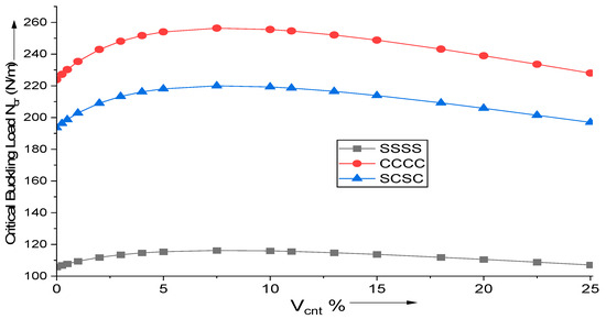
Figure 2.
Influence of MWCNT reinforcement addition on the critical buckling load for uniaxial buckling of (AS40/3501-6) laminated composite.
For various MWCNT fiber additions, the influence of changes in fiber orientation on the critical buckling load of uniaxial buckling is investigated. The plate is supported by a simple base and is moderately thick (a/h = 10). Figure 3 depicts the findings of a paramedic research conducted on a square, simply supported composite laminate with layer configuration [θ°/−θ°/θ°/−θ°]. Using the proposed HSDT-based FE (finite element) formulation, the critical buckling load given by Ncr (MN/m) is computed. Observations indicate that the magnitude of critical buckling load is greatest for (θ = 45°) cross-ply laminate.
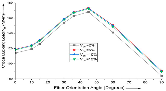
Figure 3.
Effect of variation in fiber orientation angle on the critical buckling load of uniaxial buckling of (AS40/3501-6) laminated composite.
The influence of the aspect ratio (a/h) and MWCNT addition on critical buckling load is investigated. Using the proposed HSDT-based FE formulation, the critical buckling load of uniaxial buckling, Ncr (MN/m), is calculated. As shown in Figure 4, when the thickness ratio increases, the variation of the critical buckling load decreases as after (a/h ratio > 40), there is no variation of significance. This demonstrates that the thickness of the plate significantly influences the critical buckling load of uniaxial buckling for thick plates but it is negligible for thin plates.
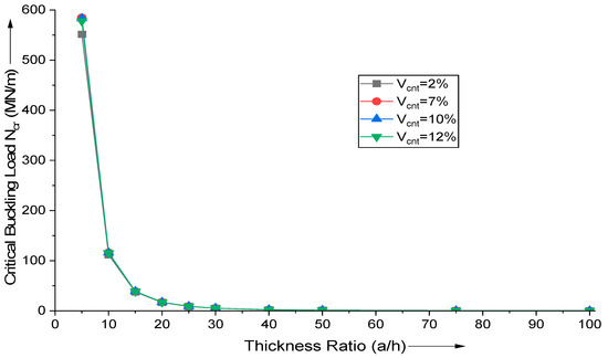
Figure 4.
Influence of variation in thickness ratio (a/h) on the critical buckling load of uniaxial buckling of (AS40/3501-6) laminated composite.
The aspect ratio (a/b) has a significant influence on the critical buckling load of uniaxial buckling. The influence of aspect ratio and MWCNT addition is explored in Figure 5. A high aspect ratio contributes to a very high critical buckling load since the decrease in smaller side increases the plate’s stiffness, thereby raising the critical buckling load. Using the proposed HSDT-based FE formulation, the critical buckling load for uniaxial buckling, Ncr (MN/m), is estimated. Figure 5 demonstrates that increasing aspect ratio (a/b) raises the critical buckling load, since the smaller dimensions control the phenomenon of buckling.
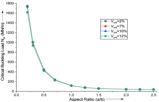
Figure 5.
Influence of variation in aspect ratio (a/b) on the critical buckling load for uniaxial buckling of (AS40/3501-6) laminated composite.
4. Conclusions
A comprehensive hybrid polynomial and hyperbolic form function-based two-dimensional mathematical model is introduced to analyze the instability of MWCNT-reinforced composite plates. The 2D finite element implementation of the current model with a nine-node isoparametric finite element is executed in proprietary MATLAB (R2019a) code. The model was evaluated to examine the impact of including MWCNT fillers into laminated composites under various external loading, thickness ratios, aspect ratios, laminate structures, and support conditions. The convergence and correctness of the finite element model were validated against available research results and comprehensive parametric investigations were carried out to create standards for future research. The following conclusions were drawn from the present research:
- The current 2D finite element model has sufficient efficiency to yield results that are closely matching with benchmark outcomes of established 3D theories. For moderately thick and thin plates, the finite element model exhibits exceptional performance.
- When MWCNT fillers are incorporated in the polymer matrix, the critical buckling load of the composite laminated significantly increases.
- MWCNT incorporation enhances the plate performance up to 8–10% by volume. Beyond that value, the composite exhibits deterioration of its elastic characteristics.
- The critical buckling stresses of the laminated structure with cross-ply orientation is increased, compared to alternative orientations of carbon fiber reinforcement within the composite.
- The optimization of the critical buckling load in the composite plate with the MWCNT inclusion being particularly beneficial for plates that are fixed on all sides.
- The augmentation of laminate layers increases the critical buckling load of the laminate. The impact of the number of layers is particularly significant in thick plates.
Author Contributions
Conceptualization, J.S. and A.K.; methodology, J.S. and D.B.-H.; software, A.K.; validation, J.S. and A.K.; formal analysis, all authors.; investigation, J.S. and W.A.; resources, J.S.; data curation, J.S., A.K., B.S.-B., W.A. and D.B.-H. All authors have read and agreed to the published version of the manuscript.
Funding
This research received no external funding.
Institutional Review Board Statement
Not applicable.
Informed Consent Statement
Not applicable.
Data Availability Statement
The original contributions presented in this study are included in the article. Further inquiries can be directed to the corresponding author.
Conflicts of Interest
The authors declare no conflicts of interest.
Appendix A
References
- Affdl, J.C.H.; Kardos, J.L. The Halpin-Tsai Equations: A Review. Polym. Eng. Sci. 1976, 16, 344–352. [Google Scholar] [CrossRef]
- Pagano, N. Exact Solutions for Rectangular Bidirectional Composites and Sandwich Plates. J. Compos. Mater. 1970, 4, 20–34. [Google Scholar] [CrossRef]
- Yang, B.; Chen, W.Q.; Ding, H.J. 3D Elasticity Solutions for Equilibrium Problems of Transversely Isotropic FGM Plates with Holes. Acta Mech. 2014, 226, 1571–1590. [Google Scholar] [CrossRef]
- Brischetto, S.; Cesare, D. 3D Electro-Elastic Static Analysis of Advanced Plates and Shells. Int. J. Mech. Sci. 2024, 280, 109620. [Google Scholar] [CrossRef]
- Karttunen, A.T.; Von Hertzen, R.; Reddy, J.; Romanoff, J. Bridging Plate Theories and Elasticity Solutions. Int. J. Solids Struct. 2016, 106, 251–263. [Google Scholar] [CrossRef]
- Robbins, D.H.; Reddy, J.N. Modelling of Thick Composites Using a Layerwise Laminate Theory. Int. J. Numer. Methods Eng. 1993, 36, 655–677. [Google Scholar] [CrossRef]
- Li, D. Layerwise Theories of Laminated Composite Structures and Their Applications: A Review. Arch. Comput. Methods Eng. 2020, 28, 577–600. [Google Scholar] [CrossRef]
- Rakočević, M.; Popović, S.; Ivanišević, N. A Computational Method for Laminated Composite Plates Based on Layerwise Theory. Compos. Part B Eng. 2017, 122, 202–218. [Google Scholar] [CrossRef]
- Goswami, S.; Becker, W. Analysis of Sandwich Plates with Compressible Core Using Layerwise Refined Plate Theory and Interface Stress Continuity. J. Compos. Mater. 2015, 50, 201–217. [Google Scholar] [CrossRef]
- Kirchhoff, G. Über das Gleichgewicht und die Bewegung einer elastischen Scheibe. J. Reine Angew. Math. 1850, 1850, 51–88. [Google Scholar] [CrossRef]
- Reissner, E. The Effect of Transverse Shear Deformation on the Bending of Elastic Plates. J. Appl. Mech. 1945, 12, A69–A77. [Google Scholar] [CrossRef]
- Mindlin, R.D. Influence of Rotatory Inertia and Shear on Flexural Motions of Isotropic, Elastic Plates. J. Appl. Mech. 1951, 18, 31–38. [Google Scholar] [CrossRef]
- Khdeir, A.A.; Reddy, J.N. Free Vibrations of Laminated Composite Plates Using Second-Order Shear Deformation Theory. Comput. Struct. 1999, 71, 617–626. [Google Scholar] [CrossRef]
- Shahrjerdi, A.; Mustapha, F.; Bayat, M.; Majid, D.L.A. Free Vibration Analysis of Solar Functionally Graded Plates with Temperature-Dependent Material Properties Using Second Order Shear Deformation Theory. J. Mech. Sci. Technol. 2011, 25, 2195–2209. [Google Scholar] [CrossRef]
- Shi, G. A New Simple Third-Order Shear Deformation Theory of Plates. Int. J. Solids Struct. 2006, 44, 4399–4417. [Google Scholar] [CrossRef]
- Aagaah, M.R.; Mahinfalah, M.; Jazar, G.N. Natural Frequencies of Laminated Composite Plates Using Third Order Shear Deformation Theory. Compos. Struct. 2004, 72, 273–279. [Google Scholar] [CrossRef]
- Ferreira, A.J.M.; Batra, R.C.; Roque, C.M.C.; Qian, L.F.; Martins, P.A.L.S. Static Analysis of Functionally Graded Plates Using Third-Order Shear Deformation Theory and a Meshless Method. Compos. Struct. 2004, 69, 449–457. [Google Scholar] [CrossRef]
- Carrera, E.; De Miguel, A.G.; Pagani, A. Hierarchical Theories of Structures Based on Legendre Polynomial Expansions with Finite Element Applications. Int. J. Mech. Sci. 2016, 120, 286–300. [Google Scholar] [CrossRef]
- Pagani, A.; De Miguel, A.G.; Petrolo, M.; Carrera, E. Analysis of Laminated Beams via Unified Formulation and Legendre Polynomial Expansions. Compos. Struct. 2016, 156, 78–92. [Google Scholar] [CrossRef]
- Verma, S.; Thakur, B.R.; Singh, B.N.; Maiti, D.K. Geometrically Nonlinear Flexural Analysis of Multilayered Composite Plate Using Polynomial and Non-Polynomial Shear Deformation Theories. Aerosp. Sci. Technol. 2021, 112, 106635. [Google Scholar] [CrossRef]
- Thai, H.-T.; Vo, T.P. A New Sinusoidal Shear Deformation Theory for Bending, Buckling, and Vibration of Functionally Graded Plates. Appl. Math. Model. 2012, 37, 3269–3281. [Google Scholar] [CrossRef]
- Ferreira, A.J.M.; Carrera, E.; Cinefra, M.; Roque, C.M.C.; Polit, O. Analysis of Laminated Shells by a Sinusoidal Shear Deformation Theory and Radial Basis Functions Collocation, Accounting for Through-the-Thickness Deformations. Compos. Part B Eng. 2011, 42, 1276–1284. [Google Scholar] [CrossRef]
- Wang, Y.; Wu, D. Free Vibration of Functionally Graded Porous Cylindrical Shell Using a Sinusoidal Shear Deformation Theory. Aerosp. Sci. Technol. 2017, 66, 83–91. [Google Scholar] [CrossRef]
- Mantari, J.L.; Bonilla, E.M.; Soares, C.G. A New Tangential-Exponential Higher Order Shear Deformation Theory for Advanced Composite Plates. Compos. Part B Eng. 2013, 60, 319–328. [Google Scholar] [CrossRef]
- Khorshidi, K.; Fallah, A. Buckling Analysis of Functionally Graded Rectangular Nano-Plate Based on Nonlocal Exponential Shear Deformation Theory. Int. J. Mech. Sci. 2016, 113, 94–104. [Google Scholar] [CrossRef]
- Meiche, N.E.; Tounsi, A.; Ziane, N.; Mechab, I.; AddaBedia, E.A. A New Hyperbolic Shear Deformation Theory for Buckling and Vibration of Functionally Graded Sandwich Plate. Int. J. Mech. Sci. 2011, 53, 237–247. [Google Scholar] [CrossRef]
- Grover, N.; Maiti, D.K.; Singh, B.N. A New Inverse Hyperbolic Shear Deformation Theory for Static and Buckling Analysis of Laminated Composite and Sandwich Plates. Compos. Struct. 2012, 95, 667–675. [Google Scholar] [CrossRef]
- Thai, H.-T.; Vo, T.P.; Bui, T.Q.; Nguyen, T.-K. A Quasi-3D Hyperbolic Shear Deformation Theory for Functionally Graded Plates. Acta Mech. 2013, 225, 951–964. [Google Scholar] [CrossRef]
- Nguyen, V.-H.; Nguyen, T.-K.; Thai, H.-T.; Vo, T.P. A New Inverse Trigonometric Shear Deformation Theory for Isotropic and Functionally Graded Sandwich Plates. Compos. Part B Eng. 2014, 66, 233–246. [Google Scholar] [CrossRef]
- Grover, N.; Singh, B.N.; Maiti, D.K. An Inverse Trigonometric Shear Deformation Theory for Supersonic Flutter Characteristics of Multilayered Composite Plates. Aerosp. Sci. Technol. 2016, 52, 41–51. [Google Scholar] [CrossRef]
- Farahmand, H.; Naseralavi, S.S.; Iranmanesh, A.; Mohammadi, M. Navier Solution for Buckling Analysis of Size-Dependent Functionally Graded Micro-Plates. Lat. Am. J. Solids Struct. 2016, 13, 3161–3173. [Google Scholar] [CrossRef][Green Version]
- Levinson, M.; Cooke, D.W. Thick Rectangular Plates—I: The generalized Navier solution. Int. J. Mech. Sci. 1983, 25, 199–205. [Google Scholar] [CrossRef]
- Mohammadi, M.; Saidi, A.R.; Jomehzadeh, E. Levy Solution for Buckling Analysis of Functionally Graded Rectangular Plates. Appl. Compos. Mater. 2009, 17, 81–93. [Google Scholar] [CrossRef]
- Thai, H.-T.; Kim, S.-E. Analytical Solution of a Two Variable Refined Plate Theory for Bending Analysis of Orthotropic Levy-Type Plates. Int. J. Mech. Sci. 2011, 54, 269–276. [Google Scholar] [CrossRef]
- Lam, K.Y.; Hung, K.C.; Chow, S.T. Vibration Analysis of Plates with Cutouts by the Modified Rayleigh-Ritz Method. Appl. Acoust. 1989, 28, 49–60. [Google Scholar] [CrossRef]
- Liew, K.M.; Wang, C.M. pb-2 Rayleigh-Ritz Method for General Plate Analysis. Eng. Struct. 1993, 15, 55–60. [Google Scholar] [CrossRef]
- Carrera, E. Historical Review of Zig-Zag Theories for Multilayered Plates and Shells. Appl. Mech. Rev. 2003, 56, 287–308. [Google Scholar] [CrossRef]
- Brischetto, S.; Carrera, E.; Demasi, L. Improved Bending Analysis of Sandwich Plates Using a Zig-Zag Function. Compos. Struct. 2008, 89, 408–415. [Google Scholar] [CrossRef]
- Liew, K.M.; Zhao, X.; Ferreira, A.J.M. A Review of Meshless Methods for Laminated and Functionally Graded Plates and Shells. Compos. Struct. 2011, 93, 2031–2041. [Google Scholar] [CrossRef]
- Belinha, J.; Araújo, A.L.; Ferreira, A.J.M.; Dinis, L.M.J.S.; Jorge, R.M.N. The Analysis of Laminated Plates Using Distinct Advanced Discretization Meshless Techniques. Compos. Struct. 2016, 143, 165–179. [Google Scholar] [CrossRef]
- Lei, Z.; Liew, K.; Yu, J. Buckling Analysis of Functionally Graded Carbon Nanotube-Reinforced Composite Plates Using the Element-Free kp-Ritz Method. Compos. Struct. 2012, 98, 160–168. [Google Scholar] [CrossRef]
- Shen, H.; Zhu, Z.H. Buckling and Postbuckling Behavior of Functionally Graded Nanotube-Reinforced Composite Plates in Thermal Environments. Comput. Mater. Contin. 2010, 18, 155–182. [Google Scholar] [CrossRef]
- Meng, X.; Gardner, L. Flexural Buckling of Normal and High Strength Steel CHS Columns. Structures 2021, 34, 4364–4375. [Google Scholar] [CrossRef]
- Lei, Z.; Zhang, L.; Liew, K. Buckling Analysis of CNT Reinforced Functionally Graded Laminated Composite Plates. Compos. Struct. 2016, 152, 62–73. [Google Scholar] [CrossRef]
- Zhang, J.; Zhang, M.; Tang, W.; Wang, W.; Wang, M. Buckling of Spherical Shells Subjected to External Pressure: A Comparison of Experimental and Theoretical Data. Thin-Walled Struct. 2016, 111, 58–64. [Google Scholar] [CrossRef]
- Srivastava, A.; Kumar, D. Post-Buckling Behaviour of Carbon-Nanotube-Reinforced Nanocomposite Plate. Sadhana 2016, 42, 129–141. [Google Scholar] [CrossRef]
- Kiani, Y.; Eslami, M.R. Thermal Buckling and Post-Buckling Response of Imperfect Temperature-Dependent Sandwich FGM Plates Resting on Elastic Foundation. Arch. Appl. Mech. 2011, 82, 891–905. [Google Scholar] [CrossRef]
- Thai, H.; Kim, S. Closed-Form Solution for Buckling Analysis of Thick Functionally Graded Plates on Elastic Foundation. Int. J. Mech. Sci. 2013, 75, 34–44. [Google Scholar] [CrossRef]
- Civalek, Ö.; Avcar, M. Free Vibration and Buckling Analyses of CNT Reinforced Laminated Non-Rectangular Plates by Discrete Singular Convolution Method. Eng. Comput. 2020, 38, 489–521. [Google Scholar] [CrossRef]
- Liu, T.; Chen, Y.; Hutchinson, J.W.; Jin, L. Buckling of Viscoelastic Spherical Shells. J. Mech. Phys. Solids 2022, 169, 105084. [Google Scholar] [CrossRef]
- Georgantzinos, S.K.; Antoniou, P.A.; Giannopoulos, G.I.; Fatsis, A.; Markolefas, S.I. Design of Laminated Composite Plates with Carbon Nanotube Inclusions against Buckling: Waviness and Agglomeration Effects. Nanomaterials 2021, 11, 2261. [Google Scholar] [CrossRef] [PubMed]
- Anish, N.; Chaubey, A.; Kumar, A.; Kwiatkowski, B.; Barnat-Hunek, D.; Widomski, M.K. Bi-Axial Buckling of Laminated Composite Plates Including Cutout and Additional Mass. Materials 2019, 12, 1750. [Google Scholar] [CrossRef] [PubMed]
- Vescovini, R.; Dozio, L. Exact Refined Buckling Solutions for Laminated Plates Under Uniaxial and Biaxial Loads. Compos. Struct. 2015, 127, 356–368. [Google Scholar] [CrossRef][Green Version]
Disclaimer/Publisher’s Note: The statements, opinions and data contained in all publications are solely those of the individual author(s) and contributor(s) and not of MDPI and/or the editor(s). MDPI and/or the editor(s) disclaim responsibility for any injury to people or property resulting from any ideas, methods, instructions or products referred to in the content. |
© 2025 by the authors. Licensee MDPI, Basel, Switzerland. This article is an open access article distributed under the terms and conditions of the Creative Commons Attribution (CC BY) license (https://creativecommons.org/licenses/by/4.0/).