
Temperature-Dependent Deformation Mechanisms in Ti65 Alloy: An In Situ Tensile Study
 , ,
, , 
Abstract
1. Introduction
2. Materials and Methods
2.1. Slip Trace Analysis Method
2.2. Calculation Method for Geometrical Compatibility Factor (GCF)
3. Results
4. Discussion
4.1. Slip Trace Analysis
4.2. Coordinated Deformation Mechanisms
4.2.1. Crystal Orientation Rotation
4.2.2. Grain Boundary Slip Transfer
4.2.3. Slip Modes and Microstructural Evolutions
4.2.4. MD Analysis of Dislocation During Tensile Simulations
5. Conclusions
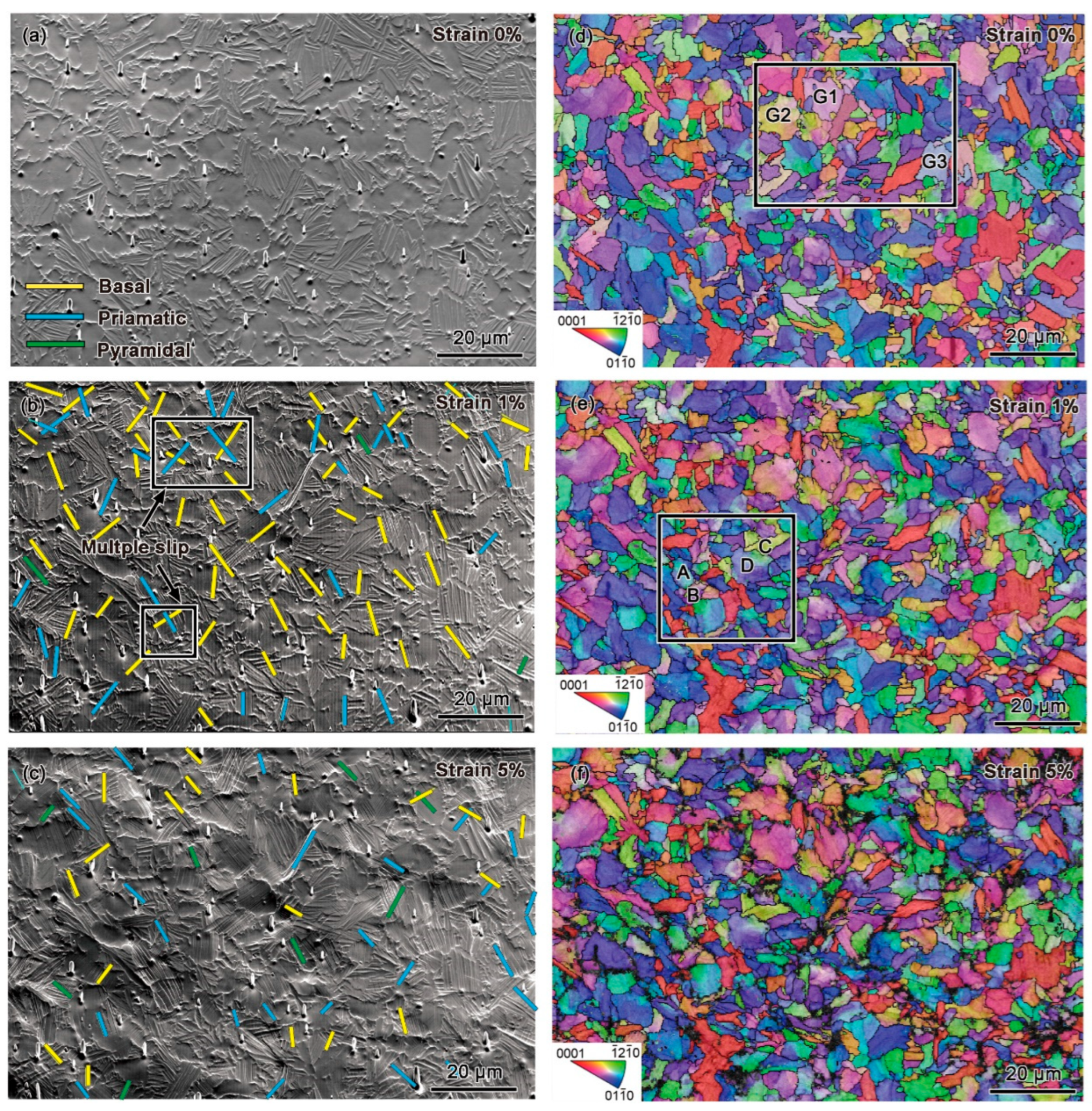
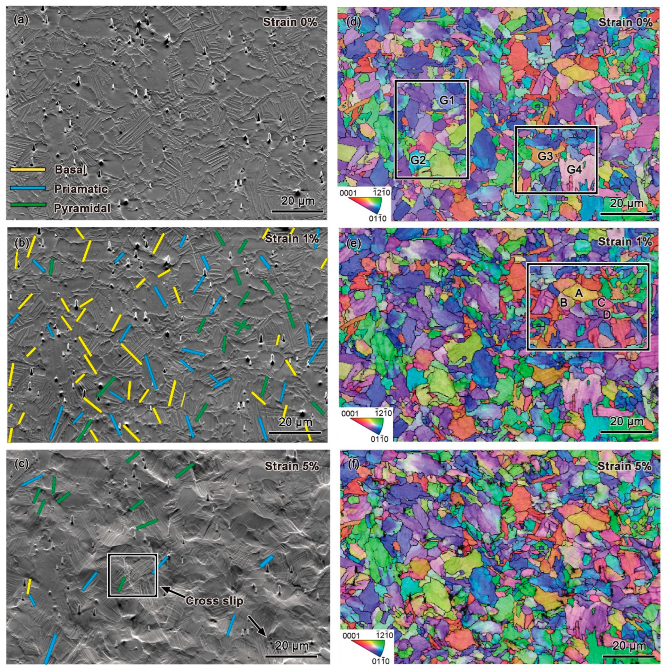
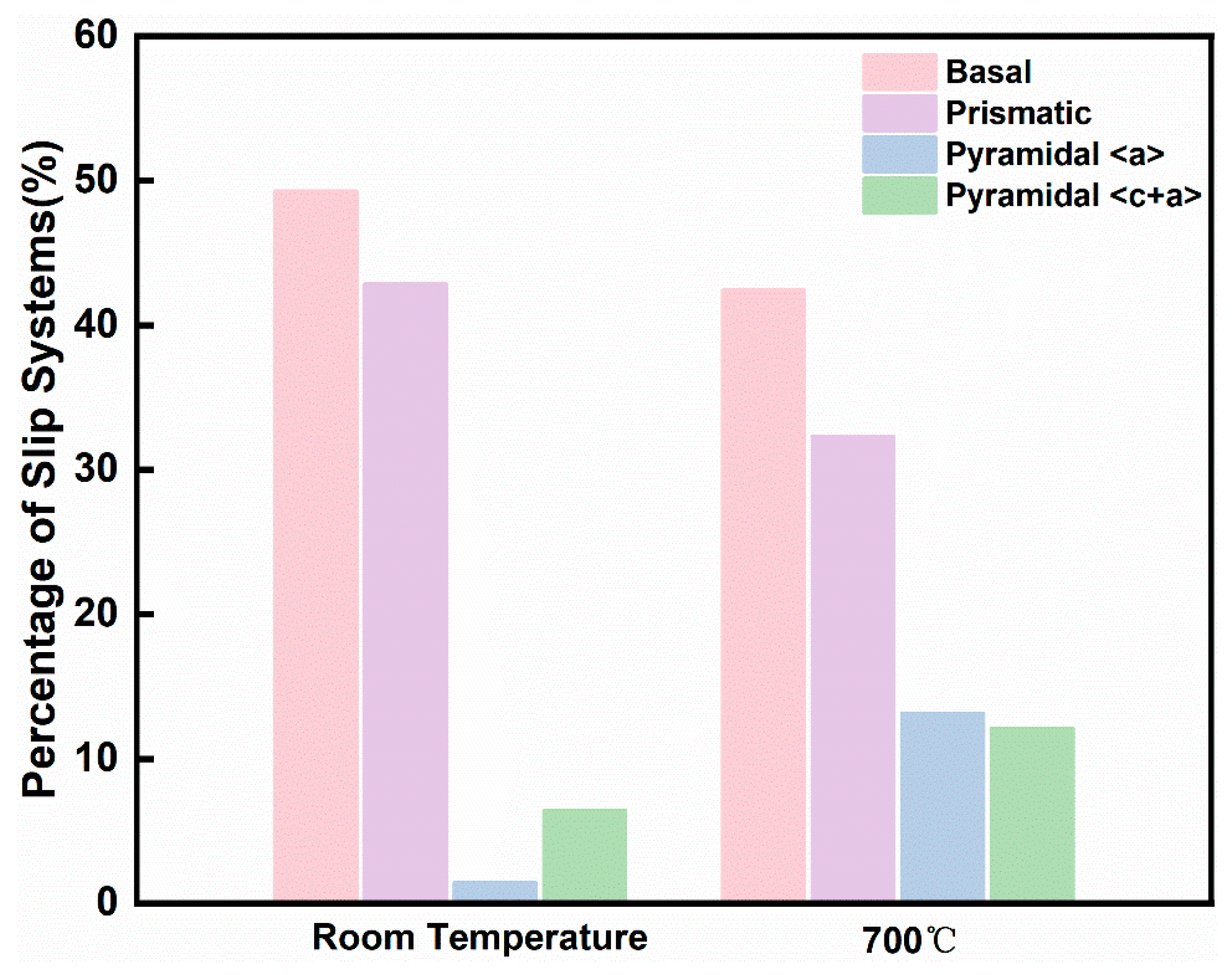
- At room temperature, deformation is dominated by basal and prismatic slip with limited pyramidal slip activation, while elevated temperatures significantly promote pyramidal <a> and <c+a> slip due to thermal activation effects, enhancing plasticity. At 5% strain, the proportion of pyramidal <c+a> slip among the statistically analyzed slip traces increased from 6.4% to 12.1%, while that of pyramidal <a> slip increased from 1.4% to 13.1%.
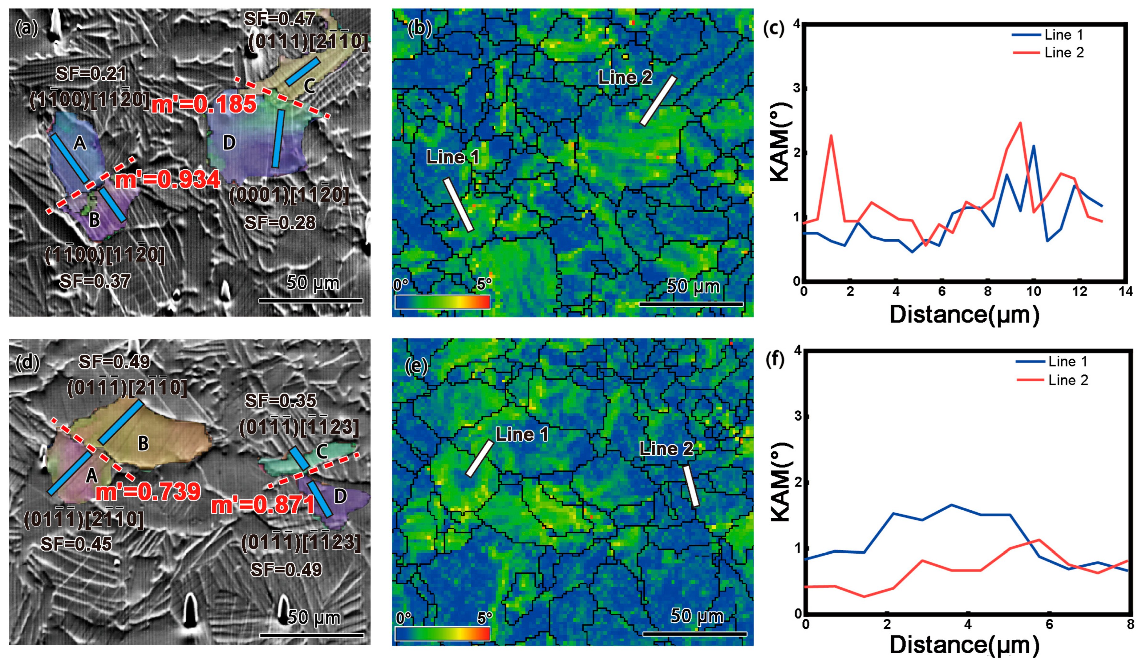
- Coordinated deformation occurs through crystal rotation and slip transfer—room-temperature deformation features multi-slip and grain rotation to accommodate strain, whereas high-temperature deformation is governed by efficient slip transfer across grain boundaries facilitated by improved geometrical compatibility. This transition in deformation mechanisms explains the alloy’s remarkable plasticity improvement at high temperatures while maintaining moderate strength.
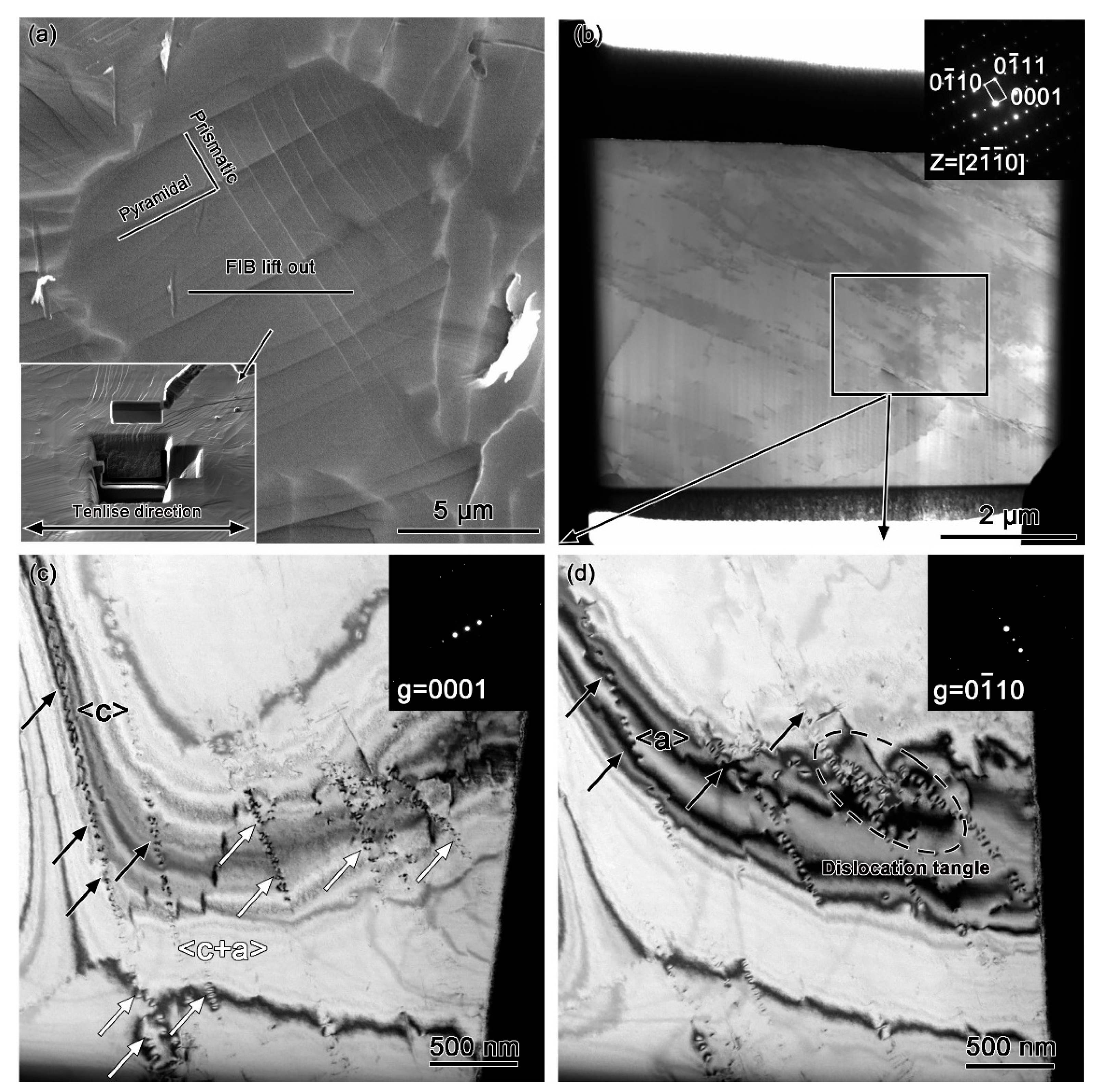
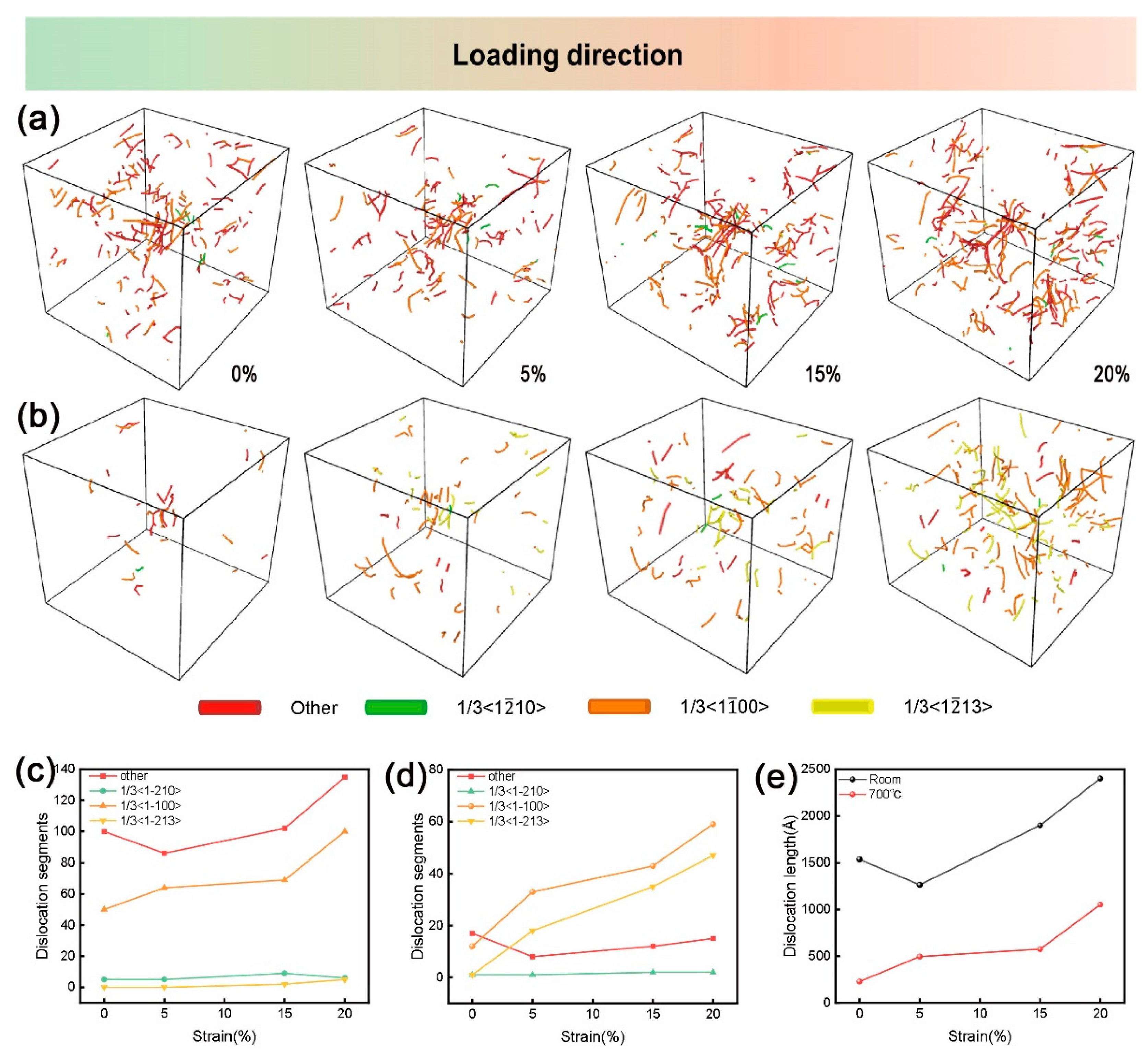
- TEM observations and molecular dynamics simulations reveal that plastic deformation is predominantly accommodated by basal and prismatic slip systems with minimal pyramidal slip contribution at room temperature. However, thermal activation at elevated temperatures reduces the critical resolved shear stress (CRSS), preferentially activating 1/3<11–23> dislocations and thereby substantially improving plastic deformation capability.
Author Contributions
Funding
Institutional Review Board Statement
Informed Consent Statement
Data Availability Statement
Conflicts of Interest
References
- Yue, K.; Liu, J.; Zhang, H.; Yu, H.; Song, Y.; Hu, Q.; Wang, Q.; Yang, R. Precipitates and alloying elements distribution in near α titanium alloy Ti65. J. Mater. Sci. Technol. 2020, 36, 91–96. [Google Scholar] [CrossRef]
- Zhao, Z.B.; Tan, H.B.; Zhang, B.H.; Liu, Y.J.; Liu, J.R.; Guo, H.M.; Zeng, W.D.; Tian, W.; Yu, Q.J. Review: Microtextures in Near α and α + β Titanium Alloys. Acta Metall. Sin. 2025, 56, 1–14. [Google Scholar]
- Zhang, H.; Zhang, C.; Liang, X.; Guo, R.; Feng, H.; Hou, Z.; Han, J.; Cheng, M.; Zhang, S.; Wang, T.; et al. Plastic slip mechanisms in high-temperature titanium alloys: Insights into silicide and Ti3Al precipitates on ductility. Scr. Mater. 2025, 256, 116412. [Google Scholar] [CrossRef]
- Wei, S.; Kim, J.; Tasan, C.C. In-situ investigation of plasticity in a Ti-Al-V-Fe (α+β) alloy: Slip mechanisms, strain localization, and partitioning. Int. J. Plast. 2022, 148, 103131. [Google Scholar] [CrossRef]
- Wei, S.; Zhu, G.; Tasan, C.C. Slip-twinning interdependent activation across phase boundaries: An in-situ investigation of a Ti-Al-V-Fe (alpha plus beta) alloy. Acta Mater. 2021, 206, 116520. [Google Scholar] [CrossRef]
- Zhao, J.; Lv, L.; Wang, K.; Liu, G. Effects of strain state and slip mode on the texture evolution of a near-α TA15 titanium alloy during hot deformation based on crystal plasticity method. J. Mater. Sci. Technol. 2020, 38, 125–134. [Google Scholar] [CrossRef]
- Semiatin, L.S.; Bieler, R.T. Effect of Texture and Slip Mode on the Anisotropy of Plastic Flow and Flow Softening during Hot Working of Ti-6Al-4V. Metall. Mater. Trans. A Phys. Metall. Mater. Sci. 2001, 32, 1787–1799. [Google Scholar] [CrossRef]
- Ma, L.; Wan, M.; Li, W.; Shao, J.; Han, X.; Zhang, J. On the superplastic deformation mechanisms of near-α TNW700 titanium alloy. J. Mater. Sci. Technol. 2022, 108, 173–185. [Google Scholar] [CrossRef]
- Meng, L.; Kitashima, T.; Lin, P.; Zheng, L.; Jiang, Z.; Zhao, J. In situ EBSD investigation of microtexture evolution and slip activation of α macrozones during tensile deformation in Ti-6Al-4V alloy. Mater. Sci. Eng. A 2025, 924, 147739. [Google Scholar] [CrossRef]
- Chen, H.; Zeng, W.; Luo, H.; Wang, B.; Jia, R.; Xu, B.; Xu, J. The texture evolution near the shear band and corresponding impact on the microvoid nucleation and crack propagation of Ti6242s alloys under high strain rates. Mater. Sci. Eng. A 2024, 915, 147243. [Google Scholar] [CrossRef]
- Huang, L.; Sun, Z.; Cao, J.; Yin, Z. The formation and evolution of macrozone in Ti-6242S alloy during thermo-mechanical processing. J. Alloys Compd. 2020, 861, 158533. [Google Scholar] [CrossRef]
- Niu, Y.; Hou, H.; Li, M.; Li, Z. High temperature deformation behavior of a near alpha Ti600 titanium alloy. Mater. Sci. Eng. A 2008, 492, 24–28. [Google Scholar] [CrossRef]
- Fan, J.K.; Kou, H.C.; Lai, M.J.; Tang, B.; Chang, H.; Li, J.S. High Temperature Deformation Behavior of Ti-7333 Titanium Alloy and its Flow Stress Model. Adv. Mater. Res. 2012, 1897, 945–950. [Google Scholar] [CrossRef]
- Zhang, W.; Lu, J.; Wang, J.; Sang, L.; Ma, J.; Zhang, Y.; Zhang, Z. In-situ EBSD study of deformation behavior of Inconel 740H alloy at high-temperature tensile loading. J. Alloys Compd. 2020, 820, 153424. [Google Scholar] [CrossRef]
- Wang, H.; Boehlert, C.; Wang, Q.; Yin, D.; Ding, W. In-situ analysis of the tensile deformation modes and anisotropy of extruded Mg-10Gd-3Y-0.5Zr (wt.%) at elevated temperatures. Int. J. Plast. 2016, 84, 255–276. [Google Scholar] [CrossRef]
- Fu, Y.; Cheng, Y.; Cui, Y.; Xin, Y.; Zeng, Y.; Liu, X.; Chen, G. Deformation mechanism of commercially pure titanium under biaxial loading at ambient and elevated temperatures. J. Mater. Sci. Technol. 2022, 126, 237–251. [Google Scholar] [CrossRef]
- Thompson, A.P.; Aktulga, H.M.; Berger, R.; Bolintineanu, D.S.; Brown, W.M.; Crozier, P.S.; In’t Veld, P.J.; Kohlmeyer, A.; Moore, S.G.; Nguyen, T.D.; et al. LAMMPS-a flexible simulation tool for particle-based materials modeling at the atomic, meso, and continuum scales. Comput. Phys. Commun. 2022, 271, 108171. [Google Scholar] [CrossRef]
- Zhang, S.; Zeng, W.; Zhao, Q.; Ge, L.; Zhang, M. In situ SEM study of tensile deformation of a near-β titanium alloy. Mater. Sci. Eng. A 2017, 708, 574–581. [Google Scholar] [CrossRef]
- Sofinowski, K.; Šmíd, M.; van Petegem, S.; Rahimi, S.; Connolley, T.; van Swygenhoven, H. In situ characterization of work hardening and springback in grade 2 α -titanium under tensile load. Acta Mater. 2019, 181, 87–98. [Google Scholar] [CrossRef]
- Huang, S.; Zhao, Q.; Lin, C.; Wu, C.; Zhao, Y.; Jia, W.; Mao, C. In-situ investigation of tensile behaviors of Ti-6Al alloy with extra low interstitial. Mater. Sci. Eng. A 2021, 809, 140958. [Google Scholar] [CrossRef]
- Lee, T.C.; Robertson, I.M.; Birnbaum, H.K. An In Situ transmission electron microscope deformation study of the slip transfer mechanisms in metals. Metall. Trans. A 1990, 21, 24, 37–47. [Google Scholar] [CrossRef]
- Joseph, S.; Bantounas, I.; Lindley, T.C.; Dye, D. Slip transfer and deformation structures resulting from the low cycle fatigue of near-alpha titanium alloy Ti-6242Si. Int. J. Plast. 2018, 100, 90–103. [Google Scholar] [CrossRef]
- Hutchinson, W.; Barnett, M. Effective values of critical resolved shear stress for slip in polycrystalline magnesium and other hcp metals. Scr. Mater. 2010, 63, 737–740. [Google Scholar] [CrossRef]
- Ren, J.; Li, L.; Wang, Q.; Xin, C.; Gao, Q.; Li, J.; Xue, H.; Lu, X.; Tang, F. Effect of environmental media on the growth rate of fatigue crack in TC4 titanium alloy: Seawater and air. Corros. Sci. 2024, 230, 111941. [Google Scholar] [CrossRef]
- Pilchak, A.; Williams, J. Crystallography of fluted fracture in near-α titanium alloys. Metall. Mater. Trans. A 2010, 41, 22–25. [Google Scholar] [CrossRef]
- He, R.; Peng, H.; Liu, F.; Khan, M.K.; Chen, Y.; He, C.; Wang, C.; Wang, Q.; Liu, Y. Crack Initiation Mechanism and Life Prediction of Ti60 Titanium Alloy Considering Stress Ratios Effect in Very High Cycle Fatigue Regime. Materials 2022, 15, 2800. [Google Scholar] [CrossRef]
- Magazzù, A.; Marcuello, C. Investigation of Soft Matter Nanomechanics by Atomic Force Microscopy and Optical Tweezers: A Comprehensive Review. Nanomaterials 2023, 13, 963. [Google Scholar] [CrossRef]
- Lin, P.; Feng, A.; Yuan, S.; Li, G.; Shen, J. Microstructure and texture evolution of a near-α titanium alloy during hot deformation. Mater. Sci. Eng. A 2013, 563, 16–20. [Google Scholar] [CrossRef]
- Wan, V.; Cuddihy, M.; Jiang, J.; MacLachlan, D.; Dunne, F. An HR-EBSD and computational crystal plasticity investigation of microstructural stress distributions and fatigue hotspots in polycrystalline copper. Acta Mater. 2016, 115, 45–57. [Google Scholar] [CrossRef]
- Naka, S.; Lasalmonie, A. Cross-slip on the first order pyramidal plane (10-11) of a-type dislocations [1-210] in the plastic deformation of α-titanium single crystals. J. Mater. Sci. 1983, 18, 2613–2617. [Google Scholar] [CrossRef]
- Li, H.; Mason, D.; Bieler, T.; Boehlert, C.; Crimp, M. Methodology for estimating the critical resolved shear stress ratios of α-phase Ti using EBSD-based trace analysis. Acta Mater. 2013, 61, 7555–7567. [Google Scholar] [CrossRef]
- Jia, R.; Zeng, W.; Zhao, Z.; Zhang, P.; Xu, J.; Wang, Q. In-situ investigation on the deformation mechanism of duplex microstructure of a near α titanium alloy. J. Alloys Compd. 2022, 893, 162184. [Google Scholar] [CrossRef]
- Mittemeijer, E. Fundamentals of Materials Science; Springer: Berlin/Heidelberg, Germany, 2010. [Google Scholar]
- Liu, Y.; Zhao, Z.; Wang, Q.; Yang, J.; Liu, Y.; Liu, J.; Yang, R. An Orientation Relationship Between Parent Grains and Its Application to Variant Selection of Transformed α in Titanium Alloys. Metall. Mater. Trans. A 2025, 56, 801–814. [Google Scholar] [CrossRef]
- He, D.; Zhu, J.; Zaefferer, S.; Raabe, D. Effect of retained beta layer on slip transmission in Ti–6Al–2Zr–1Mo–1V near alpha titanium alloy during tensile deformation at room temperature. Mater. Des. 2013, 56, 937–942. [Google Scholar] [CrossRef]
- Li, Y.; Gao, P.; Yu, J.; Jin, S.; Chen, S.; Zhan, M. Mesoscale deformation mechanisms in relation with slip and grain boundary sliding in TA15 titanium alloy during tensile deformation. J. Mater. Sci. Technol. 2022, 98, 72–86. [Google Scholar] [CrossRef]
- Huangfu, B.; Liu, Y.; Liu, X.; Wu, X.; Bai, H. Anisotropy of Additively Manufactured Metallic Materials. Materials 2024, 17, 3653. [Google Scholar] [CrossRef]


Disclaimer/Publisher’s Note: The statements, opinions and data contained in all publications are solely those of the individual author(s) and contributor(s) and not of MDPI and/or the editor(s). MDPI and/or the editor(s) disclaim responsibility for any injury to people or property resulting from any ideas, methods, instructions or products referred to in the content. |
© 2025 by the authors. Licensee MDPI, Basel, Switzerland. This article is an open access article distributed under the terms and conditions of the Creative Commons Attribution (CC BY) license (https://creativecommons.org/licenses/by/4.0/).
Share and Cite
Li, H.; Li, C.; Chen, D.; Liu, Y.; Zhao, Z.; Zhang, B.; Qi, M.; Liu, J.; Wang, Q. Temperature-Dependent Deformation Mechanisms in Ti65 Alloy: An In Situ Tensile Study. Materials 2025, 18, 3270. https://doi.org/10.3390/ma18143270
Li H, Li C, Chen D, Liu Y, Zhao Z, Zhang B, Qi M, Liu J, Wang Q. Temperature-Dependent Deformation Mechanisms in Ti65 Alloy: An In Situ Tensile Study. Materials. 2025; 18(14):3270. https://doi.org/10.3390/ma18143270
Chicago/Turabian StyleLi, Haitao, Chenxu Li, Dongmei Chen, Yujing Liu, Zibo Zhao, Bohua Zhang, Meng Qi, Jianrong Liu, and Qingjiang Wang. 2025. "Temperature-Dependent Deformation Mechanisms in Ti65 Alloy: An In Situ Tensile Study" Materials 18, no. 14: 3270. https://doi.org/10.3390/ma18143270
APA StyleLi, H., Li, C., Chen, D., Liu, Y., Zhao, Z., Zhang, B., Qi, M., Liu, J., & Wang, Q. (2025). Temperature-Dependent Deformation Mechanisms in Ti65 Alloy: An In Situ Tensile Study. Materials, 18(14), 3270. https://doi.org/10.3390/ma18143270