
Additive Manufacturing of Metals Using the MEX Method: Process Characteristics and Performance Properties—A Review


Abstract
1. Introduction
2. Characterization of the Printing Process and Applied Materials
2.1. Materials
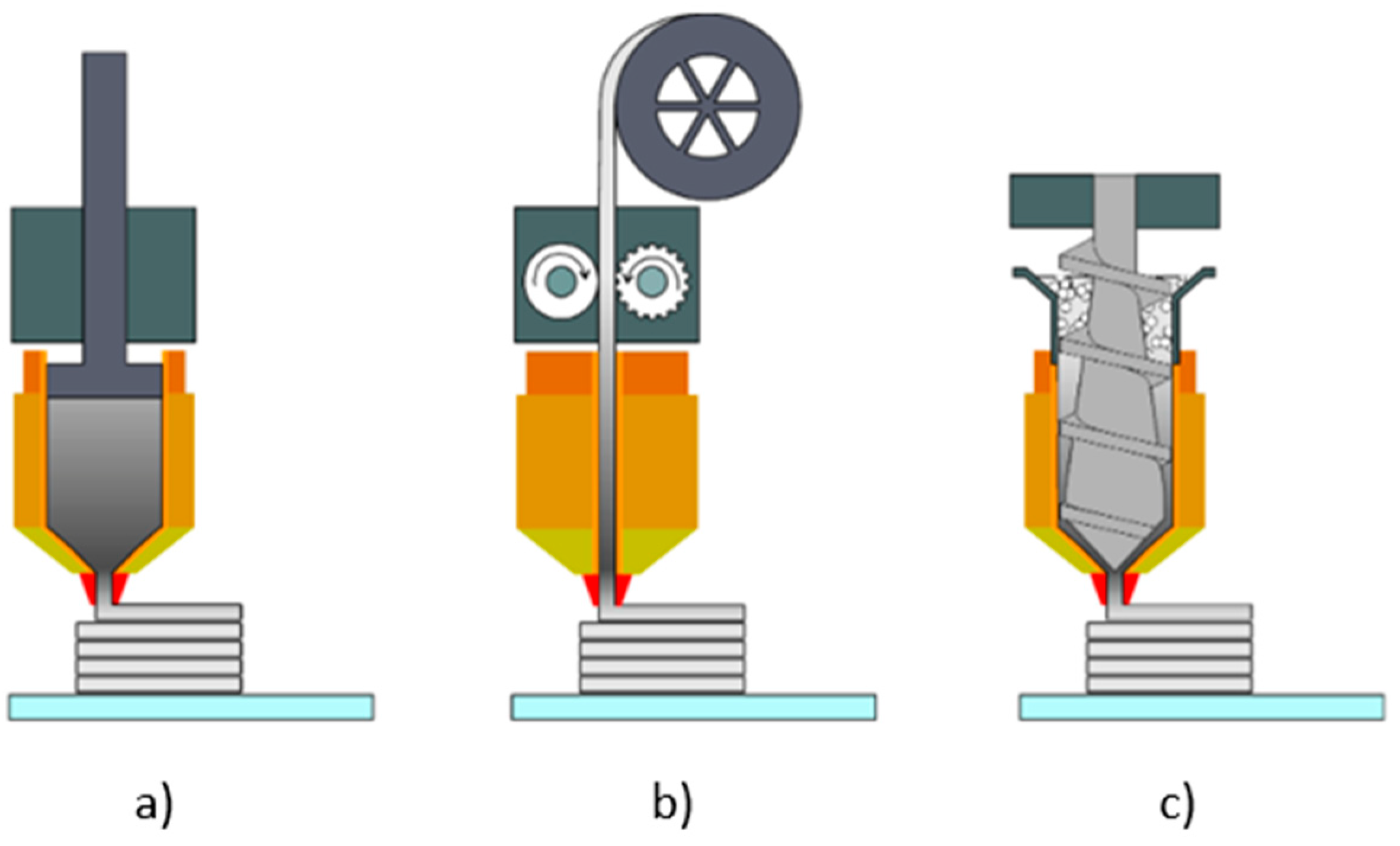
2.2. Manufacturing Process—GP
2.3. Debinding—BP
2.4. Sintering—Fully Metal Parts
2.5. Functional Properties of MEXM
3. Comparison of Metal Parts Manufactures by MEXM with Other Techniques
4. Effect of Process Parameters on Functional Characteristics
4.1. Infill Density and Pattern
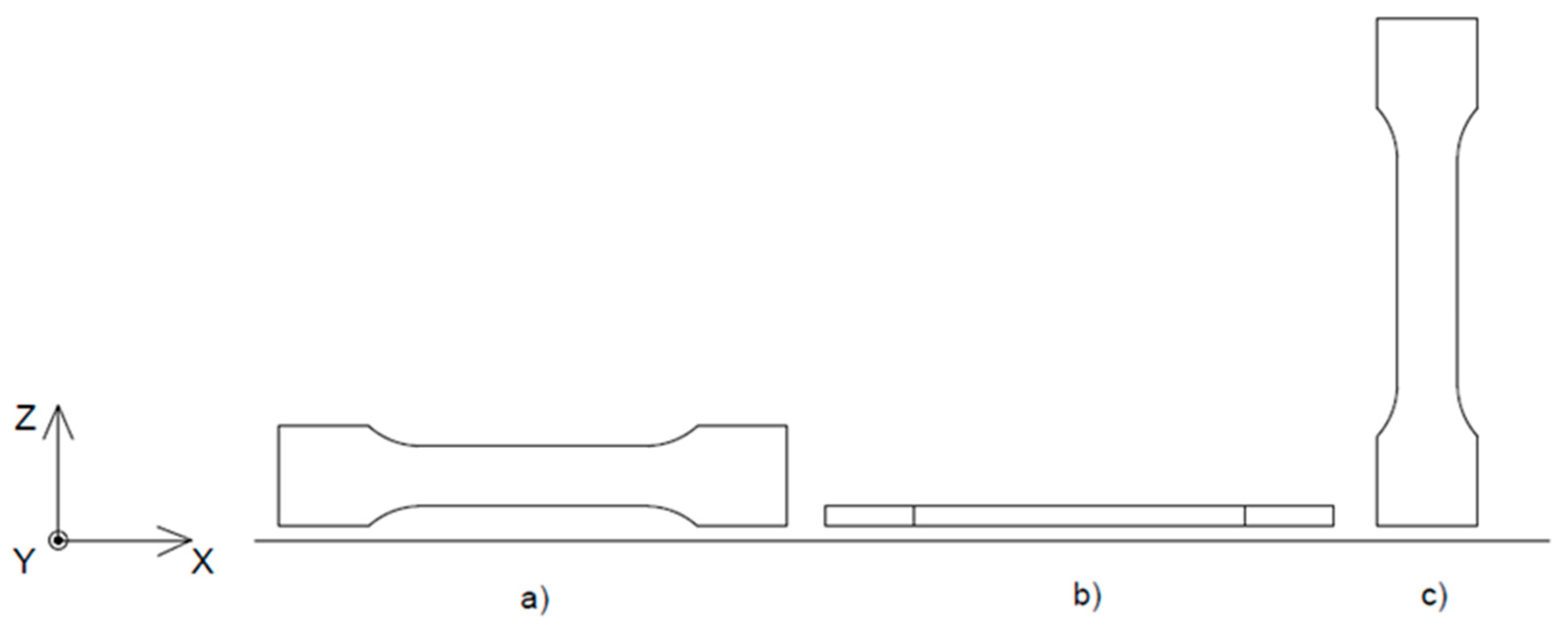
4.2. Orientation of Printed Samples
5. Pre-Processing and Post-Processing
- Surface Mechanical Attrition Treatment (SMAT)—Proven to reduce residual stress and densify the surface layer by severe plastic deformation, SMAT can lower near-surface porosity and improve fatigue performance [154].
- Hot Isostatic Pressing (HIP)—While expensive and time-consuming, HIP has shown significant effectiveness in eliminating internal pores, particularly for high-performance applications (e.g., aerospace, medical). Selective use of HIP, post-sintering, can raise density from ~95% to >99% [165,166,167,168,169].
- Post-sintering thermal aging (e.g., H900 for 17-4PH)—This can induce phase transformation and close micropores while increasing hardness. Pellegrini et al. [164] report up to 34% reduction in porosity and 18.9% gain in hardness.
- Controlled part compression during green part heating—As shown in [160], light pressing of green parts prior to sintering helps remove minor voids and improves layer cohesion.
6. Summary and Challenges
Author Contributions
Funding
Institutional Review Board Statement
Informed Consent Statement
Data Availability Statement
Conflicts of Interest
References
- Pantermehl, S.; Emmert, S.; Foth, A.; Grabow, N.; Alkildani, S.; Bader, R.; Barbeck, M.; Jung, O. 3D Printing for Soft Tissue Regeneration and Applications in Medicine. Biomedicines 2021, 9, 336. [Google Scholar] [CrossRef] [PubMed]
- ISO 17296-2:2015; Additive Manufacturing—General Principles—Part 2: Overview of Process Categories and Feedstock. ISO: Geneva, Switzerland, 2015.
- Zhang, C.; Li, X.; Jiang, L.; Tang, D.; Xu, H.; Zhao, P.; Fu, J.; Zhou, Q.; Chen, Y. 3D Printing of Functional Magnetic Materials: From Design to Applications. Adv. Funct. Mater. 2021, 31, 1–38. [Google Scholar] [CrossRef]
- Mazeeva, A.; Masaylo, D.; Razumov, N.; Konov, G.; Popovich, A. 3D Printing Technologies for Fabrication of Magnetic Materials Based on Metal—Polymer Composites: A Review. Materials 2023, 16, 6928. [Google Scholar] [CrossRef]
- Kluczyński, J.; Śnieżek, L.; Kravcov, A.; Grzelak, K.; Svoboda, P.; Szachogłuchowicz, I.; Franek, O.; Morozov, N.; Torzewski, J.; Kubeček, P. The examination of restrained joints created in the process of multi-material FFF additive manufacturing technology. Materials 2020, 13, 903. [Google Scholar] [CrossRef]
- Yang, Y.; Song, X.; Li, X.; Chen, Z.; Zhou, C.; Zhou, Q.; Chen, Y. Recent Progress in Biomimetic Additive Manufacturing Technology: From Materials to Functional Structures. Adv. Mater. 2018, 30, 1–34. [Google Scholar] [CrossRef]
- Terry, S.; Fidan, I.; Tantawi, K. Preliminary Investigation into Metal-Material Extrusion. Prog. Addit. Manuf. 2021, 6, 133–141. [Google Scholar] [CrossRef]
- Jasik, K.; Kluczyński, J.; Miedzińska, D.; Popławski, A.; Łuszczek, J.; Zygmuntowicz, J.; Piotrkiewicz, P.; Perkowski, K.; Wachowski, M.; Grzelak, K. Comparison of Additively Manufactured Polymer-Ceramic Parts Obtained via Different Technologies. Materials 2024, 17, 240. [Google Scholar] [CrossRef]
- Mousapour, M.; Salmi, M.; Klemettinen, L.; Partanen, J. Feasibility Study of Producing Multi-Metal Parts by Fused Filament Fabrication (FFF) Technique. J. Manuf. Process. 2021, 67, 438–446. [Google Scholar] [CrossRef]
- Santamaria, R.; Salasi, M.; Bakhtiari, S.; Leadbeater, G.; Iannuzzi, M.; Quadir, M.Z. Microstructure and Mechanical Behaviour of 316L Stainless Steel Produced Using Sinter-Based Extrusion Additive Manufacturing. J. Mater. Sci. 2022, 57, 9646–9662. [Google Scholar] [CrossRef]
- Ciccullo, F.; Fabbri, M.; Abdelkafi, N.; Pero, M. Exploring the potential of business models for sustainability and big data for food waste reduction. J. Clean. Prod. 2022, 340, 130673. [Google Scholar] [CrossRef]
- Rajendran, S.; Palani, G.; Kanakaraj, A.; Shanmugam, V.; Veerasimman, A.; Gądek, S.; Korniejenko, K.; Marimuthu, U. Metal and Polymer Based Composites Manufactured Using Additive Manufacturing—A Brief Review. Polymers 2023, 15, 2564. [Google Scholar] [CrossRef] [PubMed]
- Prasetyo, A.; Noviana, N.; Rosdiana, W.; Anwar, M.A.; Harwijayanti, B.P.; Fahlevi, M. Stunting Convergence Management Framework through System Integration Based on Regional Service Governance. Sustainability 2023, 15, 1821. [Google Scholar] [CrossRef]
- Bourell, D.L. Perspectives on Additive Manufacturing. Annu. Rev. Mater. Res. 2016, 46, 1–18. [Google Scholar] [CrossRef]
- Wohlers Associates. Executive Summary of the Wohlers Report 2015; Wohlers Associates: Fort Collins, CO, USA, 2014; p. 10. [Google Scholar]
- Goffard, R.; Sforza, T.; Clarinval, A.; Dormal, T.; Boilet, L.; Hocquet, S.; Cambier, F. Additive Manufacturing of Biocompatible Ceramics. Adv. Prod. Eng. Manag. 2013, 8, 96–106. [Google Scholar] [CrossRef]
- Murr, L.E.; Gaytan, S.M.; Medina, F.; Lopez, H.; Martinez, E.; MacHado, B.I.; Hernandez, D.H.; Martinez, L.; Lopez, M.I.; Wicker, R.B.; et al. Next-Generation Biomedical Implants Using Additive Manufacturing of Complex Cellular and Functional Mesh Arrays. Philos. Trans. R. Soc. A Math. Phys. Eng. Sci. 2010, 368, 1999–2032. [Google Scholar] [CrossRef]
- Buchanan, C.; Gardner, L. Metal 3D Printing in Construction: A Review of Methods, Research, Applications, Opportunities and Challenges. Eng. Struct. 2019, 180, 332–348. [Google Scholar] [CrossRef]
- Frazier, W.E. Metal Additive Manufacturing: A Review. J. Mater. Eng. Perform. 2014, 23, 1917–1928. [Google Scholar] [CrossRef]
- Monostori, L.; Majstorovic, V.D.; Hu, S.J.; Djurdjanovic, D. Lecture Notes in Mechanical Engineering, Proceedings of the 4th International Conference on the Industry 4.0 Model for Advanced Manufacturing: AMP 2019, Belgrade, Serbia, 3–6 June 2019; Springer: Berlin/Heidelberg, Germany, 2019; ISBN 9783030181796. [Google Scholar]
- Mazurkiewicz, M.; Kluczyński, J.; Jasik, K.; Sarzyński, B.; Szachogłuchowicz, I.; Łuszczek, J.; Torzewski, J.; Śnieżek, L.; Grzelak, K.; Małek, M. Bending Strength of Polyamide-Based Composites Obtained during the Fused Filament Fabrication (FFF) Process. Materials 2022, 15, 5079. [Google Scholar] [CrossRef]
- Acierno, D.; Patti, A. Fused Deposition Modelling (FDM) of Thermoplastic-Based Filaments: Process and Rheological Properties—An Overview. Materials 2023, 16, 7664. [Google Scholar] [CrossRef]
- Hozdić, E.; Hozdić, E. Comparative Analysis of the Influence of Mineral Engine Oil on the Mechanical Parameters of FDM 3D-Printed PLA, PLA+CF, PETG, and PETG+CF Materials. Materials 2023, 16, 6342. [Google Scholar] [CrossRef]
- Xiao, Y.; Zhang, S.; Chen, J.; Guo, B.; Chen, D. Mechanical Performance of 3D-Printed Polyethylene Fibers and Their Durability against Degradation. Materials 2023, 16, 5182. [Google Scholar] [CrossRef] [PubMed]
- Brancewicz-Steinmetz, E.; Sawicki, J.; Byczkowska, P. The Influence of 3d Printing Parameters on Adhesion between Polylactic Acid (Pla) and Thermoplastic Polyurethane (Tpu). Materials 2021, 14, 6464. [Google Scholar] [CrossRef] [PubMed]
- Zadpoor, A.A. Frontiers of Additively Manufactured Metallic Materials. Materials 2018, 11, 1566. [Google Scholar] [CrossRef]
- Dubinin, O.N.; Bondareva, J.V.; Kuzminova, Y.O.; Simonov, A.P.; Varfolomeev, I.A.; Yakimchuk, I.V.; Evlashin, S.A. A Promising Approach to 3D Printing of Metal Foam with Defined Porosity. J. Porous Mater. 2023, 30, 1565–1573. [Google Scholar] [CrossRef]
- Ansell, T.Y. Current Status of Liquid Metal Printing. J. Manuf. Mater. Process. 2021, 5, 31. [Google Scholar] [CrossRef]
- Peng, J. Small Specimen Technology for Revealing Mechanical Properties of Alloys, 3D-Printing Metals and Welding Joints. Materials 2023, 16, 6648. [Google Scholar] [CrossRef]
- Ali, F.; Al Rashid, A.; Kalva, S.N.; Koç, M. Mg-Doped PLA Composite as a Potential Material for Tissue Engineering—Synthesis, Characterization, and Additive Manufacturing. Materials 2023, 16, 6506. [Google Scholar] [CrossRef]
- Martinelli, A.; Nitti, A.; Po, R.; Pasini, D. 3D Printing of Layered Structures of Metal-Ionic Polymers: Recent Progress, Challenges and Opportunities. Materials 2023, 16, 5327. [Google Scholar] [CrossRef]
- Sawczuk, P.; Kluczyński, J.; Sarzyński, B.; Szachogłuchowicz, I.; Jasik, K.; Łuszczek, J.; Grzelak, K.; Płatek, P.; Torzewski, J.; Małek, M. Regeneration of the Damaged Parts with the Use of Metal Additive Manufacturing—Case Study. Materials 2023, 16, 3772. [Google Scholar] [CrossRef]
- Gupta, M. Special Issue: 3D Printing of Metals. Appl. Sci. 2019, 9, 2563. [Google Scholar] [CrossRef]
- Agyapong, J.; Czekanski, A.; Boakye-Yiadom, S. Effect of Heat Treatment on Microstructural Evolution and Properties of Cemented Carbides (WC-17Co) Reinforced with 3% Volume Hexagonal-Boron Nitride (h-BN) and Processed by Selective Laser Sintering (SLS). Mater. Charact. 2021, 174, 110968. [Google Scholar] [CrossRef]
- Kromanis, A.; Vevers, A. Technological Assurance of Ti-6Al-4V Parts Produced by Additive Manufacturing Using Selective Metal Laser Sintering. Latv. J. Phys. Tech. Sci. 2022, 59, 170–179. [Google Scholar] [CrossRef]
- Maszybrocka, J.; Stwora, A.; Gapiński, B.; Skrabalak, G.; Karolus, M. Morphology and Surface Topography of Ti6Al4V Lattice Structure Fabricated by Selective Laser Sintering. Bull. Polish Acad. Sci. Tech. Sci. 2017, 65, 85–92. [Google Scholar] [CrossRef]
- Santos, L.S.; Gupta, S.K.; Bruck, H.A. Simulation of Buckling of Internal Features during Selective Laser Sintering of Metals. Addit. Manuf. 2018, 23, 235–245. [Google Scholar] [CrossRef]
- Dalaee, M.; Cheaitani, F.; Arabi-Hashemi, A.; Rohrer, C.; Weisse, B.; Leinenbach, C.; Wegener, K. Feasibility Study in Combined Direct Metal Deposition (DMD) and Plasma Transfer Arc Welding (PTA) Additive Manufacturing. Int. J. Adv. Manuf. Technol. 2020, 106, 4375–4389. [Google Scholar] [CrossRef]
- Zhao, K.; Yang, K.; Chen, M.; Wang, Z.; Wu, E.; Sun, G. Optimization of Process Parameters for Gas-Powder Behavior in the Coaxial Nozzle during Laser Direct Metal Deposition Based on Numerical Simulation. Int. J. Adv. Manuf. Technol. 2023, 130, 3967–3982. [Google Scholar] [CrossRef]
- Choi, G.S.; Bae, E.J.; Ju, B.K.; Park, Y.W. Enhancing Light Extraction Efficiency in OLED Using Scattering Structure-Embedded DMD-Based Transparent Composite Electrodes. Nanomaterials 2023, 13, 2253. [Google Scholar] [CrossRef]
- Ugla, A.A.; Kamil, D.J.; Ibrahim, Z.A.; Khudair, H.J. Improvement Characteristics of the Shaped Metal Deposited Component Using External Excited System. J. Crit. Rev. 2020, 7, 2870–2880. [Google Scholar] [CrossRef]
- Kalaš, D.; Soukup, R.; Řeboun, J.; Radouchová, M.; Rous, P.; Hamáček, A. Novel SMD Component and Module Interconnection and Encapsulation Technique for Textile Substrates Using 3D Printed Polymer Materials. Polymers 2023, 15, 2526. [Google Scholar] [CrossRef]
- Kozak, J.; Zakrzewski, T.; Witt, M.; Dębowska-Wąsak, M. Thermal Operating Window in Selective Laser Melting Processes. Trans. Aerosp. Res. 2023, 2023, 18–32. [Google Scholar] [CrossRef]
- Nitta, I.; Takahashi, R.; Tsukiyama, Y. Mechanical Behaviour of Porous Metals Fabricated by Low-Power Selective Laser Melting. J. Adv. Mech. Des. Syst. Manuf. 2022, 16, 1–18. [Google Scholar] [CrossRef]
- Chaudhry, S.; Chuitcheu, J.W.T.; Tchouambe, I.V.; Soulaïmani, A.; Das, R. Computational Modelling of SLM Additive Manufacturing of Metals. Int. J. Manuf. Res. 2022, 17, 389–421. [Google Scholar] [CrossRef]
- Szachogłuchowicz, I.; Fikus, B.; Grzelak, K.; Kluczyński, J.; Torzewski, J.; Łuszczek, J. Selective Laser Melted M300 Maraging Steel—Material Behaviour during Ballistic Testing. Materials 2021, 14, 2681. [Google Scholar] [CrossRef]
- Javaid, M.; Haleem, A. Additive Manufacturing Applications in Medical Cases: A Literature Based Review. Alexandria J. Med. 2018, 54, 411–422. [Google Scholar] [CrossRef]
- Rosli, N.A.; Alkahari, M.R.; Ramli, F.R.; Maidin, S.; Sudin, M.N.; Subramoniam, S.; Furumoto, T. Design and Development of a Low-Cost 3d Metal Printer. J. Mech. Eng. Res. Dev. 2018, 41, 47–54. [Google Scholar] [CrossRef]
- Michi, R.A.; Plotkowski, A.; Shyam, A.; Dehoff, R.R.; Babu, S.S. Towards High-Temperature Applications of Aluminium Alloys Enabled by Additive Manufacturing. Int. Mater. Rev. 2022, 67, 298–345. [Google Scholar] [CrossRef]
- Glerum, J.A.; Kenel, C.; Sun, T.; Dunand, D.C. Synthesis of Precipitation-Strengthened Al-Sc, Al-Zr and Al-Sc-Zr Alloys via Selective Laser Melting of Elemental Powder Blends. Addit. Manuf. 2020, 36, 101461. [Google Scholar] [CrossRef]
- Pérez-Ruiz, J.D.; Marin, F.; Martínez, S.; Lamikiz, A.; Urbikain, G.; López de Lacalle, L.N. Stiffening Near-Net-Shape Functional Parts of Inconel 718 LPBF Considering Material Anisotropy and Subsequent Machining Issues. Mech. Syst. Signal Process. 2022, 168, 1–18. [Google Scholar] [CrossRef]
- Pleass, C.; Jothi, S. Influence of Powder Characteristics and Additive Manufacturing Process Parameters on the Microstructure and Mechanical Behaviour of Inconel 625 Fabricated by Selective Laser Melting. Addit. Manuf. 2018, 24, 419–431. [Google Scholar] [CrossRef]
- Barba, D.; Alabort, C.; Tang, Y.T.; Viscasillas, M.J.; Reed, R.C.; Alabort, E. On the Size and Orientation Effect in Additive Manufactured Ti-6Al-4V. Mater. Des. 2020, 186, 108235. [Google Scholar] [CrossRef]
- Song, B.; Kenel, C.; Dunand, D.C. 3D Ink-Extrusion Printing and Sintering of Ti, Ti-TiB and Ti-TiC Microlattices. Addit. Manuf. 2020, 35, 101412. [Google Scholar] [CrossRef]
- Riecker, S.; Clouse, J.; Studnitzky, T.; Andersen, O.; Kieback, B. Fused Deposition Modeling-Opportunities for Cheap Metal AM. In Proceedings of the European Congress and Exhibition on Powder Metallurgy, Hamburg, Germany, 9–13 October 2016. [Google Scholar]
- Singh, P.; Shaikh, Q.; Balla, V.K.; Atre, S.V.; Kate, K.H. Estimating Powder-Polymer Material Properties Used in Design for Metal Fused Filament Fabrication (DfMF3). Jom 2020, 72, 485–495. [Google Scholar] [CrossRef]
- Concli, F.; Bonaiti, L.; Gerosa, R.; Cortese, L.; Nalli, F.; Rosa, F.; Gorla, C. Bending Fatigue Behavior of 17-4 Ph Gears Produced by Additive Manufacturing. Appl. Sci. 2021, 11, 3019. [Google Scholar] [CrossRef]
- Samykano, M.; Selvamani, S.K.; Kadirgama, K.; Ngui, W.K.; Kanagaraj, G.; Sudhakar, K. Mechanical Property of FDM Printed ABS: Influence of Printing Parameters. Int. J. Adv. Manuf. Technol. 2019, 102, 2779–2796. [Google Scholar] [CrossRef]
- Wickramasinghe, S.; Do, T.; Tran, P. FDM-Based 3D Printing of Polymer and Associated Composite: A Review on Mechanical Properties, Defects and Treatments. Polymers 2020, 12, 1529. [Google Scholar] [CrossRef]
- Shaikh, M.Q.; Lavertu, P.Y.; Kate, K.H.; Atre, S.V. Process Sensitivity and Significant Parameters Investigation in Metal Fused Filament Fabrication of Ti-6Al-4V. J. Mater. Eng. Perform. 2021, 30, 5118–5134. [Google Scholar] [CrossRef]
- Ngo, T.D.; Kashani, A.; Imbalzano, G.; Nguyen, K.T.Q.; Hui, D. Additive Manufacturing (3D Printing): A Review of Materials, Methods, Applications and Challenges. Compos. Part B Eng. 2018, 143, 172–196. [Google Scholar] [CrossRef]
- Liu, Z.; Lei, Q.; Xing, S. Mechanical Characteristics of Wood, Ceramic, Metal and Carbon Fiber-Based PLA Composites Fabricated by FDM. J. Mater. Res. Technol. 2019, 8, 3743–3753. [Google Scholar] [CrossRef]
- Ning, F.; Cong, W.; Qiu, J.; Wei, J.; Wang, S. Additive Manufacturing of Carbon Fiber Reinforced Thermoplastic Composites Using Fused Deposition Modeling. Compos. Part B Eng. 2015, 80, 369–378. [Google Scholar] [CrossRef]
- Brünler, R.; Aibibu, D.; Wöltje, M.; Anthofer, A.M.; Cherif, C. In Silico Modeling of Structural and Porosity Properties of Additive Manufactured Implants for Regenerative Medicine. Mater. Sci. Eng. C 2017, 76, 810–817. [Google Scholar] [CrossRef]
- Nurhudan, A.I.; Supriadi, S.; Whulanza, Y.; Saragih, A.S. Additive Manufacturing of Metallic Based on Extrusion Process: A Review. J. Manuf. Process. 2021, 66, 228–237. [Google Scholar] [CrossRef]
- Diani, J.; Gall, K. Finite Strain 3D Thermoviscoelastic Constitutive Model. Society 2006, 46, 486–492. [Google Scholar] [CrossRef]
- Shahrubudin, N.; Lee, T.C.; Ramlan, R. An Overview on 3D Printing Technology: Technological, Materials, and Applications. Procedia Manuf. 2019, 35, 1286–1296. [Google Scholar] [CrossRef]
- Thompson, Y.; Gonzalez-Gutierrez, J.; Kukla, C.; Felfer, P. Fused Filament Fabrication, Debinding and Sintering as a Low Cost Additive Manufacturing Method of 316L Stainless Steel. Addit. Manuf. 2019, 30, 100861. [Google Scholar] [CrossRef]
- Singh, P.; Balla, V.K.; Tofangchi, A.; Atre, S.V.; Kate, K.H. Printability Studies of Ti-6Al-4V by Metal Fused Filament Fabrication (MF3). Int. J. Refract. Met. Hard Mater. 2020, 92, 105249. [Google Scholar] [CrossRef]
- Available online: https://get3d.pl/wp-content/uploads/2021/03/Ultrafuse_17-4PH_TDS_EN_v2.0.pdf?_gl=1*ciao0m*_up*MQ..*_ga*MTYzMzM4Mjc3MS4xNzQ4MDA1ODg3*_ga_8PFJM0XGSM*czE3NDgwMDU4ODYkbzEkZzAkdDE3NDgwMDU4ODYkajAkbDAkaDg1MDYzNjE3NSRkN1gwNklGOFBXTHRUbzg5VjVMZzB3OU1JME8yMlJnWmMwQQ (accessed on 15 April 2025).
- Available online: https://www.us-nano.com/inc/sdetail/276 (accessed on 15 April 2025).
- Zhang, Y.; Bai, S.; Riede, M.; Garratt, E.; Roch, A. A Comprehensive Study on Fused Filament Fabrication of Ti-6Al-4V Structures. Addit. Manuf. 2020, 34, 101256. [Google Scholar] [CrossRef]
- Valkenaers, H.; Vogeler, F.; Ferraris, E.; Voet, A.; Kruth, J.-P. A Novel Approach to Additive Manufacturing: Screw Extrusion 3D-Printing. In Proceedings of the 10th International Conference on Multi-Material Micro Manufacture, San Sebastián, Spain, 8–10 October 2013; pp. 235–238. [Google Scholar] [CrossRef]
- Gonzalez-Gutierrez, J.; Cano, S.; Schuschnigg, S.; Kukla, C.; Sapkota, J.; Holzer, C. Additive Manufacturing of Metallic and Ceramic Components by the Material Extrusion of Highly-Filled Polymers: A Review and Future Perspectives. Materials 2018, 11, 840. [Google Scholar] [CrossRef]
- Olliver, V. Handbook of Research in Mass Customization and Personalization; World Scientific Publishing: Singapore, 2010. [Google Scholar] [CrossRef]
- Drummond, M.; Eltaggaz, A.; Deiab, I. 3D Printing of High Melting Iron Alloys Using Metal-Fused Deposition Modeling: A Comprehensive Review. Int. J. Adv. Manuf. Technol. 2023, 129, 1–22. [Google Scholar] [CrossRef]
- Valerga, A.P.; Batista, M.; Salguero, J.; Girot, F. Influence of PLA Filament Conditions on Characteristics of FDM Parts. Materials 2018, 11, 1322. [Google Scholar] [CrossRef]
- Shaikh, M.Q.; Singh, P.; Kate, K.H.; Freese, M.; Atre, S.V. Finite Element-Based Simulation of Metal Fused Filament Fabrication Process: Distortion Prediction and Experimental Verification. J. Mater. Eng. Perform. 2021, 30, 5135–5149. [Google Scholar] [CrossRef]
- Ramkumar, P.; Rijwani, T. Additive Manufacturing of Metals and Ceramics Using Hybrid Fused Filament Fabrication. J. Brazilian Soc. Mech. Sci. Eng. 2022, 44, 455. [Google Scholar] [CrossRef]
- Belei, C.; Meier, B.; Amancio-Filho, S.T. Manufacturing of Metal–Polymer Hybrid Parts Using a Desktop 3-Axis Fused Filament Fabrication 3D-Printer. Metals 2023, 13, 1262. [Google Scholar] [CrossRef]
- Parenti, P.; Puccio, D.; Colosimo, B.M.; Semeraro, Q. A New Solution for Assessing the Printability of 17-4 PH Gyroids Produced via Extrusion-Based Metal AM. J. Manuf. Process. 2022, 74, 557–572. [Google Scholar] [CrossRef]
- Henry, T.C.; Morales, M.A.; Cole, D.P.; Shumeyko, C.M.; Riddick, J.C. Mechanical Behavior of 17-4 PH Stainless Steel Processed by Atomic Diffusion Additive Manufacturing. Int. J. Adv. Manuf. Technol. 2021, 114, 2103–2114. [Google Scholar] [CrossRef]
- Rane, K.; Strano, M. A Comprehensive Review of Extrusion-Based Additive Manufacturing Processes for Rapid Production of Metallic and Ceramic Parts. Adv. Manuf. 2019, 7, 155–173. [Google Scholar] [CrossRef]
- Rane, K.; Castelli, K.; Strano, M. Rapid Surface Quality Assessment of Green 3D Printed Metal-Binder Parts. J. Manuf. Process. 2019, 38, 290–297. [Google Scholar] [CrossRef]
- Tuncer, N.; Bose, A. Solid-State Metal Additive Manufacturing: A Review. Jom 2020, 72, 3090–3111. [Google Scholar] [CrossRef]
- Lotfizarei, Z.; Mostafapour, A.; Barari, A.; Jalili, A.; Patterson, A.E. Overview of Debinding Methods for Parts Manufactured Using Powder Material Extrusion. Addit. Manuf. 2023, 61, 103335. [Google Scholar] [CrossRef]
- Wagner, M.A.; Engel, J.; Hadian, A.; Clemens, F.; Rodriguez-Arbaizar, M.; Carreño-Morelli, E.; Wheeler, J.M.; Spolenak, R. Filament Extrusion-Based Additive Manufacturing of 316L Stainless Steel: Effects of Sintering Conditions on the Microstructure and Mechanical Properties. Addit. Manuf. 2022, 59, 103147. [Google Scholar] [CrossRef]
- Available online: https://get3d.pl/metalowe/ultrafuse-17-4ph/?srsltid=AfmBOoqiN26IguBX7kWB6hssJAm4ot9VO-wxRluEt28VvmlVdbYS8dcA (accessed on 15 April 2025).
- Available online: https://get3d.pl/metalowe/ultrafuse-316l/?srsltid=AfmBOopb5Fg27kAhvwYt1TQ2Ab_DI--DARUwW6_hfGDHkctInSmnkc6O (accessed on 15 April 2025).
- Flores, D.; Noboa, J.; Tarapues, M.; Vizuete, K.; Debut, A.; Bejarano, L.; Streitwieser, D.A.; Ponce, S. Simple Preparation of Metal-Impregnated FDM 3D-Printed Structures. Micromachines 2022, 13, 1675. [Google Scholar] [CrossRef]
- Ren, L.; Zhou, X.; Song, Z.; Zhao, C.; Liu, Q.; Xue, J.; Li, X. Process Parameter Optimization of Extrusion-Based 3D Metal Printing Utilizing PW-LDPE-SA Binder System. Materials 2017, 10, 305. [Google Scholar] [CrossRef] [PubMed]
- Obadimu, S.O.; Kasha, A.; Kourousis, K.I. Tensile Performance and Plastic Anisotropy of Material Extrusion Steel 316L: Influence of Primary Manufacturing Parameters. Addit. Manuf. 2022, 60, 103297. [Google Scholar] [CrossRef]
- Rane, K.; Barriere, T.; Strano, M. Role of Elongational Viscosity of Feedstock in Extrusion-Based Additive Manufacturing of Powder-Binder Mixtures. Int. J. Adv. Manuf. Technol. 2020, 107, 4389–4402. [Google Scholar] [CrossRef]
- Tosto, C.; Tirillò, J.; Sarasini, F.; Cicala, G. Hybrid Metal/Polymer Filaments for Fused Filament Fabrication (FFF) to Print Metal Parts. Appl. Sci. 2021, 11, 1444. [Google Scholar] [CrossRef]
- Gonzalez-Gutierrez, J.; Godec, D.; Kukla, C.; Schlauf, T.; Burkhardt, C.; Holzer Gonzalez-Gutierrez, C.J.; Leoben, M.; Glöckel-Straße, O. Shaping, Debinding and Sintering of Steel Components Via Fused Fabrication. In Proceedings of the 16th International Scientific Conference on Production Engineering—Computer Integrated Manufacturing and High Speed Machining, Zadar, Croatia, 8 June 2017; pp. 2–7. [Google Scholar]
- Miller-Chou, B.A.; Koenig, J.L. A Review of Polymer Dissolution. Prog. Polym. Sci. 2003, 28, 1223–1270. [Google Scholar] [CrossRef]
- Cao, S.; Qiu, Y.; Wei, X.F.; Zhang, H.H. Experimental and Theoretical Investigation on Ultra-Thin Powder Layering in Three Dimensional Printing (3DP) by a Novel Double-Smoothing Mechanism. J. Mater. Process. Technol. 2015, 220, 231–242. [Google Scholar] [CrossRef]
- Hossain, A.; Choudhury, I.A.; Nahar, N.; Hossain, I.; Bin Mamat, A. Experimental and Theoretical Investigation of Powder-Binder Mixing Mechanism for Metal Injection Molding. Mater. Manuf. Process. 2015, 30, 41–46. [Google Scholar] [CrossRef]
- Singh, G.; Missiaen, J.M.; Bouvard, D.; Chaix, J.M. Additive Manufacturing of 17–4 PH Steel Using Metal Injection Molding Feedstock: Analysis of 3D Extrusion Printing, Debinding and Sintering. Addit. Manuf. 2021, 47, 102287. [Google Scholar] [CrossRef]
- Gloeckle, C.; Konkol, T.; Jacobs, O.; Limberg, W.; Ebel, T.; Handge, U.A. Processing of Highly Filled Polymer–Metal Feedstocks for Fused Filament Fabrication and the Production of Metallic Implants. Materials 2020, 13, 4413. [Google Scholar] [CrossRef]
- Go, A.; Jeon, E.S.; Moon, S.K.; Park, S.J. Fabrication of 17-4PH stainless steel by metal material extrusion: Effects of process parameters and heat treatment on physical properties. Mater. Des. 2024, 248, 113471. [Google Scholar] [CrossRef]
- Liu, Z.Y.; Loh, N.H.; Khor, K.A.; Tor, S.B. Sintering activation energy of powder injection molded 316L stainless steel. Scr. Mater. 2001, 44, 1131–1137. [Google Scholar] [CrossRef]
- Ou, H.; Sahli, M.; Gelin, J.-C.; Barrière, T. Experimental analysis and finite element simulation of the co-sintering of bi-material components. Powder Technol. 2014, 268, 269–278. [Google Scholar] [CrossRef]
- Kan, X.; Yang, D.; Zhao, Z.; Sun, J. 316L FFF Binder Development and Debinding Optimization. Mater. Res. Express 2021, 8, 1–15. [Google Scholar] [CrossRef]
- Bhuvanesh Kumar, M.; Sathiya, P. Methods and Materials for Additive Manufacturing: A Critical Review on Advancements and Challenges. Thin-Walled Struct. 2021, 159, 107228. [Google Scholar] [CrossRef]
- Dong, Y.P.; Li, Y.L.; Zhou, S.Y.; Zhou, Y.H.; Dargusch, M.S.; Peng, H.X.; Yan, M. Cost-Affordable Ti-6Al-4V for Additive Manufacturing: Powder Modification, Compositional Modulation and Laser in-Situ Alloying. Addit. Manuf. 2021, 37, 101699. [Google Scholar] [CrossRef]
- Wycisk, E.; Solbach, A.; Siddique, S.; Herzog, D.; Walther, F.; Emmelmann, C. Effects of Defects in Laser Additive Manufactured Ti-6Al-4V on Fatigue Properties. Phys. Procedia 2014, 56, 371–378. [Google Scholar] [CrossRef]
- ASTM F3122-14; Standard Guide for Evaluating Mechanical Properties of Metal Materials Made via Additive Manufacturing Processes. ASTM: West Conshohocken, PA, USA, 2022.
- Ramazani, H.; Kami, A. Metal FDM, a New Extrusion-Based Additive Manufacturing Technology for Manufacturing of Metallic Parts: A Review. Prog. Addit. Manuf. 2022, 7, 609–626. [Google Scholar] [CrossRef]
- Forcellese, P.; Mancia, T.; Simoncini, M.; Bellezze, T. Investigation on Corrosion Resistance Properties of 17-4 PH Bound Metal Deposition As-Sintered Specimens with Different Build-Up Orientations. Metals 2022, 12, 588. [Google Scholar] [CrossRef]
- Available online: https://markforged.com/materials/metals/17-4-ph-stainless-steel?utm_source=chatgpt.com (accessed on 15 April 2025).
- Sergi, C.; Martucci, A.; Galati, M.; Lombardi, M.; Rossi, E.; Sebastiani, M.; Tonelli, L.; Ceschini, L.; Tirillò, J.; Sarasini, F. Ti6Al4V Components by Bound Metal Deposition and Competitive with Metal Injection Molded Parts: Optimization of the Printing Parameters. Adv. Eng. Mater. 2025, 27, 2402813. [Google Scholar] [CrossRef]
- ISO 5832-3; Implants for Surgery—Metallic Materials—Part 3: Wrought Titanium 6-Aluminium 4-Vanadium Alloy. ISO: Geneva, Switzerland, 2021.
- Parenti, P.; Zaio, F.; Ambrosetti, M.; Foletti, S.; Beretta, A.; Groppi, G.; Tronconi, E.; Colosimo, B.M. Pure copper extrusion additive manufacturing of lattice structures for enabling enhanced thermal efficiency in hydrogen production. Manuf. Lett. 2024, 41, 1080–1091. [Google Scholar] [CrossRef]
- Kedziora, S.; Decker, T.; Museyibov, E.; Morbach, J.; Hohmann, S.; Huwer, A.; Wahl, M. Strength Properties of 316L and 17-4 PH Stainless Steel Produced with Additive Manufacturing. Materials 2022, 15, 6278. [Google Scholar] [CrossRef] [PubMed]
- Gong, H.; Snelling, D.; Kardel, K.; Carrano, A. Comparison of Stainless Steel 316L Parts Made by FDM- and SLM-Based Additive Manufacturing Processes. Jom 2019, 71, 880–885. [Google Scholar] [CrossRef]
- Kluczyński, J.; Jasik, K.; Łuszczek, J.; Sarzyński, B.; Grzelak, K.; Dražan, T.; Joska, Z.; Szachogłuchowicz, I.; Płatek, P.; Małek, M. A Comparative Investigation of Properties of Metallic Parts Additively Manufactured through MEX and PBF-LB/M Technologies. Materials 2023, 16, 5200. [Google Scholar] [CrossRef]
- Schumacher, C.; Moritzer, E. Stainless Steel Parts Produced by Fused Deposition Modeling and a Sintering Process Compared to Components Manufactured in Selective Laser Melting. Macromol. Symp. 2021, 395, 4–7. [Google Scholar] [CrossRef]
- Sæterbø, M.; Solvang, W.D. Evaluating the Cost Competitiveness of Metal Additive Manufacturing—A Case Study with Metal Material Extrusion. CIRP J. Manuf. Sci. Technol. 2023, 45, 113–124. [Google Scholar] [CrossRef]
- Singh, P.; Balla, V.K.; Gokce, A.; Atre, S.V.; Kate, K.H. Additive Manufacturing of Ti-6Al-4V Alloy by Metal Fused Filament Fabrication (MF3): Producing Parts Comparable to That of Metal Injection Molding. Prog. Addit. Manuf. 2021, 6, 593–606. [Google Scholar] [CrossRef]
- Gibson, I.; Rosen, D.; Stucker, B.; Khorasani, M.; Gibson, I.; Stucker, B.; Rosen, D. Additive Manufacturing Technologies; Springer: Berlin/Heidelberg, Germany, 2021; pp. 160–186. [Google Scholar]
- Cooke, S.; Ahmadi, K.; Willerth, S.; Herring, R. Metal Additive Manufacturing: Technology, Metallurgy and Modelling. J. Manuf. Process. 2020, 57, 978–1003. [Google Scholar] [CrossRef]
- Ibrahim, K.A.; Wu, B.; Brandon, N.P. Electrical Conductivity and Porosity in Stainless Steel 316L Scaffolds for Electrochemical Devices Fabricated Using Selective Laser Sintering. Mater. Des. 2016, 106, 51–59. [Google Scholar] [CrossRef]
- Mansoura, A.; Dehghan, S.; Barka, N.; Kangranroudi, S.S. Investigation into the Effect of Process Parameters on Density, Surface Roughness, and Mechanical Properties of 316L Stainless Steel Fabricated by Selective Laser Melting. Int. J. Adv. Manuf. Technol. 2023, 130, 2547–2562. [Google Scholar] [CrossRef]
- Available online: https://asm.matweb.com/search/SpecificMaterial.asp?bassnum=mq316q (accessed on 15 April 2025).
- Dong, D.; Wang, J.; Chen, C.; Tang, X.; Ye, Y.; Ren, Z.; Yin, S.; Yuan, Z.; Liu, M.; Zhou, K. Influence of Aging Treatment Regimes on Microstructure and Mechanical Properties of Selective Laser Melted 17-4 PH Steel. Micromachines 2023, 14, 871. [Google Scholar] [CrossRef]
- Aripin, M.A.; Sajuri, Z.; Jamadon, N.H.; Baghdadi, A.H.; Syarif, J.; Mohamed, I.F.; Aziz, A.M. Effects of Build Orientations on Microstructure Evolution, Porosity Formation, and Mechanical Performance of Selective Laser Melted 17-4 PH Stainless Steel. Metals 2022, 12, 1968. [Google Scholar] [CrossRef]
- Available online: https://neometal.pl/1.4542-174PH (accessed on 15 April 2025).
- Cheng, Y.J.; Hung, F.Y.; Zhao, J.R. Microstructural Characteristics and Material Failure Mechanism of SLM Ti-6Al-4V-Zn Alloy. Materials 2023, 16, 7341. [Google Scholar] [CrossRef] [PubMed]
- Lv, Z.; Li, H.; Che, L.; Chen, S.; Zhang, P.; He, J.; Wu, Z.; Niu, S.; Li, X. Effects of HIP Process Parameters on Microstructure and Mechanical Properties of Ti-6Al-4V Fabricated by SLM. Metals 2023, 13, 991. [Google Scholar] [CrossRef]
- Available online: https://emetal.eu/tytan/tytan_grade_5_R56400_Ti-6Al-4V_3.7165/ (accessed on 15 April 2025).
- Jiang, J.; Ma, Y. Path Planning Strategies to Optimize Accuracy, Quality, Build Time and Material Use in AM—A Review. Micromachines 2020, 11, 633. [Google Scholar] [CrossRef]
- Godec, D.; Cano, S.; Holzer, C. Optimization of the 3D printing parameters for tensile properties of specimens produced by fused filament fabrication of 17-4PH stainless steel. Materials 2020, 13, 774. [Google Scholar] [CrossRef]
- Fongsamootr, T.; Thawon, I.; Tippayawong, N.; Tippayawong, K.Y.; Suttakul, P. Effect of Print Parameters on Additive Manufacturing of Metallic Parts: Performance and Sustainability Aspects. Sci. Rep. 2022, 12, 19292. [Google Scholar] [CrossRef]
- Zhang, Z.; Femi-Oyetoro, J.; Fidan, I.; Ismail, M.; Allen, M. Prediction of dimensional changes of low-cost metal material extrusion fabricated parts using machine learning techniques. Metals 2021, 11, 690. [Google Scholar] [CrossRef]
- Caminero, M.Á.; Romero Gutiérrez, A.; Chacón, J.M.; García-Plaza, E.; Núñez, P.J. Effects of Fused Filament Fabrication Parameters on the Manufacturing of 316L Stainless-Steel Components: Geometric and Mechanical Properties. Rapid Prototyp. J. 2022, 28, 2004–2026. [Google Scholar] [CrossRef]
- Moritzer, E.; Elsner, C.L. Investigation and Improvement of Processing Parameters of a Copper-Filled Polymer Filament in Fused Filament Fabrication as a Basis for the Fabrication of Low-Porosity Metal Parts. Macromol. Symp. 2022, 404, 1–4. [Google Scholar] [CrossRef]
- Quarto, M.; Carminati, M.; D’Urso, G.; Giardini, C.; Maccarini, G. Processability of Metal-Filament through Polymer FDM Machine. In Proceedings of the 24th International Conference on Material Forming ESAFORM, Liège, Belgium, 14–16 April 2021; pp. 1–11. [Google Scholar] [CrossRef]
- Quarto, M.; Carminati, M.; D’Urso, G. Density and Shrinkage Evaluation of AISI 316L Parts Printed via FDM Process. Mater. Manuf. Process. 2021, 36, 1535–1543. [Google Scholar] [CrossRef]
- Hassan, W.; Farid, M.A.; Tosi, A.; Rane, K.; Strano, M. The Effect of Printing Parameters on Sintered Properties of Extrusion-Based Additively Manufactured Stainless Steel 316L Parts. Int. J. Adv. Manuf. Technol. 2021, 114, 3057–3067. [Google Scholar] [CrossRef]
- Vetter, J.; Huber, F.; Wachter, S.; Körner, C.; Schmidt, M. Development of a Material Extrusion Additive Manufacturing Process of 1.2083 Steel Comprising FFF Printing, Solvent and Thermal Debinding and Sintering. Procedia CIRP 2022, 113, 341–346. [Google Scholar] [CrossRef]
- Parenti, P.; Cataldo, S.; Annoni, M. Shape Deposition Manufacturing of 316L Parts via Feedstock Extrusion and Green-State Milling. Manuf. Lett. 2018, 18, 6–11. [Google Scholar] [CrossRef]
- Ait-Mansour, I.; Kretzschmar, N.; Chekurov, S.; Salmi, M.; Rech, J. Design-Dependent Shrinkage Compensation Modeling and Mechanical Property Targeting of Metal FFF. Prog. Addit. Manuf. 2020, 5, 51–57. [Google Scholar] [CrossRef]
- Rosnitschek, T.; Tremmel, S.; Seefeldt, A.; Alber-Laukant, B.; Neumeyer, T.; Altstädt, V. Correlations of Geometry and Infill Degree of Extrusion Additively Manufactured 316l Stainless Steel Components. Materials 2021, 14, 5173. [Google Scholar] [CrossRef]
- Atatreh, S.; Alyammahi, M.S.; Vasilyan, H.; Alkindi, T.; Susantyoko, R.A. Evaluation of the Infill Design on the Tensile Properties of Metal Parts Produced by Fused Filament Fabrication. Results Eng. 2023, 17, 100954. [Google Scholar] [CrossRef]
- Akhoundi, B.; Behravesh, A.H. Effect of Filling Pattern on the Tensile and Flexural Mechanical Properties of FDM 3D Printed Products. Exp. Mech. 2019, 59, 883–897. [Google Scholar] [CrossRef]
- Jansa, J.; Volodarskaja, A.; Hlinka, J.; Zárybnická, L.; Polzer, S.; Kraus, M.; Hajnyš, J.; Schwarz, D.; Pagáč, M. Corrosion and Material Properties of 316L Stainless Steel Produced by Material Extrusion Technology. J. Manuf. Process. 2023, 88, 232–245. [Google Scholar] [CrossRef]
- Kurose, T.; Abe, Y.; Santos, M.V.A.; Kanaya, Y.; Ishigami, A.; Tanaka, S.; Ito, H. Influence of the Layer Directions on the Properties of 316l Stainless Steel Parts Fabricated through Fused Deposition of Metals. Materials 2020, 13, 2493. [Google Scholar] [CrossRef]
- Pellegrini, A.; Palmieri, M.E.; Guerra, M.G. Evaluation of Anisotropic Mechanical Behaviour of 316L Parts Realized by Metal Fused Filament Fabrication Using Digital Image Correlation. Int. J. Adv. Manuf. Technol. 2022, 120, 7951–7965. [Google Scholar] [CrossRef]
- Alkindi, T.; Alyammahi, M.; Susantyoko, R.A.; Atatreh, S. The Effect of Varying Specimens’ Printing Angles to the Bed Surface on the Tensile Strength of 3D-Printed 17-4PH Stainless-Steels via Metal FFF Additive Manufacturing. MRS Commun. 2021, 11, 310–316. [Google Scholar] [CrossRef]
- Suwanpreecha, C.; Seensattayawong, P.; Vadhanakovint, V.; Manonukul, A. Influence of Specimen Layout on 17-4PH (AISI 630) Alloys Fabricated by Low-Cost Additive Manufacturing. Metall. Mater. Trans. A 2021, 52, 1999–2009. [Google Scholar] [CrossRef]
- Suwanpreecha, C.; Manonukul, A. On the Build Orientation Effect in As-Printed and as-Sintered Bending Properties of 17-4PH Alloy Fabricated by Metal Fused Filament Fabrication. Rapid Prototyp. J. 2022, 28, 1076–1085. [Google Scholar] [CrossRef]
- Abe, Y.; Kurose, T.; Santos, M.V.A.; Kanaya, Y.; Ishigami, A.; Tanaka, S.; Ito, H. Effect of Layer Directions on Internal Structures and Tensile Properties of 17-4ph Stainless Steel Parts Fabricated by Fused Deposition of Metals. Materials 2021, 14, 243. [Google Scholar] [CrossRef]
- Bjørheim, F.; La Torraca Lopez, I.M. Tension Testing of Additively Manufactured Specimens of 17-4 PH Processed by Bound Metal Deposition. IOP Conf. Ser. Mater. Sci. Eng. 2021, 1201, 012037. [Google Scholar] [CrossRef]
- Choudhury, S.; Joshi, A.; Baghel, V.S.; Ananthasuresh, G.K.; Asthana, S.; Homer-Vanniasinkam, S.; Chatterjee, K. Design-encoded dual shape-morphing and shape-memory in 4D printed polymer parts toward cellularized vascular grafts. J. Mater. Chem. B 2024, 11, 5678–5689. [Google Scholar] [CrossRef]
- Johnsson, J.; Tufvesson, T.; Costa, J. Characterization of D2 Tool Steel Fabricated Thru Fused Filament Fabrication Process. U. Porto J. Eng. 2023, 9, 181–193. [Google Scholar] [CrossRef]
- Lu, Z.; Ayeni, O.I.; Yang, X.; Park, H.Y.; Jung, Y.G.; Zhang, J. Microstructure and Phase Analysis of 3D-Printed Components Using Bronze Metal Filament. J. Mater. Eng. Perform. 2020, 29, 1650–1656. [Google Scholar] [CrossRef]
- Hwang, S.; Reyes, E.I.; Moon, K.S.; Rumpf, R.C.; Kim, N.S. Thermo-Mechanical Characterization of Metal/Polymer Composite Filaments and Printing Parameter Study for Fused Deposition Modeling in the 3D Printing Process. J. Electron. Mater. 2015, 44, 771–777. [Google Scholar] [CrossRef]
- Sadaf, M.; Bragaglia, M.; Nanni, F. A Simple Route for Additive Manufacturing of 316L Stainless Steel via Fused Filament Fabrication. J. Manuf. Process. 2021, 67, 141–150. [Google Scholar] [CrossRef]
- Thompson, Y.; Polzer, M.; Gonzalez-Gutierrez, J.; Kasian, O.; Heckl, J.P.; Dalbauer, V.; Kukla, C.; Felfer, P.J. Fused Filament Fabrication-Based Additive Manufacturing of Commercially Pure Titanium. Adv. Eng. Mater. 2021, 23, 2100380. [Google Scholar] [CrossRef]
- Ciornei, M.; Savu, I.D.; Savu, S.V. Metal Alloys for Filaments in 3D Fusion Filament Modelling Printing Process. Ann. Dunarea Jos Univ. Galati Fascicle XII Weld. Equip. Technol. 2020, 31, 65–70. [Google Scholar] [CrossRef]
- Buj-Corral, I.; Sivatte-Adroer, M. An Experimental Investigation about the Dimensional Accuracy and the Porosity of Copper-Filled PLA Fused Filament Fabrication Parts. Metals 2023, 13, 1608. [Google Scholar] [CrossRef]
- Gonzalez-Gutierrez, J.; Cano, S.; Ecker, J.V.; Kitzmantel, M.; Arbeiter, F.; Kukla, C.; Holzer, C. Bending Properties of Lightweight Copper Specimens with Different Infill Patterns Produced by Material Extrusion Additive Manufacturing, Solvent Debinding and Sintering. Appl. Sci. 2021, 11, 7262. [Google Scholar] [CrossRef]
- Pellegrini, A.; Lavecchia, F.; Guerra, M.G.; Galantucci, L.M. Influence of Aging Treatments on 17–4 PH Stainless Steel Parts Realized Using Material Extrusion Additive Manufacturing Technologies. Int. J. Adv. Manuf. Technol. 2023, 126, 163–178. [Google Scholar] [CrossRef]
- Larrosa, N.O.; Wang, W.; Read, N.; Loretto, M.H.; Evans, C.; Carr, J.; Tradowsky, U.; Attallah, M.M.; Withers, P.J. Linking Microstructure and Processing Defects to Mechanical Properties of Selectively Laser Melted AlSi10Mg Alloy. Theor. Appl. Fract. Mech. 2018, 98, 123–133. [Google Scholar] [CrossRef]
- Salikhyanov, D.; Veselova, V.; Volkov, V. Flow Behavior and Microstructure Evolution of Ti-6Al-4V Titanium Alloy Produced by Selective Laser Melting Compared to Wrought. Int. J. Adv. Manuf. Technol. 2022, 119, 953–967. [Google Scholar] [CrossRef]
- Tillmann, W.; Schaak, C.; Nellesen, J.; Schaper, M.; Aydinöz, M.E.; Hoyer, K.P. Hot Isostatic Pressing of IN718 Components Manufactured by Selective Laser Melting. Addit. Manuf. 2017, 13, 93–102. [Google Scholar] [CrossRef]
- Khomutov, M.; Potapkin, P.; Cheverikin, V.; Petrovskiy, P.; Travyanov, A.; Logachev, I.; Sova, A.; Smurov, I. Effect of Hot Isostatic Pressing on Structure and Properties of Intermetallic NiAl–Cr–Mo Alloy Produced by Selective Laser Melting. Intermetallics 2020, 120, 106766. [Google Scholar] [CrossRef]
- Jesus, J.S.; Borrego, L.P.; Ferreira, J.A.M.; Costa, J.D.; Capela, C. Fatigue Behavior of Ti6Al4V Alloy Components Manufactured by Selective Laser Melting Subjected to Hot Isostatic Pressing and Residual Stress Relief. Fatigue Fract. Eng. Mater. Struct. 2021, 44, 1916–1930. [Google Scholar] [CrossRef]
- Naranjo, J.A.; Berges, C.; Gallego, A.; Herranz, G. A Novel Printable High-Speed Steel Filament: Towards the Solution for Wear-Resistant Customized Tools by AM Alternative. J. Mater. Res. Technol. 2021, 11, 1534–1547. [Google Scholar] [CrossRef]
- Cerejo, F.; Gatões, D.; Vieira, M.T. Optimization of Metallic Powder Filaments for Additive Manufacturing Extrusion (MEX). Int. J. Adv. Manuf. Technol. 2021, 115, 2449–2464. [Google Scholar] [CrossRef]


| Material | Stainless Steel 17-4 PH (Sandvik Osprey) | Stainless Steel 316L (Micro-Melt® Carpenter) | Stainless Steel 316L (BASF Ultrafuse) | Titanium Alloy Ti-6Al-4V (Praxair) | Stainless Steel 17-4 PH (BASF Ultrafuse) | Titania TiO2 (US Research) |
|---|---|---|---|---|---|---|
| Powder Content [%] | 55 | 55 | 88 | ≤ 0.07 | – | 65 |
| Carbon (C) | 0.01 | 0.030 | 15–17.5 | – | 0.08 | – |
| Chromium (Cr) | 15.5–17.5 | 3–5 | – | ≤25 | ≤0.005 | ≤0.005 |
| Copper (Cu) | 3–5 | – | 0.50 | – | – | – |
| 0.15–0.45 | – | 71.85 | 62 | Bal. | 0.25 | ≤ 1 |
| Manganese (Mn) | 0.76 | 2.00 | ≤2.0 | ≤ 1 | – | – |
| Molybdenum (Mo) | 0.30 | 2.25–3.5 | Balance | – | – | ≤0.005 |
| Nickel (Ni) | 3.0–5.0 | 13–15 | – | ≤20 | Bal. | – |
| Niobium (Nb) | 0.15–0.45 | – | 0.10 | – | – | – |
| Phosphorus (P) | – | 0.040 | 0.025 | ≤0.045 | – | – |
| Silicon (Si) | 0.84 | 0.75 | ≤1.0 | – | – | ≤0.003 |
| Sulfur (S) | 0.030 | 0.010 | – | – | – | ≤0.005 |
| Oxygen (O) | – | – | – | ≤0.10 | 0.2 | ≤0.01 |
| Cobalt (Co) | – | – | – | ≤1.0 | – | ≤0.01 |
| Aluminum (Al) | – | – | – | – | 5.50–6.50 | ≤0.003 |
| Vanadium (V) | – | – | – | 3.50–4.50 | – | – |
| Azote (N) | – | – | – | – | 0.05 | – |
| Hydrogen (H) | – | – | – | – | 0.015 | – |
| Kalium + Natrium (K + Na) | – | – | – | – | – | ≤0.005 |
| Magnesium (Mg) | – | – | – | – | ≤0.01 | – |
| Wolfram (W) | – | – | – | – | ≤0.01 | – |
| Ref. | [65] | [68] | [65] | [69] | [70] | [71] |
| Material | Producer | Type of Binding | Core Material [50–90%] | Backbone [0–50%] | Additive [0–10%] | Ref. |
|---|---|---|---|---|---|---|
| Stainless steel (17-4PH) | Sandvik Osprey Ltd. (Neath, Wales, UK) | Fiber | Thermoplastic elastomer (TPE) | Grafted Polyolefin | None | [65] |
| Stainless steel (316L) | Powder: Micro-Melt® 316L, Carpenter Technology Corp. (Reading, PA, USA) | Fiber | Thermoplastic elastomer (TPE) | Grafted Polyolefin | None | [68] |
| Stainless steel (316L) | BASF Ultrafuse 316LX metal filament (Ludwigshafen, Germany) | Fiber | Polyformaldehyde (POM) | Polypropylene (PP) Dioctyl Phthalate (DOP) Dibutyl Phthalate (DBP) Zinc Oxide | None | [65] |
| Titanium alloy (Ti-6Al-4V) | Praxair Surface Technologies, (Indianapolis, IN, USA) | Fiber | The raw material is a multi-component polymeric binder. It has a viscosity below 1000 Pa*s and a shear rate below 1000 1/s at a temperature of 240 °C | [72] | ||
| Titania (TiO2) | US Research Nanomaterials Inc. (Houston, TX, USA) | Powder | Bentonite Powder—Quest White 3411-01 | [65] | ||
| Material | Printing Parameters | Ref. | ||||||
|---|---|---|---|---|---|---|---|---|
| Nozzle Temperature [°C] | Bed Temperature [°C] | Printing Speed [mm/s] | Nozzle Diameter [mm] | Layer Thickness [mm] | Flow Rate Multiplier [%] | Infill [%] Początek Formularza | ||
| Stainless steel (17-4PH) | 215–235 | 100 | 15–80 | 0.4, 0.6 | 0.2 | 175 | 100 | [65,88] |
| Stainless steel (316L) | 230–250 | 90 | 15–40 | 0.4 | 0.10–0.25 | 125 | 100 | [68,89] |
| Titanium alloy (Ti-6Al-4V) | 190–210 | 60 | 50 | 0.4 | 0.1 | – | 100 | [72] |
| Printing Orientation | Dimension | Green Part [mm] | Sintered Part [mm] | Shrinkage [%] | Ref. |
|---|---|---|---|---|---|
| Parallelly to the printing bed | Y | 22.8 | 19.04 | 19.73 | [94] |
| Z | 3.75 | 3.02 | 25.20 | ||
| X | 137.98 | 115.25 | 19.72 | ||
| Perpendicularly to the printing bed | Y | 22.8 | 19.35 | 17.81 | |
| Z | 3.78 | 3.48 | 8.57 | ||
| X | 137.98 | 114.31 | 20.70 |
| Material | Solvent Parameters | Thermal Parameters | Ref. | ||||
|---|---|---|---|---|---|---|---|
| Atmosphere | Temperature [°C] | Time [h] | Vacuum Furnace [bar] | Temperature [°C] | Time [h] | ||
| Stainless steel (17-4PH) | Cyclohexane | 65 | 24 | 10−3–10−5 | 374–750 | 1.5 | [68] |
| Stainless steel (316L) | Nitrogen | 120 | 8 | – | – | – | [62] |
| Titanium alloy (Ti-6Al-4V) | Acetone | 60 | 24 | – | 40 | 6 | [72] |
| Metal Alloy | Atmosphere | Temperature Process [°C] | The Duration of the Process [h] | Ref. |
|---|---|---|---|---|
| Stainless steel (17-4PH) | Argon | 1200–1350 | 1.5–4 | [72] |
| Stainless steel (316L) | Vacuum/argonne | 1250–1380 | 1–3 | [62,68] |
| Titanium alloy (Ti-6Al-4V) | Hydrogen | 1200–1350 | 1–3 | [65] |
| Stage of the MEXM Process | Parameters Influencing the Final Parts at This Stage | Influence on Final Properties | Ref. |
|---|---|---|---|
| Design | Design dimensions, part geometry | Dimensional accuracy, shrinkage, warping | [108,109] |
| Material selection | The particle size, morphology, and chemical composition of the powder; drying conditions; granulometric distribution; and the type and formulation of the binder. | Microstructure homogeneity, porosity, sintering behavior | |
| Raw material preparation | Pressure, temperature, and rotational speed of the extruder, diameter and temperature of the extruder nozzle, viscosity of the granulate, volumetric powder metal content in the raw material, flexural and tensile strength of the filament, shear stresses in the raw material preparation. | Filament strength, extrusion stability, internal defects | |
| Printing | Bed temperature, cooling speed after deposition, printing speed, type of infill, infill angle, layer adhesion, print orientation, layer width and height, melting temperature of the filament. | Interlayer bonding, dimensional tolerance, surface roughness, porosity | |
| Post-processing | Cycle temperature and duration, furnace atmosphere and pressure, toxic metal ions, nitrogen or other elements of the sintered part, type of furnace. | Final density, mechanical properties, residual stress, phase composition |
| Mechanical Properties | Material | |
|---|---|---|
| Stainless Steel 316L | Stainless Steel 17-4PH | |
| Tensile strength [MPa] | 561 | 990–1276 |
| Yield strength [MPa] | 251 | 756–1109 |
| Young’s modulus [MPa] | – | 191–198 |
| Elongation at break [%] | 53 | 4–6 |
| Charpy Impact Toughness [J/cm2] | 111 | – |
| Hardness (HV) | 128 | 291–400 |
| Ref. | [89] | [88,110] |
| Mechanical Properties | Material | ||||||||
|---|---|---|---|---|---|---|---|---|---|
| Stainless Steel 316L | Stainless Steel 17-4PH | Titanium Alloy (Ti-6Al-4V) | |||||||
| MEX | SLM | Conventional | MEX | SLM | Conventional | MEX | SLM | Conventional | |
| Tensile strength [MPa] | 561 | 633 | 515 | 990–1276 | 1100 | 1310 | – | 1020 | 896 |
| Yield strength [MPa] | 251 | 369 | 205 | 756–1109 | 620 | 1170 | 220 | 943 | 827 |
| Elongation at break [%] | 53 | 30 | 60 | 4–6 | 16 | >10 | 50 | 12 | 15 |
| Hardness | 128 HV | 140 HV | 155 HV | 291–400 HV | 414 HV | 388 HB | – | 368 HV | 33 HRC |
| Ref. | [89] | [123,124] | [125] | [88,110] | [126,127] | [128] | [72] | [129,130] | [131] |
| Ref. | Material | Parameters | Results |
|---|---|---|---|
| Godec et al. [133] | Stainless steel 17-4PH |
| The nozzle size directly affected the geometric parameters of the printed parts. Increasing the nozzle size had a negative influence affecting the dimensional fidelity and surface roughness of the parts, but it contributed to the reduction in pore distribution in the sample’s volume. The increase in nozzle temperature and flow rate reduced the roughness of the samples and had a significant influence on tensile properties. |
| Fongsamootr et al. [134] | Stainless steel 17-4PH |
| Among the tested raster angles, the 0°/60° configuration demonstrated the highest ultimate strength. |
| Zhang et al. [135] | The bronze-PLA filament |
| The highest part quality and the best geometric mapping were achieved with a layer height of 0.1 mm, a nozzle temperature of 240 °C, and a printing speed of 10 mm/s. |
| Schumacher and Mortizer [118] | Stainless steel 316L |
| No significant influence of the varied parameters on properties such as tensile strength or density was observed. |
| Caminero et al. [136] | Stainless steel 316L |
| The use of a smaller nozzle size contributed to minimizing shrinkage and interlayer porosity. The best density was achieved for the following printing parameters: layer height of 0.20 mm, feed rate of 30 mm/s, and nozzle diameter of 0.6 mm. This combination allowed for the densest sample, although the produced samples exhibited poorer dimensional accuracy. |
| Moritzier et al. [137] | Stainless steel 316L |
| Reduced layer height ensures improved adhesion of the initial layer. The maximum density, reaching 99%, was achieved with the following parameters: nozzle diameter of 0.4 mm and extrusion width of 0.3 mm. |
| Quatro et al. [138,139] | Stainless steel 316L |
| Increasing the layer height from 0.1 mm to 0.4 mm resulted in a reduction in shrinkage. In contrast, lowering the nozzle temperature from 240 °C to 179 °C did not significantly affect either shrinkage or porosity. Additionally, elevating the print speed from 20 mm/s to 50 mm/s caused an increase in both porosity and shrinkage. Optimal sample density was achieved at a print speed of 20 mm/s combined with a layer height of 0.1 mm. |
| Hassan et al. [140] | Stainless steel 316L |
| An increase in flow rate from 7.5 mm/s to 12.5 mm/s and 17.5 mm/s resulted in elevated porosity and larger grain sizes in the samples. Conversely, variations in layer height from 0.30 mm to 0.40 mm and 0.50 mm did not significantly influence the porosity or grain size. |
| Vetter et al. [141] | Steel AISI 420 |
| The authors found that as the printing speed increased, the samples became denser, possibly because of heightened filament slippage during printing. Conversely, raising the flow rate resulted in even denser samples, whereas a slight change in density was observed with an increase in printing temperature. |
| Obadimu et al. [92] | Stainless steel 316L |
| Tensile strength remained largely unaffected by variations in printing speed, whereas layer height and raster angle exhibited notable statistical influence. The optimum tensile strength of 450.3 MPa was achieved at a layer height of 0.20 mm combined with a +45°/−45° raster configuration. |
| Parenti et al. [142] | Stainless steel 316L |
| The best results for the raw milling process were achieved with a nozzle temperature of 120–125 °C. |
| Infill Pattern Name | Infill Pattern | Infill Pattern Name | Infill Pattern |
|---|---|---|---|
| Parallel Lines |  | Hilbert Curve |  |
| Line | 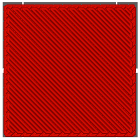 | Archimedean Spiral |  |
| Grid |  | Triangles |  |
| Stars |  | Gyroidal | 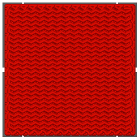 |
| Cubic |  | Octagonal Spiral |  |
| Concentric |  | Cubic Infill |  |
| Honeycomb |  | Adaptive Cubic Infill |  |
| Honeycomb 3D |  | ||
Disclaimer/Publisher’s Note: The statements, opinions and data contained in all publications are solely those of the individual author(s) and contributor(s) and not of MDPI and/or the editor(s). MDPI and/or the editor(s) disclaim responsibility for any injury to people or property resulting from any ideas, methods, instructions or products referred to in the content. |
© 2025 by the authors. Licensee MDPI, Basel, Switzerland. This article is an open access article distributed under the terms and conditions of the Creative Commons Attribution (CC BY) license (https://creativecommons.org/licenses/by/4.0/).
Share and Cite
Jasik, K.; Śnieżek, L.; Kluczyński, J. Additive Manufacturing of Metals Using the MEX Method: Process Characteristics and Performance Properties—A Review. Materials 2025, 18, 2744. https://doi.org/10.3390/ma18122744
Jasik K, Śnieżek L, Kluczyński J. Additive Manufacturing of Metals Using the MEX Method: Process Characteristics and Performance Properties—A Review. Materials. 2025; 18(12):2744. https://doi.org/10.3390/ma18122744
Chicago/Turabian StyleJasik, Katarzyna, Lucjan Śnieżek, and Janusz Kluczyński. 2025. "Additive Manufacturing of Metals Using the MEX Method: Process Characteristics and Performance Properties—A Review" Materials 18, no. 12: 2744. https://doi.org/10.3390/ma18122744
APA StyleJasik, K., Śnieżek, L., & Kluczyński, J. (2025). Additive Manufacturing of Metals Using the MEX Method: Process Characteristics and Performance Properties—A Review. Materials, 18(12), 2744. https://doi.org/10.3390/ma18122744