

Microstructure Evolution and Fracture Mode of Laser Welding–Brazing DP780 Steel-5754 Aluminum Alloy Joints with Various Laser Spot Positions


Abstract
1. Introduction
2. Experimental Procedures

| Elements | Si | Mn | Ti | Cu | Mg | Cr | Zn | C | P+S | Fe | Al |
|---|---|---|---|---|---|---|---|---|---|---|---|
| 5754 | 0.4 | 0.5 | - | 0.1 | 3.5 | 0.3 | 0.2 | - | - | 0.4 | Bal. |
| DP780 | ≤0.9 | ≤2.5 | - | - | - | - | - | ≤0.18 | ≤0.06 | Bal. | - |
| ER4043 | 5 | <0.05 | <0.15 | <0.05 | - | <0.05 | <0.1 | - | - | <0.6 | Bal. |
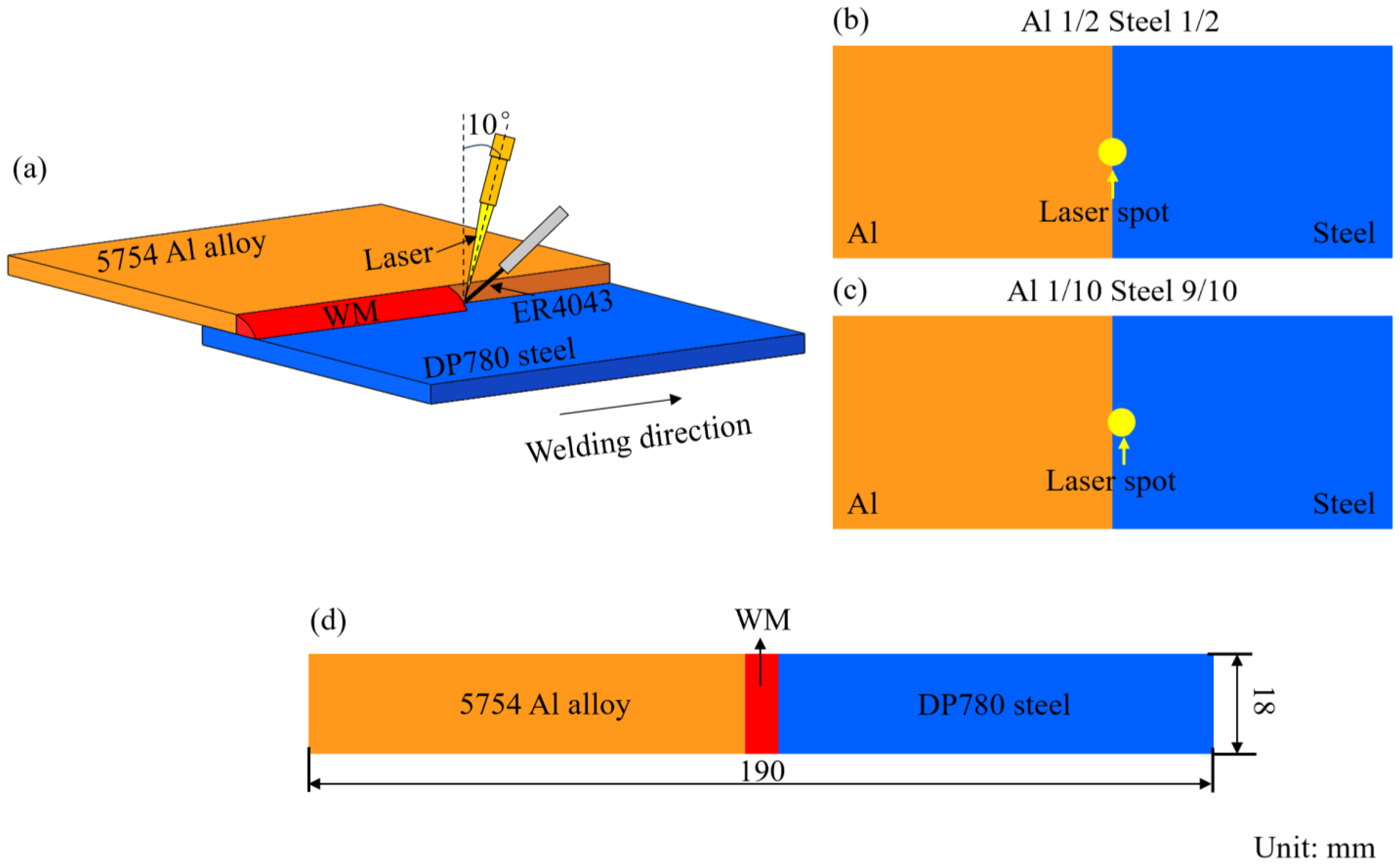
| Welding Parameters | #1 | #2 |
|---|---|---|
| Laser power, W | 1800 | |
| Welding speed, m/min | 0.36 | |
| Wire feed speed, m/min | 3.0 | |
| Laser tilt angle | 10° | |
| Position of laser spot | 50/50 (steel–Al) | 90/10 (steel–Al) |
3. Results and Discussion
4. Conclusions
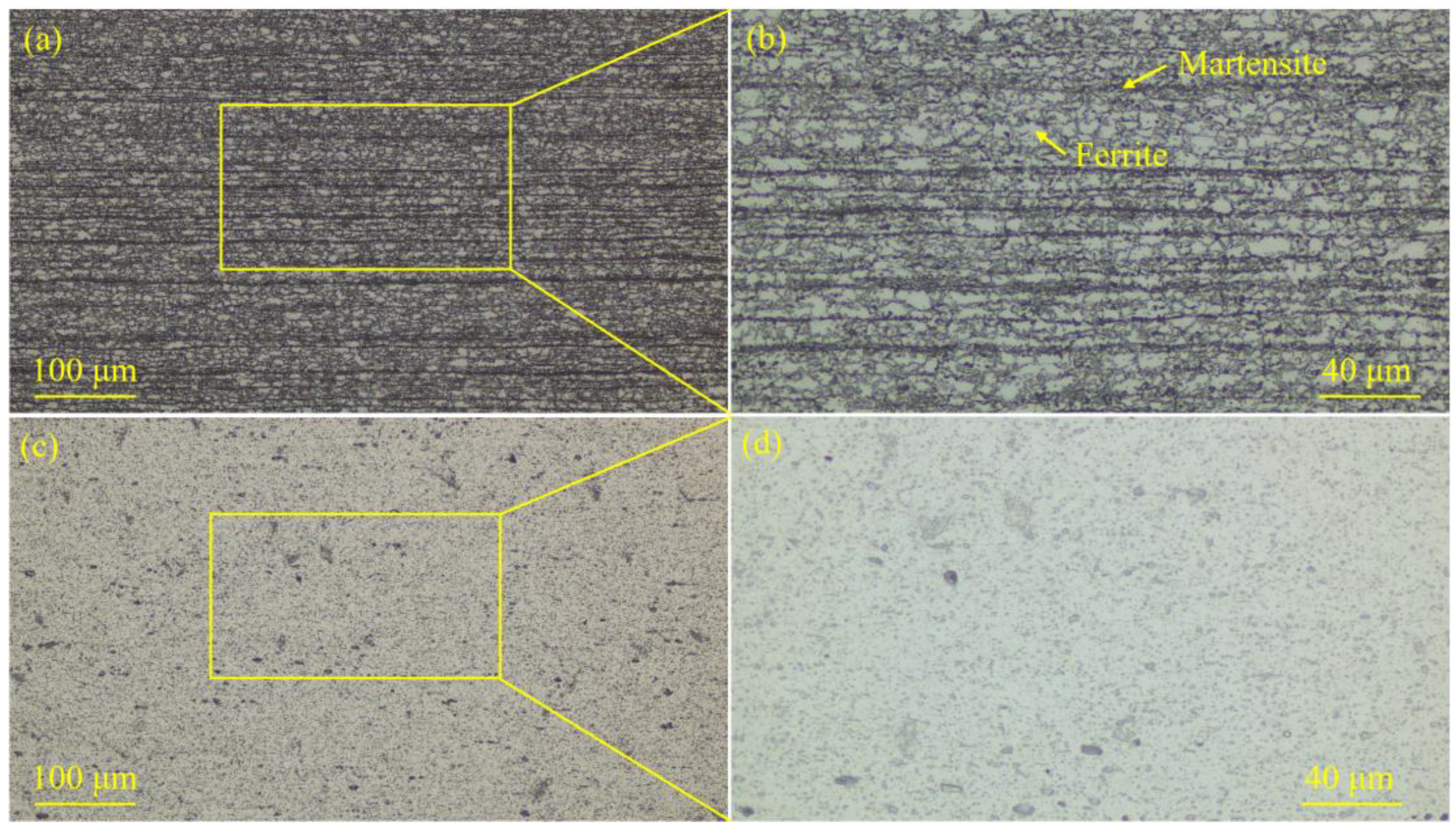
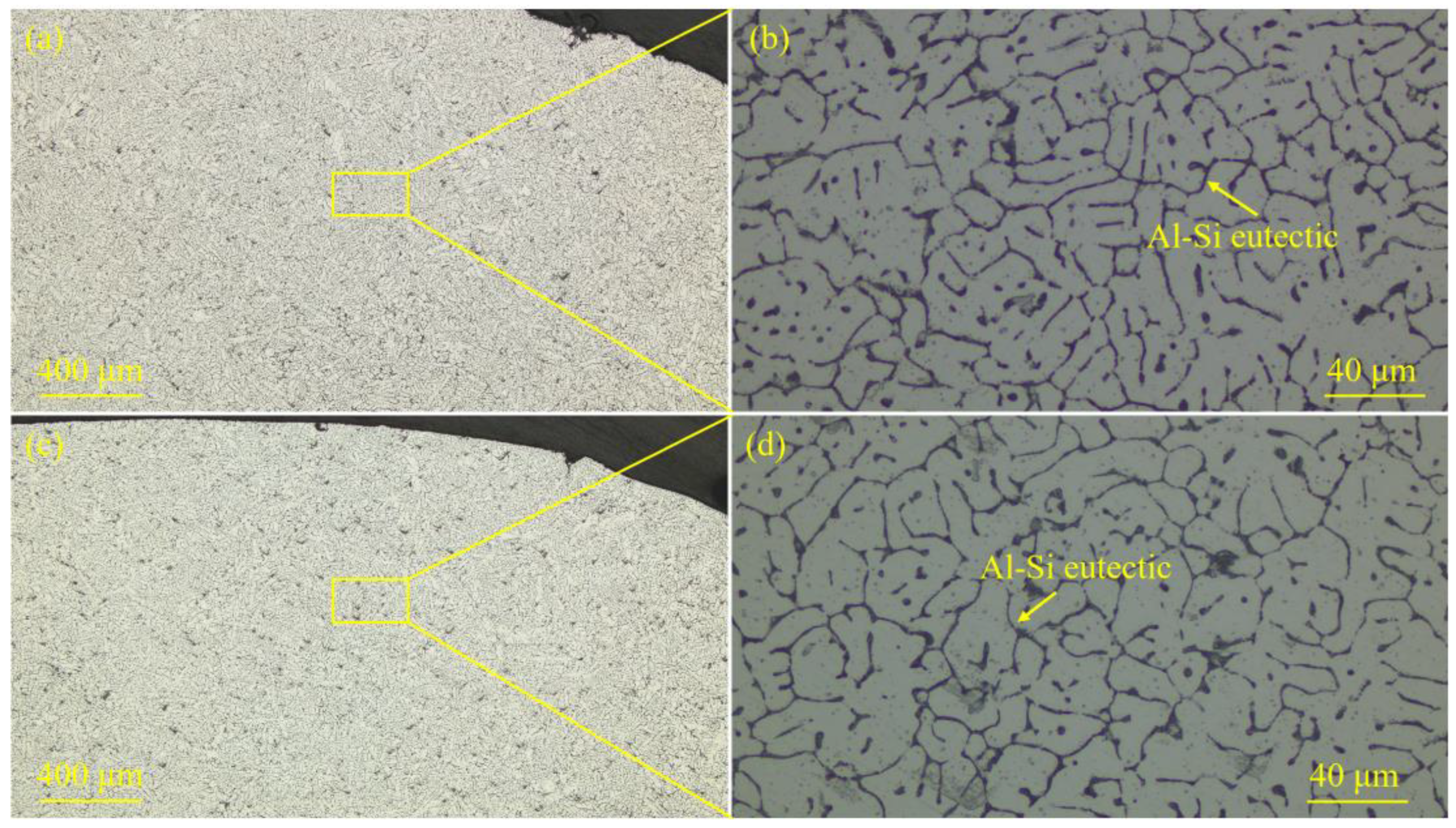
- (1)
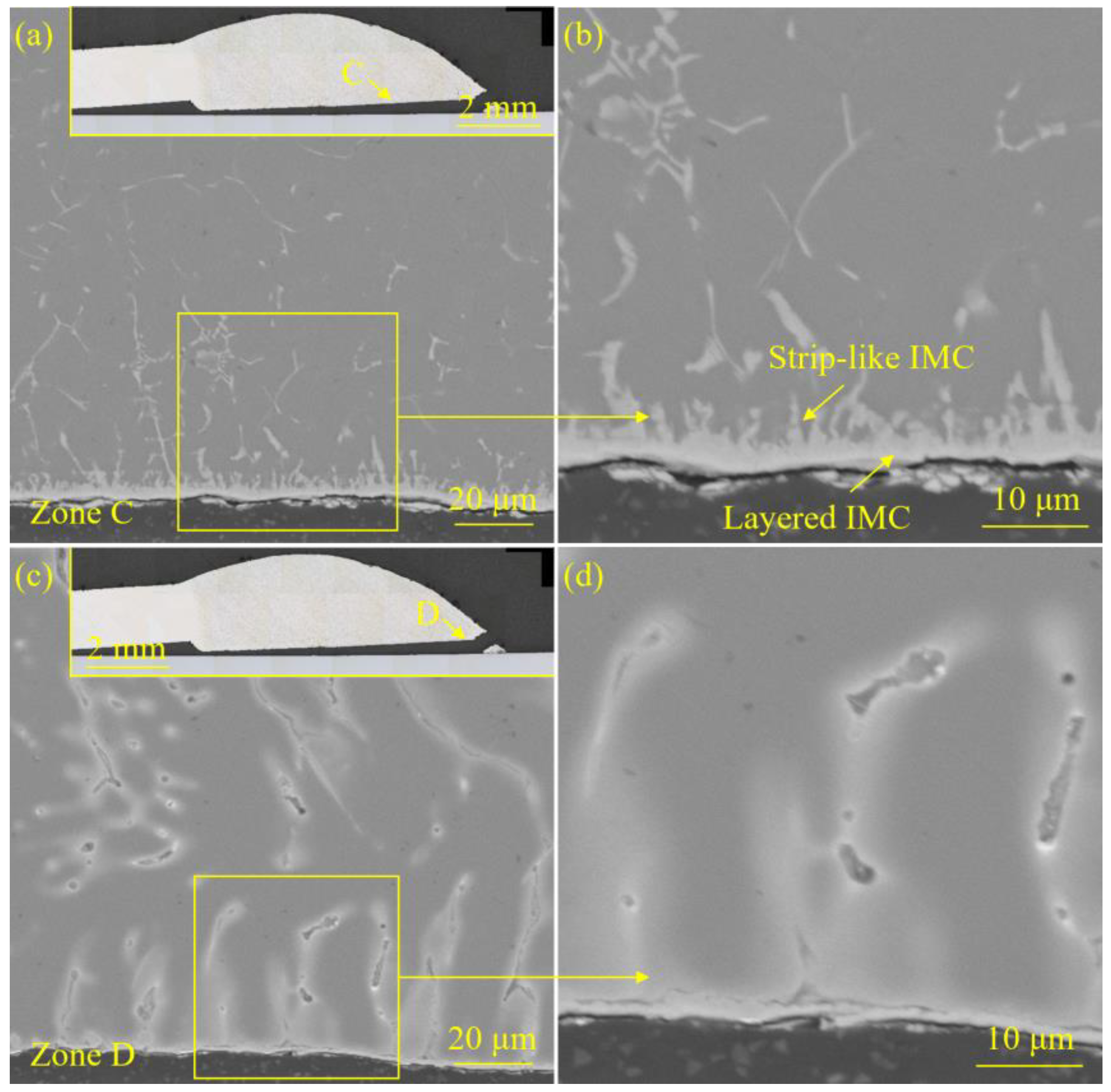
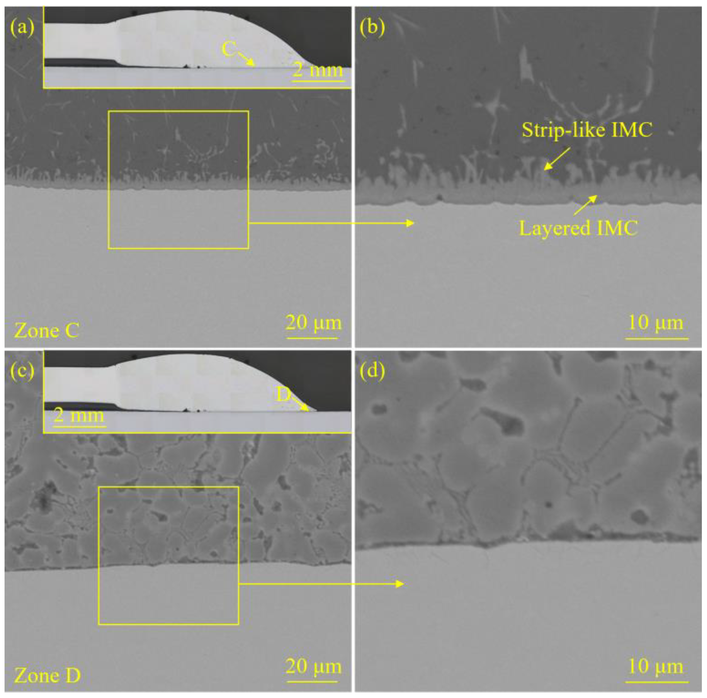
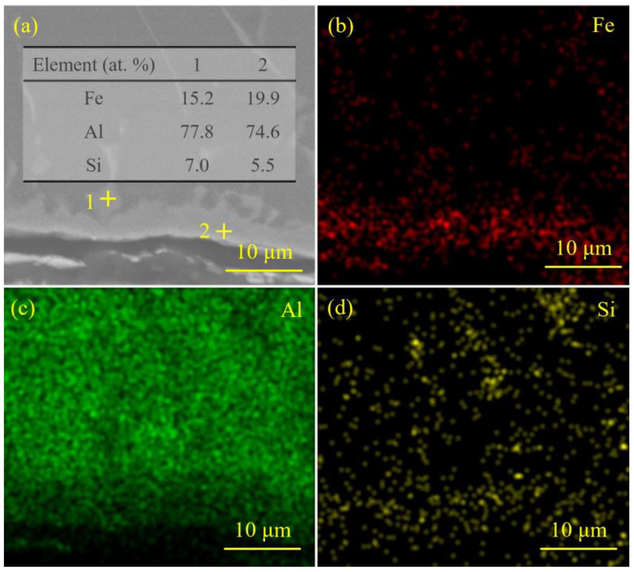
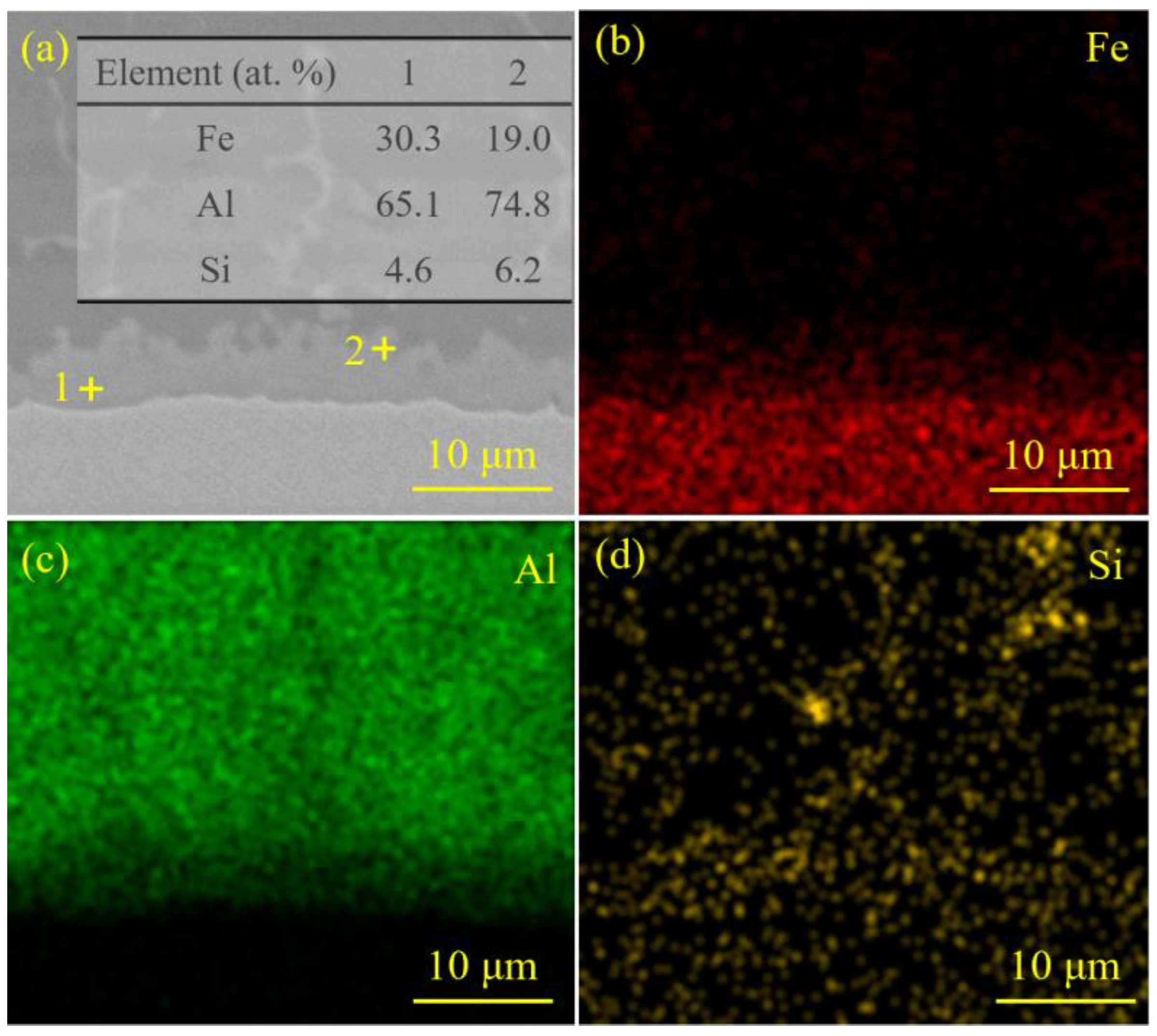
- The microstructure of the steel base metal (BM) was mainly composed of ferrite and martensite. The microstructure of the Al alloy BM was mainly α-Al. The weld seam microstructure of the steel–Al welded joints prepared with two laser spot positions was both α-Al matrix and Al-Si eutectic precipitated phases. The IMCs at the interface were all composed of elements Fe, Al, and Si.
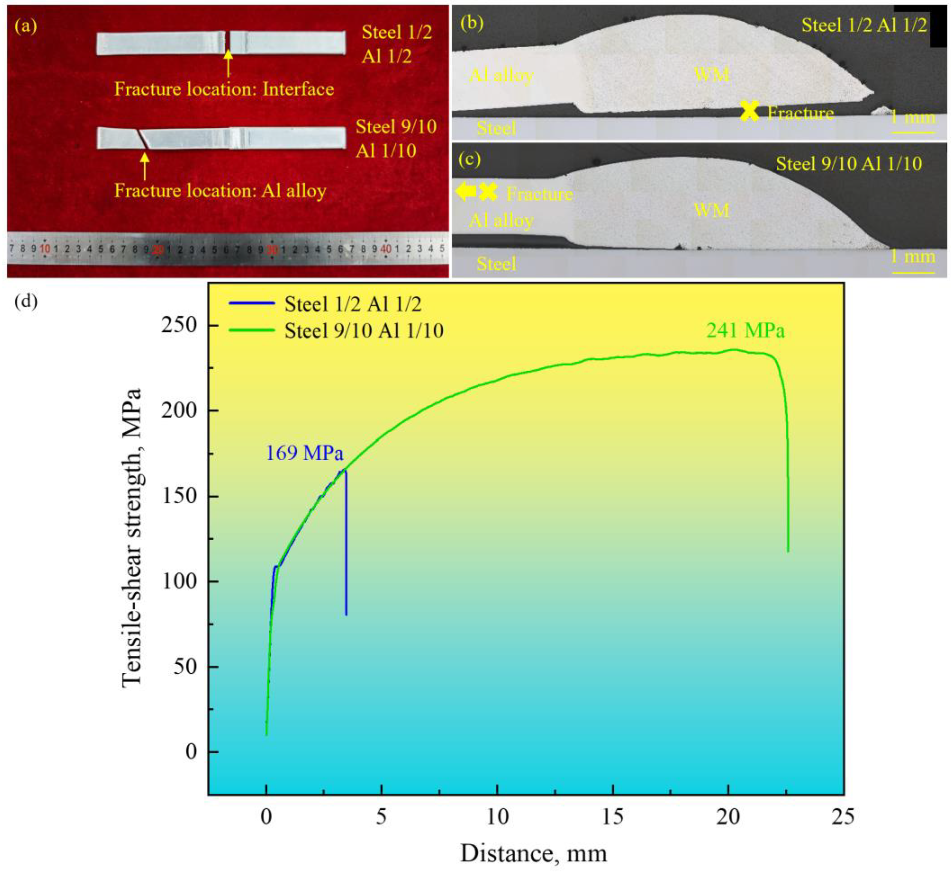
- (2)
- As the proportion of the laser spot on the steel BM increased from 50% to 90%, the tensile–shear strength of the steel–Al welding–brazing joint rose from 169 MPa to 241 MPa. The fracture location of the joint changed from the interface to the BM of the Al alloy, implying that the departure of the laser spot from the Al BM was favorable to prepare a qualified steel–Al welding–brazing joint.
- (3)
- A relatively small proportion (50%) of the laser spot on the steel BM could severely restrict the growth of intermetallic compounds (IMCs) and deteriorate the effect of interfacial metallurgical bonding of the steel–Al joint. In this case, the interfacial zone became the primary path for the crack propagation. The interface failure became the dominant failure mode of the steel–Al joint. As the proportion of the laser spot on the steel BM increased (to 90%), the metallurgical bonding at the interface was remarkably improved. The IMCs could effectively hinder the propagation of cracks along the interface. Eventually, the joint fractured at the BM of the Al alloy.
- (4)
- It is necessary to clarify the synergistic effects of various process parameters (laser spot position, welding speed, and laser power, etc.) on joint quality in future research. Moreover, the process window should be determined to achieve the qualified welding–brazing steel–Al joints in industry.
Author Contributions
Funding
Institutional Review Board Statement
Informed Consent Statement
Data Availability Statement
Conflicts of Interest
References
- Jiang, J.; Oliveira, J.P.; Yang, J.; Zheng, M.; Li, H.; Xu, W.; Wu, L.; Dou, T.; Wang, R.; Tan, C.; et al. Effect of defocusing distance on interfacial reaction and mechanical properties of dissimilar laser Al/steel joints with a porous high entropy alloy coating. Mater. Charact. 2024, 210, 113751. [Google Scholar] [CrossRef]
- Baek, S.; Kim, J.; Kwak, T.; Lee, T.; Lee, H.C.; Chen, C.T.; Geng, P.H.; Ma, N.S.; Lee, S.J.; Kim, D.J. Al heat affected zone-less resistance element welded lap joints of Al alloy and 1 GPa class steel: Transition of microstructure and fracture with heat transfer. J. Mater. Res. Technol. 2024, 28, 3541–3565. [Google Scholar] [CrossRef]
- Zeng, Y.J.; Yang, J.; Dou, T.Y.; Zheng, M.; Ye, X.; Liang, Y.; Liu, H.B.; Xue, J.; Zhang, H. Influence of surface pretreatment of steel substrate on the interfacial microstructure and tensile properties of laser Al/steel joints. Mater. Lett. 2024, 377, 137523. [Google Scholar] [CrossRef]
- Dinda, S.K.; Sk, M.B.; Roy, G.G.; Srirangam, P. Microstructure and mechanical properties of electron beam welded dissimilar steel to Fe-Al alloy joints. Mater. Sci. Eng. A 2016, 677, 182–192. [Google Scholar] [CrossRef]
- Dinda, S.K.; Roy, G.G.; Srirangam, P. Synchrotron diffraction and TEM characterization of intermetallics formation in EB-welded DP steel to Al alloy dissimilar joints. Vacuum 2023, 218, 112626. [Google Scholar] [CrossRef]
- Du, M.; Wang, W.; Zhang, X.; Niu, J. Effect of process parameters on performances of TWIP steel/Al alloy dissimilar metals butt joints by laser offset welding. Mater. Sci. Eng. A 2022, 853, 143746. [Google Scholar] [CrossRef]
- Das, T.; Das, R.; Paul, J. Resistance spot welding of dissimilar AISI-1008 steel/Al-1100 alloy lap joints with a graphene interlayer. J. Manuf. Process. 2020, 53, 260–274. [Google Scholar] [CrossRef]
- Dash, S.S.; Biswas, S.; Peng, H.; Jiang, X.Q.; Li, D.Y.; Chen, D.L. Deformation behavior of dissimilar ultrasonic spot-welded joints of a clad 7075 aluminum alloy to galvanized high-strength low-alloy steel. Mater. Sci. Eng. A 2024, 894, 146179. [Google Scholar] [CrossRef]
- Zhao, Q.; Ma, H.; Qin, G. On the formation of interfacial compounds in the 2A14 Al alloy/steel friction welded joint: A comparative study. J. Manuf. Process. 2022, 83, 398–413. [Google Scholar] [CrossRef]
- Zhang, D.; Qin, G.; Ma, H.; Geng, P. Non-uniformity of intermetallic compounds and properties in inertia friction welded joints of 2A14 Al alloy to 304 stainless steel. J. Manuf. Process. 2021, 68, 834–842. [Google Scholar] [CrossRef]
- Shan, H.; Ma, Y.; Yang, B.; Feng, Q.; Li, Y.; Lin, Z. Elucidation of interface joining mechanism of aluminum alloy/dual-phase steel friction stir riveting (FSR) joint. J. Mater. Res. Technol. 2023, 25, 6792–6811. [Google Scholar] [CrossRef]
- Jiang, Q.; Yang, J.; Xiao, R.; Zheng, M.; Jiang, J.; Xue, J.; Xu, W.; Xu, J.; Zhang, H. Outstanding ductility of dissimilar laser Al/steel spot joint using a high entropy alloy interlayer. Mater. Lett. 2023, 349, 134707. [Google Scholar] [CrossRef]
- Gao, K.; Gu, H.; Gong, J.; Li, K.; Dai, X.; Ye, K. Microstructure and mechanical properties of induction rolling welded joint for A283GRC steel and 5052 aluminum alloy. J. Mater. Process. Technol. 2023, 318, 118016. [Google Scholar] [CrossRef]
- Li, Y.D.; Teng, J.W.; Wang, J.; Wang, H.; Liu, Q.L.; Lai, R.L.; Yang, B.B.; Wang, Z.C.; Li, Y.Q. Interfacial corrosion behavior of aluminum/steel joints prepared by solid-state additive manufacturing. Corros. Sci. 2025, 244, 112650. [Google Scholar] [CrossRef]
- Xu, Y.; Chen, Q.W.; Wang, B.X.; Qiu, F.; Dong, B.X.; Li, H.J.; Feng, Z.D.; Barber, G.C. Dissimilar joining of aluminum alloy and low-alloy carbon steel by resistance spot welding. J. Mater. Res. Technol. 2024, 33, 919–928. [Google Scholar] [CrossRef]
- Mortazavi, S.N.; Marashi, P.; Pouranvari, M.; Masoumi, M. Investigation on joint strength of dissimilar resistance spot welds of aluminum alloy and low carbon steel. Adv. Mater. Res. 2011, 264–265, 384–389. [Google Scholar] [CrossRef]
- Zhou, K.; Yu, W.; Ren, B.; Wang, G.; Yao, P. Microstructure and mechanical properties of resistance spot welded dissimilar aluminum/steel joints fabricated using high entropy alloy as interlayer. Mater. Charact. 2024, 216, 114278. [Google Scholar] [CrossRef]
- Geng, P.H.; Morimuraa, M.; Ma, H.; Ma, Y.W.; Ma, N.S.; Liu, H.H.; Aokia, Y.; Fujii, H.; Qin, G.L. Elucidation of intermetallic compounds and mechanical properties of dissimilar friction stir lap welded 5052 Al alloy and DP590 steel. J. Alloys Compd. 2022, 906, 164381. [Google Scholar] [CrossRef]
- Zhang, M.; Wang, Y.D.; Xue, P.; Zhang, H.; Ni, D.R.; Wang, K.S.; Ma, Z.Y. High-quality dissimilar friction stir welding of Al to steel with no contacting between tool and steel plate. Mater. Charact. 2022, 191, 112128. [Google Scholar] [CrossRef]
- Geng, H.H.; Sun, L.Q.; Li, G.Y.; Cui, J.J.; Huang, L.; Xu, Z.D. Fatigue fracture properties of magnetic pulse welded dissimilar Al-Fe lap joints. Int. J. Fatigue 2019, 121, 146–154. [Google Scholar] [CrossRef]
- Dang, H.Q.; Yu, H.P. Improving the quality of Al-Fe tube joints manufactured via magnetic pulse welding using an inclined-wall field shaper. J. Manuf. Process. 2022, 73, 78–89. [Google Scholar] [CrossRef]
- Chen, X.; Inao, D.; Tanaka, S.; Mori, A.; Li, X.; Hokamoto, K. Explosive welding of Al alloys and high strength duplex stainless steel by controlling energetic conditions. J. Manuf. Process. 2020, 58, 1318–1333. [Google Scholar] [CrossRef]
- Torkamany, M.J.; Tahamtan, S.; Sabbaghzadeh, J. Dissimilar welding of carbon steel to 5754 aluminum alloy by Nd: YAG pulsed laser. Mater. Des. 2010, 31, 458–465. [Google Scholar] [CrossRef]
- Xia, H.B.; Yang, B.Y.; Han, Y.D.; Xu, L.Y.; Tan, C.W.; Li, L.Q.; Li, H.Y.; Zhao, X.Y.; Zhang, K.P.; Su, X.; et al. Toward understanding the fractured mechanism in laser welded-brazed Al/steel interface by in-situ SEM tensile observations. J. Mater. Process. Technol. 2024, 325, 118294. [Google Scholar] [CrossRef]
- Li, L.Q.; Xia, H.B.; Tan, C.W.; Ma, N.S. Influence of laser power on interfacial microstructure and mechanical properties of laser welded-brazed Al/steel dissimilar butted joint. J. Manuf. Process. 2018, 32, 160–174. [Google Scholar] [CrossRef]
- Dharmendra, C.; Rao, K.P.; Wilden, J.; Reich, S. Study on laser welding–brazing of zinc coated steel to aluminum alloy with a zinc based filler. Mater. Sci. Eng. A 2011, 528, 1497–1503. [Google Scholar] [CrossRef]
- Ding, K.; Hu, T.H.; Wu, T.H.; Dong, W.F.; Zhu, P.; Wang, S.J.; Pan, H.; Gao, Y.L. Role of the position of the laser spot in the failure transition during the tensile test for the laser welding-brazing of galvanized CRRA1000 steel to 5754 aluminum alloy in an overlapped joint. Mater. Sci. Eng. A 2013, 880, 145314. [Google Scholar] [CrossRef]
- Yan, F.; Zhang, K.; Yang, B.; Chen, Z.; Zhu, Z.; Wang, C. Interface characteristics and reaction mechanism of steel/Al welds produced by magnetic field assisted laser welding-brazing. Opt. Laser Technol. 2021, 138, 106843. [Google Scholar] [CrossRef]
- Yang, B.Y.; Li, H.Y.; Sun, H.F.; Xu, W.T.; Xia, H.B.; Su, X.; Chen, B.; Song, X.G.; Tan, C.W. Towards enhanced mechanical performance of Al/steel welded-brazed joints via laser surface texturing modification. J. Mater. Res. Technol. 2023, 27, 5278–5290. [Google Scholar] [CrossRef]
- Xia, H.; Li, L.; Ma, N.; Tan, C.; Gong, J. Influence of energy ratio on dual-spot laser welded-brazed Al/steel butt joint. J. Mater. Process. Technol. 2020, 281, 116624. [Google Scholar] [CrossRef]
- Yang, B.; Lin, D.; Xia, H.; Li, H.; Wang, P.; Jiao, J.; Chen, X.; Tan, C.; Li, L.; Wang, Q.; et al. Welding characterization evolutions for dual spot laser welded-brazed Al/steel joint with various spot configurations. J. Mater. Res. Technol. 2022, 19, 697–708. [Google Scholar] [CrossRef]
- Xia, H.; Tao, W.; Li, L.; Tan, C.; Zhang, K.; Ma, N. Effect of laser beam models on laser welding–brazing Al to steel. Opt. Laser Technol. 2020, 122, 105845. [Google Scholar] [CrossRef]
- Nakhaie, D.; Kosari, A.; Mol, J.M.C.; Asselin, E. Corrosion resistance of hot-dip galvanized steel in simulated soil solution: A factorial design and pit chemistry study. Corros. Sci. 2020, 164, 108310. [Google Scholar] [CrossRef]
- Wang, Y.; Xu, Y.; Liu, R.; Peng, F.; Gu, X.; Zhang, T.; Hou, X.; Sun, W. Microstructure evolution and mechanical behavior of a novel hot-galvanized Q&P steel subjected to high-temperature short-time overaging treatment. Mater. Sci. Eng. A 2020, 789, 139665. [Google Scholar] [CrossRef]
- Mercan, E.; Ayan, Y.; Kahraman, N. Investigation on joint properties of AA5754 and AA6013 dissimilar aluminum alloys welded using automatic GMAW. Eng. Sci. Technol. Int. J. 2020, 23, 723–731. [Google Scholar] [CrossRef]
- Xia, H.; Zhao, X.; Tan, C.; Chen, B.; Song, X.; Li, L. Effect of Si content on the interfacial reactions in laser welded-brazed Al/steel dissimilar butted joint. J. Mater. Process. Technol. 2018, 258, 9–21. [Google Scholar] [CrossRef]
- GB/T 26957-2022; Destructive Tests on Welds in Metallic Materials—Tensile Test on Cruciform and Lapped Joints. State Administration for Market Regulation: Beijing, China, 2022.
- Li, B.L.; Zhou, J.Y.; Pan, H.; Sun, Y.; Wu, T.H.; Gao, Y.L. Control of the intermetallic compound of the laser welding-brazing steel-Al joint and its effect on the joint property. J. Mater. Res. Technol. 2025, 36, 2839–2848. [Google Scholar] [CrossRef]
- Li, B.L.; Hu, T.H.; Zhou, J.Y.; Pan, H.; Ding, K.; Wu, T.H.; Gao, Y.L. Interfacial microstructure characteristics and failure mechanism of the laser welding-brazing steel-Al joints with various welding parameters. J. Mater. Res. Technol. 2024, 31, 2498–2507. [Google Scholar] [CrossRef]
- Hu, Y.; Zhang, Y.; Mi, G.; Wang, C.; Zhang, W.; Zhang, X. Effects of Si contents in filling wires on microstructure evolution and properties of Al-steel dissimilar joint by laser welding-brazing. J. Mater. Res. Technol. 2021, 15, 1896–1904. [Google Scholar] [CrossRef]
- Zhang, X.; Gao, K.; Xiong, X.; Hu, X.; Wang, Z.; Wang, J.; Wei, W.; Wu, X.; Wen, S.; Huang, H.; et al. Effect of Si addition to Fe on the formation and growth of intermetallic compounds in Fe/Al composites. J. Mater. Res. Technol. 2024, 28, 1294–1302. [Google Scholar] [CrossRef]


Disclaimer/Publisher’s Note: The statements, opinions and data contained in all publications are solely those of the individual author(s) and contributor(s) and not of MDPI and/or the editor(s). MDPI and/or the editor(s) disclaim responsibility for any injury to people or property resulting from any ideas, methods, instructions or products referred to in the content. |
© 2025 by the authors. Licensee MDPI, Basel, Switzerland. This article is an open access article distributed under the terms and conditions of the Creative Commons Attribution (CC BY) license (https://creativecommons.org/licenses/by/4.0/).
Share and Cite
Li, B.; Zhou, J.; Hu, R.; Pan, H.; Wu, T.; Gao, Y. Microstructure Evolution and Fracture Mode of Laser Welding–Brazing DP780 Steel-5754 Aluminum Alloy Joints with Various Laser Spot Positions. Materials 2025, 18, 2676. https://doi.org/10.3390/ma18122676
Li B, Zhou J, Hu R, Pan H, Wu T, Gao Y. Microstructure Evolution and Fracture Mode of Laser Welding–Brazing DP780 Steel-5754 Aluminum Alloy Joints with Various Laser Spot Positions. Materials. 2025; 18(12):2676. https://doi.org/10.3390/ma18122676
Chicago/Turabian StyleLi, Bolong, Jiayi Zhou, Rongxun Hu, Hua Pan, Tianhai Wu, and Yulai Gao. 2025. "Microstructure Evolution and Fracture Mode of Laser Welding–Brazing DP780 Steel-5754 Aluminum Alloy Joints with Various Laser Spot Positions" Materials 18, no. 12: 2676. https://doi.org/10.3390/ma18122676
APA StyleLi, B., Zhou, J., Hu, R., Pan, H., Wu, T., & Gao, Y. (2025). Microstructure Evolution and Fracture Mode of Laser Welding–Brazing DP780 Steel-5754 Aluminum Alloy Joints with Various Laser Spot Positions. Materials, 18(12), 2676. https://doi.org/10.3390/ma18122676