
Calcium Phosphate Honeycomb Scaffolds with Tailored Microporous Walls Using Phase Separation-Assisted Digital Light Processing


Highlights
- Dual-scale porosity CaP honeycomb scaffolds were manufactured;
- Camphene was employed as the porogen for DLP;
- Microporosity of CaP walls was tailored by adjusting the camphene content;
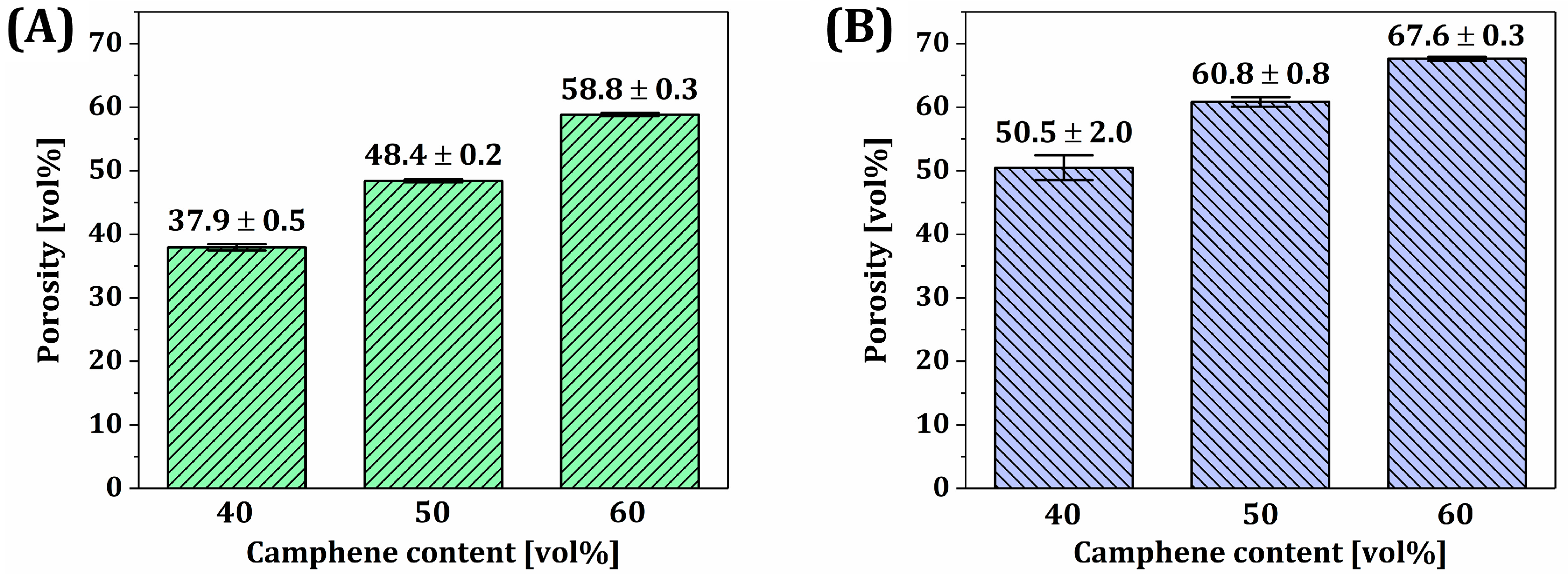
- Overall porosity increased with an increase in microporosity;
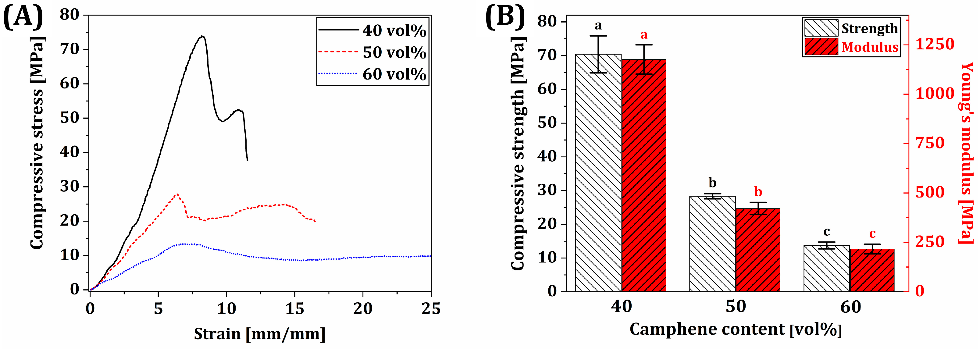
- Mechanical properties increased with a decrease in microporosity.
Abstract
1. Introduction
2. Materials and Methods
2.1. Compositions of BCP Suspensions
2.2. Preparation of BCP Suspensions
2.3. Characterization of BCP Powder and Suspensions
2.4. Digital Light Processing (DLP) Fabrication
2.5. Post-Processing and Sintering
2.6. Characterization of Scaffolds
2.7. Measurement of Compressive Strengths and Modulus
2.8. Evaluation of Water Penetration Ability
2.9. Statistical Analysis
3. Results and Discussion
3.1. Characterization of BCP Powders
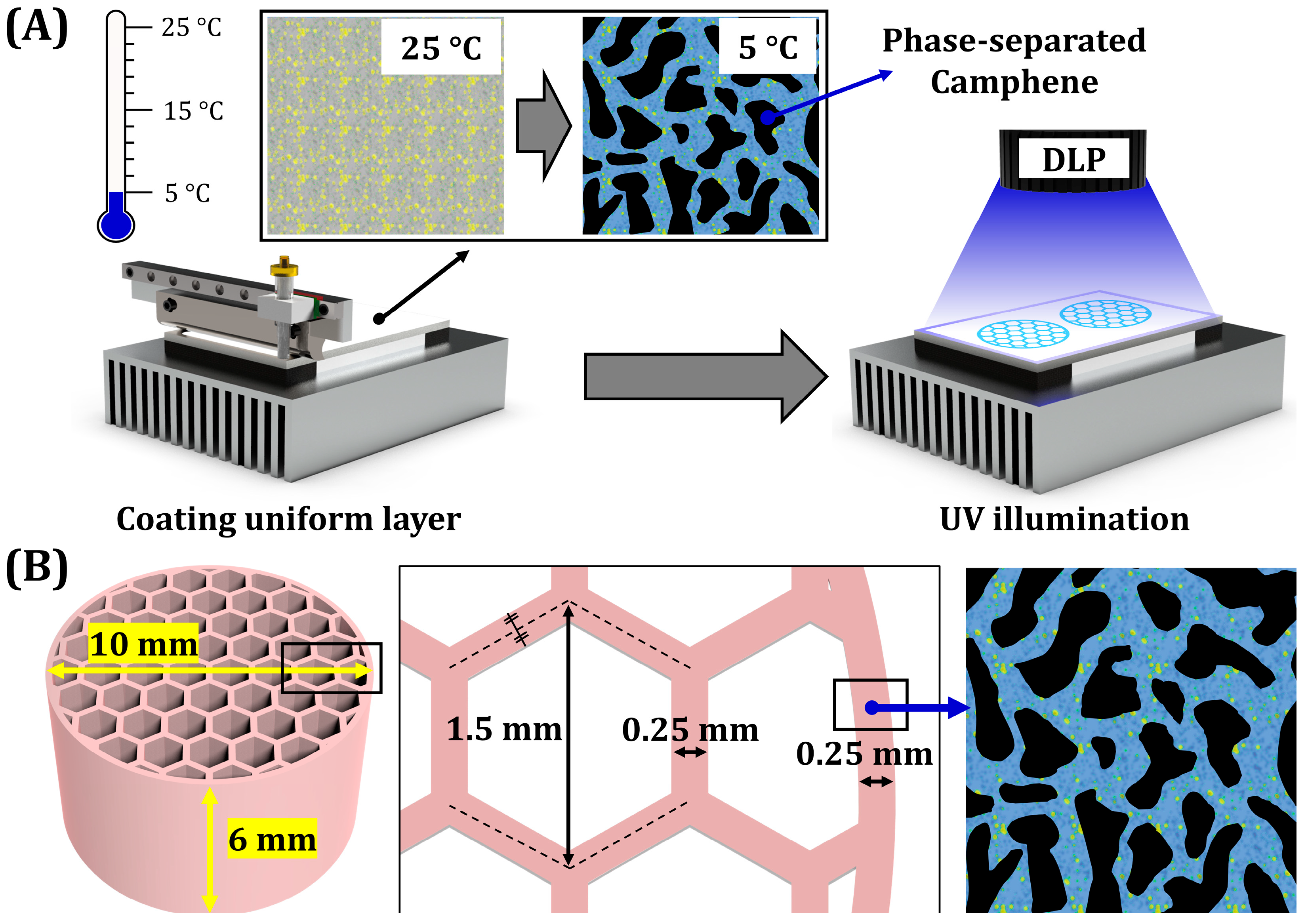
3.2. Phase Separation Behavior of BCP Suspensions
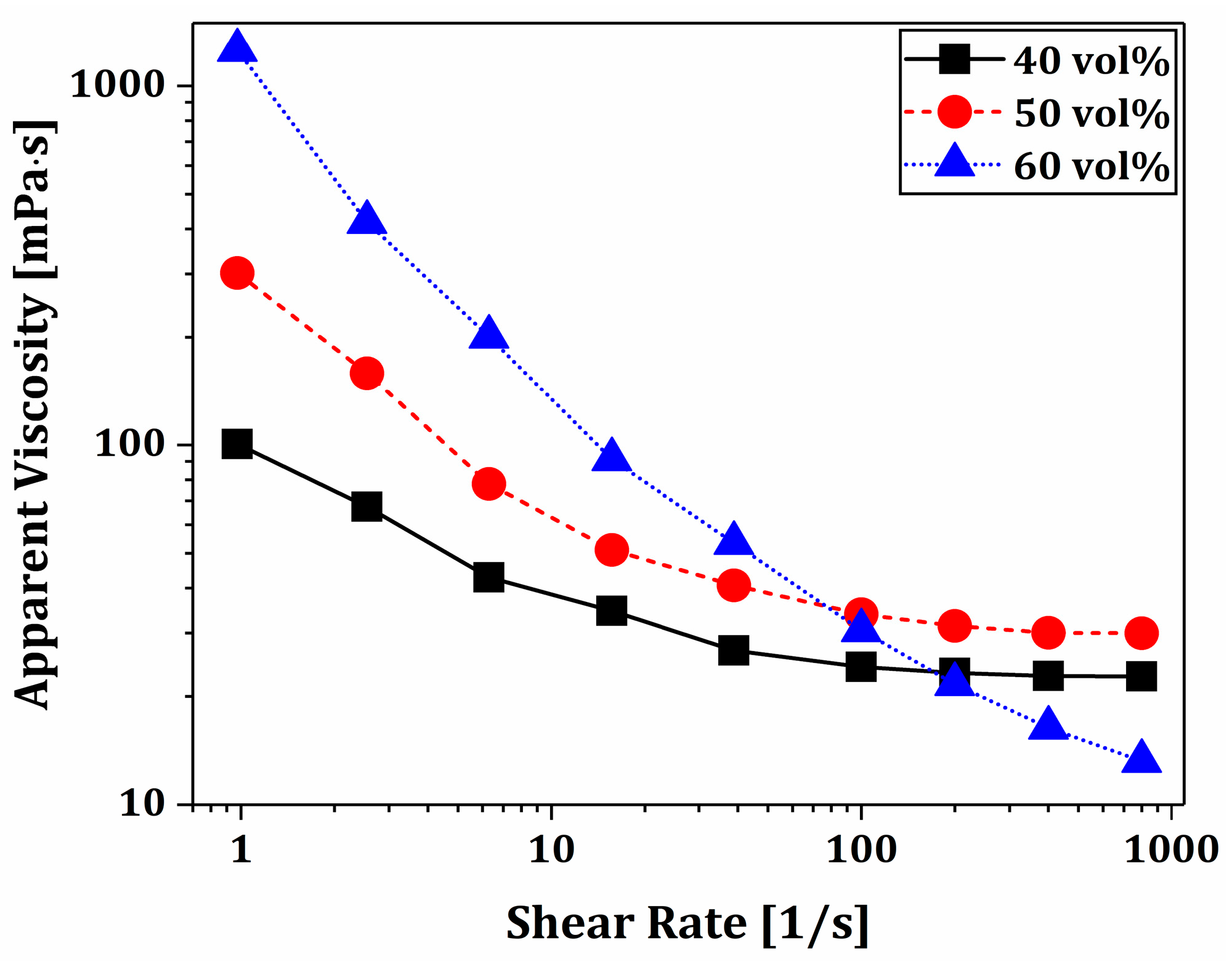
3.3. Rheological Behaviors of BCP Suspensions
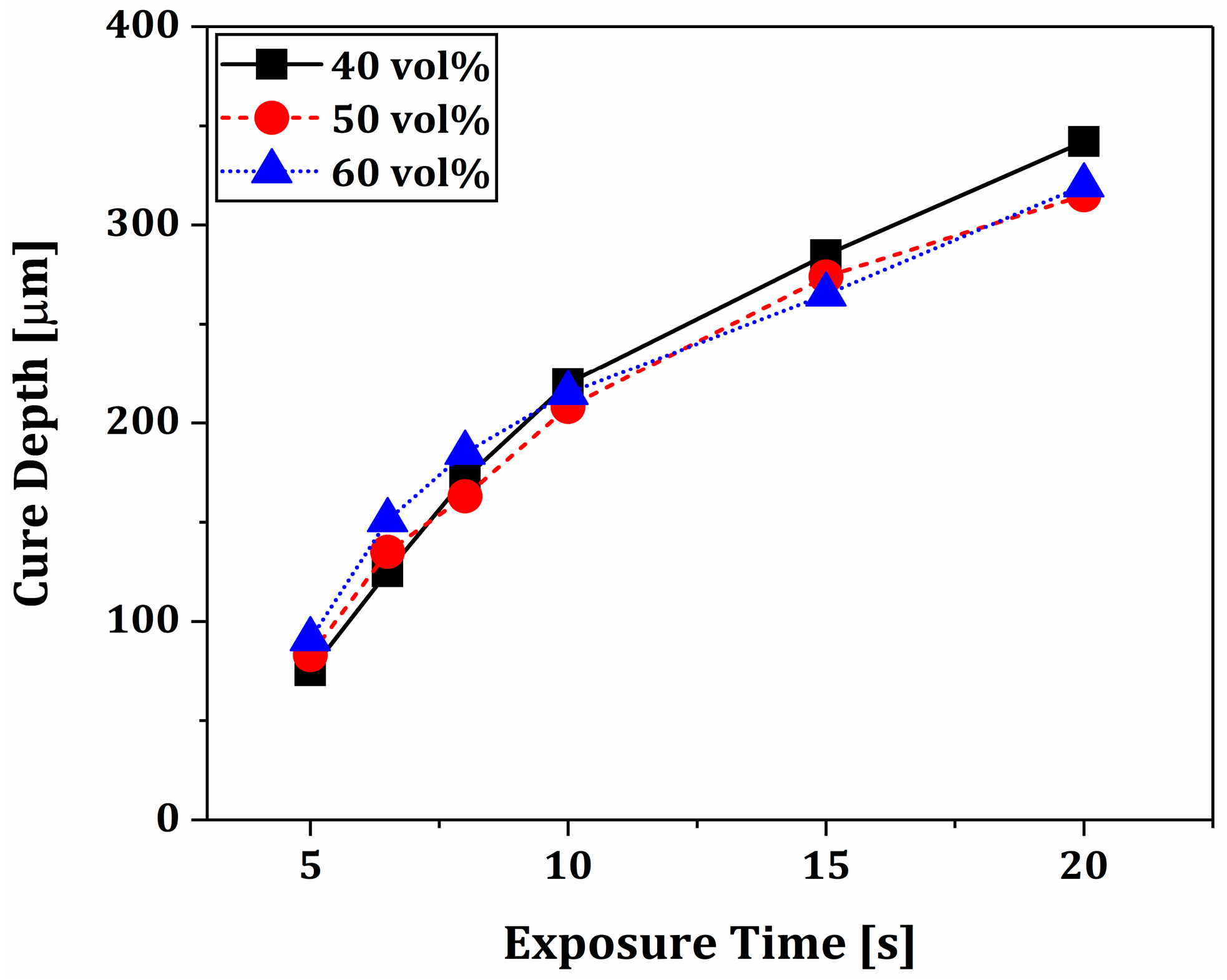
3.4. Photopolymerization Behaviors of Phase-Separated BCP Layers
3.5. Macrostructures and Microstructures of As-Manufactured Macroporous BCP Scaffolds
3.6. Macrostructures of Sintered Dual-Scale Porosity BCP Scaffolds
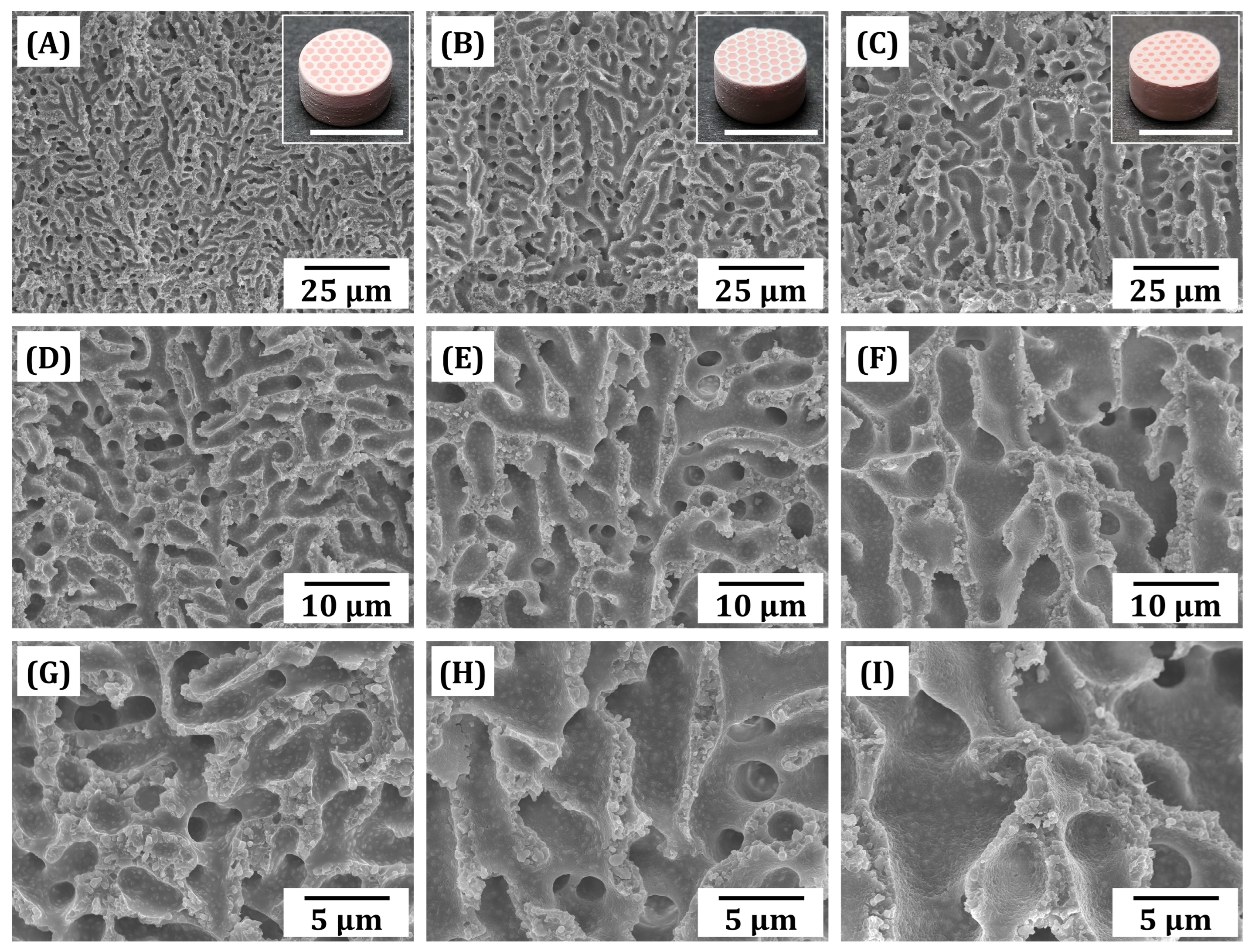
3.7. Microporous Structure of Sintered BCP Frameworks
3.8. Crystalline Phases of Sintered BCP Scaffolds
3.9. Overall Porosities, Macroporosities, and Microporosities of Dual-Scale Porosity BCP Scaffolds
3.10. Mechanical Properties of BCP Scaffolds
3.11. Mass Transport Abilities of Dual-Scale Porosity BCP Scaffolds
4. Conclusions
Author Contributions
Funding
Institutional Review Board Statement
Informed Consent Statement
Data Availability Statement
Conflicts of Interest
References
- Min, K.H.; Kim, D.H.; Kim, K.H.; Seo, J.H.; Pack, S.P. Biomimetic Scaffolds of Calcium-Based Materials for Bone Regeneration. Biomimetics 2024, 9, 511. [Google Scholar] [CrossRef] [PubMed]
- Tavoni, M.; Dapporto, M.; Tampieri, A.; Sprio, S. Bioactive Calcium Phosphate-Based Composites for Bone Regeneration. J. Compos. Sci. 2021, 5, 227. [Google Scholar] [CrossRef]
- Jeong, J.; Kim, J.H.; Shim, J.H.; Hwang, N.S.; Heo, C.Y. Bioactive calcium phosphate materials and applications in bone regeneration. Biomater. Res. 2019, 23, 4. [Google Scholar] [CrossRef]
- Bouler, J.M.; Pilet, P.; Gauthier, O.; Verron, E. Biphasic calcium phosphate ceramics for bone reconstruction: A review of biological response. Acta Biomater. 2017, 53, 1–12. [Google Scholar] [CrossRef]
- Denry, I.; Kuhn, L.T. Design and characterization of calcium phosphate ceramic scaffolds for bone tissue engineering. Dent. Mater. 2016, 32, 43–53. [Google Scholar] [CrossRef]
- Bose, S.; Tarafder, S. Calcium phosphate ceramic systems in growth factor and drug delivery for bone tissue engineering: A review. Acta Biomater. 2012, 8, 1401–1421. [Google Scholar] [CrossRef] [PubMed]
- Johnson, A.J.W.; Herschler, B.A. A review of the mechanical behavior of CaP and CaP/polymer composites for applications in bone replacement and repair. Acta Biomater. 2011, 7, 16–30. [Google Scholar] [CrossRef]
- Vijayan, A.; Vishnu, J.; Revathi, A.; Shankar, B.; Sambhudevan, S. A review on hydroxyapatite fabrication: From powders to additive manufactured scaffolds. Biomater. Sci. 2025, 13, 913–945. [Google Scholar] [CrossRef]
- Budharaju, H.; Suresh, S.; Sekar, M.P.; De Vega, B.; Sethuraman, S.; Sundaramurthi, D.; Kalaskar, D.M. Ceramic materials for 3D printing of biomimetic bone scaffolds—Current state-of-the-art & future perspectives. Mater. Des. 2023, 231, 112064. [Google Scholar]
- Beheshtizadeh, N.; Azami, M.; Abbasi, H.; Farzin, A. Applying extrusion-based 3D printing technique accelerates fabricating complex biphasic calcium phosphate-based scaffolds for bone tissue regeneration. J. Adv. Res. 2022, 40, 69–94. [Google Scholar] [CrossRef]
- Du, X.; Fu, S.; Zhu, Y. 3D printing of ceramic-based scaffolds for bone tissue engineering: An overview. J. Mater. Chem. B 2018, 6, 4397–4412. [Google Scholar] [CrossRef] [PubMed]
- Trombetta, R.; Inzana, J.A.; Schwarz, E.M.; Kates, S.L.; Awad, H.A. 3D Printing of Calcium Phosphate Ceramics for Bone Tissue Engineering and Drug Delivery. Ann. Biomed. Eng. 2017, 45, 23–44. [Google Scholar] [CrossRef] [PubMed]
- Wen, Y.; Sun, X.; Meng, H.; Sun, B.; Chen, P.; Liu, X.; Zhang, K.; Yang, X.; Peng, J.; Lu, S. 3D printed porous ceramic scaffolds for bone tissue engineering: A review. Biomater. Sci. 2017, 5, 1690–1698. [Google Scholar] [CrossRef] [PubMed]
- Hwa, L.C.; Rajoo, S.; Noor, A.M.; Ahmad, N.; Uday, M.B. Recent advances in 3D printing of porous ceramics: A review. Curr. Opin. Solid State Mater. Sci. 2017, 21, 323–347. [Google Scholar] [CrossRef]
- Wu, Y.; Liu, P.; Feng, C.; Cao, Q.; Xu, X.; Liu, Y.; Li, X.; Zhu, X.; Zhang, X. 3D printing calcium phosphate ceramics with high osteoinductivity through pore architecture optimization. Acta Biomater. 2024, 185, 111–125. [Google Scholar] [CrossRef]
- Mohammed Mohammed, A.H.; Shariff, K.A.; Wahjuningrum, D.A.; Bakar, M.H.A.; Mohamad, H. A comprehensive review of the effects of porosity and macro- and micropore formations in porous β-TCP scaffolds on cell responses. J. Aust. Ceram. Soc. 2023, 59, 865–879. [Google Scholar] [CrossRef]
- Bobbert, F.S.L.; Zadpoor, A.A. Effects of bone substitute architecture and surface properties on cell response, angiogenesis, and structure of new bone. J. Mater. Chem. B 2017, 5, 6175–6192. [Google Scholar] [CrossRef]
- Sun, Y.; Wang, Y.; Dong, B.; Yang, P.; Ji, C.; Li, Y.; Ma, J.; Ma, X. Understanding the relationship between pore structure and properties of triply periodic minimal surface bone scaffolds. J. Mater. Sci. Mater. Med. 2025, 36, 6. [Google Scholar] [CrossRef]
- Zhao, H.; Li, L.; Ding, S.; Liu, C.; Ai, J. Effect of porous structure and pore size on mechanical strength of 3D-printed comby scaffolds. Mater. Lett. 2018, 223, 21–24. [Google Scholar] [CrossRef]
- Koushik, T.M.; Miller, C.M.; Antunes, E. Graded hydroxyapatite triply periodic minimal surface structures for bone tissue engineering applications. Adv. Healthc. Mater. 2025, 2402953. [Google Scholar] [CrossRef]
- Yao, Y.; Qin, W.; Xing, B.; Sha, N.; Zhao, Z. High performance hydroxyapatite ceramics and a triply periodic minimum surface structure fabricated by digital light processing 3D printing. J. Adv. Ceram. 2021, 10, 39–48. [Google Scholar] [CrossRef]
- Vijayavenkataraman, S.; Kuan, L.Y.; Lu, W.Y. 3D-printed ceramic triply periodic minimal surface structures for design of functionally graded bone implants. Mater. Des. 2020, 191, 108602. [Google Scholar] [CrossRef]
- Liu, K.; Wu, X.; Liu, J.; Yang, H.; Li, M.; Qiu, T.; Dai, H. Design and manufacture of a customized large-size and high-strength bioactive HA osteoid composite ceramic by stereolithography. Ceram. Int. 2023, 49, 11630–11640. [Google Scholar] [CrossRef]
- Zhang, F.; Li, Z.; Xu, M.; Wang, S.; Li, N.; Yang, J. A review of 3D printed porous ceramics. J. Eur. Ceram. Soc. 2022, 21, 323–347. [Google Scholar] [CrossRef]
- Wang, J.; Tang, Y.; Cao, Q.; Wu, Y.; Wang, Y.; Yuan, B.; Li, X.; Zhou, Y.; Chen, X.; Zhu, X.; et al. Fabrication and biological evaluation of 3D printed calcium phosphate ceramic scaffolds with distinct macroporous geometries through digital light processing technology. Regenerative Biomaterials. Regen. Biomater. 2022, 9, rbac005. [Google Scholar] [CrossRef]
- Ryan, E.; Yin, S. Compressive strength of β-TCP scaffolds fabricated via lithography-based manufacturing for bone tissue engineering. Ceram. Int. 2022, 48, 15516–15524. [Google Scholar] [CrossRef]
- Kang, J.H.; Sakthiabirami, K.; Jang, K.J.; Jang, J.G.; Oh, G.J.; Park, C.; Fisher, J.G.; Park, S.W. Mechanical and biological evaluation of lattice structured hydroxyapatite scaffolds produced via stereolithography additive manufacturing. Mater. Des. 2022, 214, 110372. [Google Scholar] [CrossRef]
- Lee, J.B.; Maeng, W.Y.; Koh, Y.H.; Kim, H.E. Novel additive manufacturing of photocurable ceramic slurry containing freezing vehicle as porogen for hierarchical porous structure. Ceram. Int. 2019, 45, 21321–21327. [Google Scholar] [CrossRef]
- Kim, J.W.; Lee, J.B.; Koh, Y.H.; Kim, H.E. Digital light processing of freeze-cast ceramic layers for macroporous calcium phosphate scaffolds with tailored microporous frameworks. Materials 2019, 12, 2893. [Google Scholar] [CrossRef]
- Liu, S.; Mo, L.; Bi, G.; Chen, S.; Yan, D.; Yang, J.; Jia, Y.; Ren, L. DLP 3D printing porous β-tricalcium phosphate scaffold by the use of acrylate/ceramic composite slurry. Ceram. Int. 2021, 47, 21108–21116. [Google Scholar] [CrossRef]
- Zhang, B.; Xing, F.; Chen, L.; Zhou, C.; Gui, X.; Su, Z.; Fan, S.; Zhou, Z.; Jiang, Q.; Zhao, L.; et al. DLP fabrication of customized porous bioceramics with osteoinduction ability for remote isolation bone regeneration. Biomater. Adv. 2023, 145, 213261. [Google Scholar] [CrossRef] [PubMed]
- Wei, Y.; Zhao, D.; Cao, Q.; Wang, J.; Wu, Y.; Yuan, B.; Li, X.; Chen, X.; Zhou, Y.; Yang, X.; et al. Stereolithography-Based Additive Manufacturing of High-Performance Osteoinductive Calcium Phosphate Ceramics by a Digital Light-Processing System. ACS Biomater. Sci. Eng. 2020, 6, 1787–1797. [Google Scholar] [CrossRef] [PubMed]
- Lee, Y.H.; Lee, J.W.; Yang, S.Y.; Lee, H.; Koh, Y.H.; Kim, H.E. Dual-scale porous biphasic calcium phosphate gyroid scaffolds using ceramic suspensions containing polymer microsphere porogen for digital light processing. Ceram. Int. 2021, 47, 11285–11293. [Google Scholar] [CrossRef]
- Lee, J.W.; Lee, Y.H.; Lee, H.; Koh, Y.H.; Kim, H.E. Improving mechanical properties of porous calcium phosphate scaffolds by constructing elongated gyroid structures using digital light processing. Ceram. Int. 2021, 47, 3252–3258. [Google Scholar] [CrossRef]
- Yin, X.; Li, Q.; Hong, Y.; Yu, X.; Yang, X.; Bao, Z.; Yu, M.; Yang, H.; Gou, Z.; Zhang, B. Customized reconstruction of alveolar cleft by high mechanically stable bioactive ceramic scaffolds fabricated by digital light processing. Mater. Des. 2022, 218, 110659. [Google Scholar] [CrossRef]
- Zhang, F.; Yang, J.; Zuo, Y.; Li, K.; Mao, Z.; Jin, X.; Zhang, S.; Cao, H.; Cui, Y. Digital light processing of β-tricalcium phosphate bioceramic scaffolds with controllable porous structures for patient specific craniomaxillofacial bone reconstruction. Mater. Des. 2022, 216, 110558. [Google Scholar] [CrossRef]
- Su, J.; Hua, S.; Chen, A.; Chen, P.; Yang, L.; Yuan, X.; Qi, D.; Zhu, H.; Yan, C.; Xiao, J.; et al. Three-dimensional printing of gyroid-structured composite bioceramic scaffolds with tuneable degradability. Biomater. Adv. 2022, 133, 112595. [Google Scholar] [CrossRef]
- Kim, I.; Andreu, A.; Yoon, Y.J. A digital light processing 3D printing approach for tuning the interfacial properties of pore forming agents for porous ceramics. Mater. Des. 2023, 233, 112247. [Google Scholar] [CrossRef]
- Wang, F.; Chen, S.; Zheng, K.; Shang, X.; Li, N.; Khan, S.B.; Gao, F.; Sun, J. Additive manufacturing of interconnected hierarchically porous zirconia: Utilizing both microspherical and filamentary pore-forming agents via direct ink printing. Ceram. Int. 2024, 50, 15740–15749. [Google Scholar] [CrossRef]
- Liu, Y.; Liu, Y.; Cao, Y.; Zheng, X.; Sun, X.; Xu, Y. DLP 3D-printing of dual porous YSZ ceramics with high mechanical properties using PMMA microsphere as pore-forming agent. J. Am. Ceram. Soc. 2025, 108, e20432. [Google Scholar] [CrossRef]
- Wu, Y.R.; Tian, C.; Wu, J.M.; Huang, H.L.; Liu, C.L.; Lin, X.; Cheng, L.J.; Shi, Y.S. Influence of the content of polymethyl methacrylate on the properties of porous Si3N4 ceramics fabricated by digital light processing. Ceram. Int. 2023, 49, 31228–31235. [Google Scholar] [CrossRef]
- Huang, K.; Elsayed, H.; Franchin, G.; Colombo, P. 3D printing of polymer-derived SiOC with hierarchical and tunable porosity. Addit. Manuf. 2020, 36, 101549. [Google Scholar] [CrossRef]
- Lee, H.; Jeon, J.W.; Koh, Y.H.; Kim, H.E. Dual-scale porosity alumina structures using ceramic/camphene suspensions containing polymer microspheres. Materials 2022, 15, 3875. [Google Scholar] [CrossRef]
- Barba, A.; Maazouz, Y.; Diez-Escudero, A.; Rappe, K.; Espanol, M.; Montufar, E.B.; Öhman-Mägi, C.; Persson, C.; Fontecha, P.; Manzanares, M.C.; et al. Osteogenesis by foamed and 3D-printed nanostructured calcium phosphate scaffolds: Effect of pore architecture. Acta Biomater. 2018, 79, 135–147. [Google Scholar] [CrossRef]
- Maksoud, F.J.; Velázquez de la Paz, M.F.; Hann, A.J.; Thanarak, J.; Reilly, G.C.; Claeyssens, F.; Green, N.H.; Zhang, Y.S. Porous biomaterials for tissue engineering: A review. J. Mater. Chem. B 2022, 10, 8111–8165. [Google Scholar] [CrossRef]
- Lew, K.S.; Othman, R.; Ishikawa, K.; Yeoh, F.Y. Macroporous bioceramics: A remarkable material for bone regeneration. J. Biomater. Appl. 2011, 27, 345–358. [Google Scholar] [CrossRef] [PubMed]
- Rustom, L.E.; Boudou, T.; Lou, S.; Pignot-Paintrand, I.; Nemke, B.W.; Lu, Y.; Markel, M.D.; Picart, C.; Wagoner Johnson, A.J. Micropore-induced capillarity enhances bone distribution in vivo in biphasic calcium phosphate scaffolds. Acta Biomater. 2016, 44, 144–154. [Google Scholar] [CrossRef]
- Feng, P.; Zhao, R.; Tang, W.; Yang, F.; Tian, H.; Peng, S.; Pan, H.; Shuai, C. Structural and Functional Adaptive Artificial Bone: Materials, Fabrications, and Properties. Adv. Funct. Mater. 2023, 33, 2214726. [Google Scholar] [CrossRef]
- Zhang, X.; Zhang, Y.; Lu, Y.; Zhang, S.; Yang, J. Hierarchically porous ceria with tunable pore structure from particle-stabilized foams. J. Eur. Ceram. Soc. 2020, 40, 4366–4372. [Google Scholar] [CrossRef]
- Muth, J.T.; Dixon, P.G.; Woish, L.; Gibson, L.J.; Lewis, J.A. Architected cellular ceramics with tailored stiffness via direct foam writing. Proc. Natl. Acad. Sci. USA 2017, 114, 1832–1837. [Google Scholar] [CrossRef]
- Alison, L.; Menasce, S.; Bouville, F.; Tervoort, E.; Mattich, I.; Ofner, A.; Studart, A.R. 3D printing of sacrificial templates into hierarchical porous materials. Sci. Rep. 2019, 9, 409. [Google Scholar] [CrossRef] [PubMed]
- Minas, C.; Carnelli, D.; Tervoort, E.; Studart, A.R. 3D Printing of Emulsions and Foams into Hierarchical Porous Ceramics. Adv. Mater. 2016, 28, 9993–9999. [Google Scholar] [CrossRef]
- Li, X.; Yao, D.; Zuo, K.; Xia, Y.; Yin, J.; Liang, H.; Zeng, Y.P. Microstructure and permeability of porous YSZ ceramics fabricated by freeze casting of oil-in-water suspension. J. Eur. Ceram. Soc. 2020, 40, 5845–5851. [Google Scholar] [CrossRef]
- Zhang, G.; Chen, H.; Yang, S.; Guo, Y.; Li, N.; Zhou, H.; Cao, Y. Frozen slurry-based laminated object manufacturing to fabricate porous ceramic with oriented lamellar structure. J. Eur. Ceram. Soc. 2018, 38, 4014–4019. [Google Scholar] [CrossRef]
- Qi, Y.; Jiang, K.; Zhou, C.; Han, W.; Du, Z. Preparation and properties of high-porosity ZrB2-SiC ceramics by water-based freeze casting. J. Eur. Ceram. Soc. 2021, 41, 2239–2246. [Google Scholar] [CrossRef]
- Moon, Y.W.; Shin, K.H.; Koh, Y.H.; Jung, H.D.; Kim, H.E. Three-dimensional ceramic/camphene-based coextrusion for unidirectionally macrochanneled alumina ceramics with controlled porous walls. J. Am. Ceram. Soc. 2014, 97, 32–34. [Google Scholar] [CrossRef]
- Araki, K.; Halloran, J.W. Porous ceramic bodies with interconnected pore channels by a novel freeze casting technique. J. Am. Ceram. Soc. 2005, 88, 1108–1114. [Google Scholar] [CrossRef]
- Choe, G.B.; Kim, G.N.; Lee, H.; Koh, Y.H.; Kim, H.E. Novel camphene/photopolymer solution as pore-forming agent for photocuring-assisted additive manufacturing of porous ceramics. J. Eur. Ceram. Soc. 2021, 41, 655–662. [Google Scholar] [CrossRef]
- Maeng, W.Y.; Jeon, J.W.; Lee, J.B.; Lee, H.; Koh, Y.H.; Kim, H.E. Photocurable ceramic/monomer feedstocks containing terpene crystals as sublimable porogen for UV curing-assisted 3D plotting. J. Eur. Ceram. Soc. 2020, 40, 3469–3477. [Google Scholar] [CrossRef]
- Jeon, J.W.; Maeng, W.Y.; Lee, H.; Koh, Y.H.; Kim, H.E. UV curing–assisted 3D plotting of core-shelled feedrod for macroporous hydroxyapatite scaffolds comprised of microporous hollow filaments. J. Eur. Ceram. Soc. 2021, 41, 6729–6737. [Google Scholar] [CrossRef]
- Lee, H.; Choe, G.B.; Koh, Y.H.; Kim, H.E. Photocuring-assisted emulsion of ceramic suspensions containing phase-separable camphene/photopolymer vehicle for porous ceramic spheres. J. Eur. Ceram. Soc. 2024, 44, 484–495. [Google Scholar] [CrossRef]
- Choi, W.L.; Jeon, J.W.; Choe, G.B.; Kim, G.N.; Koh, Y.H.; Kim, H.E. UV curing-assisted 3D plotting of ceramic feedstock containing thermo-regulated phase-separable, photocurable vehicle for dual-scale porosity structure. Ceram. Int. 2022, 48, 24383–24392. [Google Scholar] [CrossRef]
- Choe, G.B.; Koh, Y.H. Vat photopolymerization of dual-scale porosity alumina honeycombs using phase-separable camphene porogen dissolved in binary photopolymer blends. Addit. Manuf. 2024, 85, 104162. [Google Scholar] [CrossRef]
- Zhang, X.; Zhang, K.; Zhang, L.; Wang, W.; Li, Y.; He, R. Additive manufacturing of cellular ceramic structures: From structure to structure–function integration. Mater. Des. 2022, 215, 110470. [Google Scholar] [CrossRef]
- Wang, S.; Shi, Z.; Liu, L.; Huang, Z.; Li, Z.; Liu, J.; Hao, Y. Honeycomb structure is promising for the repair of human bone defects. Mater. Des. 2021, 207, 109832. [Google Scholar] [CrossRef]
- Hayashi, K.; Tsuchiya, A.; Shimabukuro, M.; Ishikawa, K. Multiscale porous scaffolds constructed of carbonate apatite honeycomb granules for bone regeneration. Mater. Des. 2022, 215, 110468. [Google Scholar] [CrossRef]
- Seuba, J.; Deville, S.; Guizard, C.; Stevenson, A.J. Mechanical properties and failure behavior of unidirectional porous ceramics. Sci. Rep. 2016, 6, 24326. [Google Scholar] [CrossRef]
- Wu, Z.; Zhou, Z.; Hong, Y. Isotropic freeze casting of through-porous hydroxyapatite ceramics. J. Adv. Ceram. 2019, 8, 256–264. [Google Scholar] [CrossRef]
- Lan Levengood, S.K.; Polak, S.J.; Wheeler, M.B.; Maki, A.J.; Clark, S.G.; Jamison, R.D.; Wagoner Johnson, A.J. Multiscale osteointegration as a new paradigm for the design of calcium phosphate scaffolds for bone regeneration. Biomaterials 2010, 31, 3552–3563. [Google Scholar] [CrossRef]
- Polak, S.J.; Levengood, S.K.L.; Wheeler, M.B.; Maki, A.J.; Clark, S.G.; Johnson, A.J.W. Analysis of the roles of microporosity and BMP-2 on multiple measures of bone regeneration and healing in calcium phosphate scaffolds. Acta Biomater. 2011, 7, 1760–1771. [Google Scholar] [CrossRef]
- Ou, S.F.; Chiou, S.Y.; Ou, K.L. Phase transformation on hydroxyapatite decomposition. Ceram. Int. 2013, 39, 3809–3816. [Google Scholar] [CrossRef]
- Gerhardt, L.C.; Boccaccini, A. Review—Bioactive Glass and Glass-Ceramic Scaffolds for Bone Tissue Engineering. Materials 2010, 3, 3867–3910. [Google Scholar] [CrossRef] [PubMed]
- Gleadall, A.; Visscher, D.; Yang, J.; Thomas, D.; Segal, J. Review of additive manufactured tissue engineering scaffolds: Relationship between geometry and performance. Burn. Trauma 2018, 6, 19. [Google Scholar] [CrossRef]
- Lee, J.B.; Maeng, W.Y.; Koh, Y.H.; Kim, H.E. Porous Calcium Phosphate Ceramic Scaffolds with Tailored Pore Orientations and Mechanical Properties Using Lithography-Based Ceramic 3D Printing Technique. Materials 2018, 11, 1711. [Google Scholar] [CrossRef]
- Sabree, I.; Gough, J.E.; Derby, B. Mechanical properties of porous ceramic scaffolds: Influence of internal dimensions. Ceram. Int. 2015, 41, 8425–8432. [Google Scholar] [CrossRef]
- Entezari, A.; Roohani-Esfahani, S.I.; Zhang, Z.; Zreiqat, H.; Dunstan, C.R.; Li, Q. Fracture behaviors of ceramic tissue scaffolds for load bearing applications. Sci. Rep. 2016, 6, 28816. [Google Scholar] [CrossRef] [PubMed]
- Tabard, L.; Garnier, V.; Prud’Homme, E.; Courtial, E.J.; Meille, S.; Adrien, J.; Jorand, Y.; Gremillard, L. Robocasting of highly porous ceramics scaffolds with hierarchized porosity. Addit. Manuf. 2021, 38, 101776. [Google Scholar] [CrossRef]
- Kröll, E.; Paul, F.; Vadalà, M.; Tao, O.K.; Hadi, I.; Lupascu, D.C. High porosity hafnia ceramics by freeze casting. Open Ceram. 2024, 18, 100577. [Google Scholar] [CrossRef]
- Sabat, S.; Sikder, S.; Behera, S.K.; Paul, A. Effect of pore architecture on quasistatic compressive deformation of freeze-cast porous alumina scaffolds. J. Eur. Ceram. Soc. 2025, 45, 117263. [Google Scholar] [CrossRef]
- Kakuta, A.; Tanaka, T.; Chazono, M.; Komaki, H.; Kitasato, S.; Inagaki, N.; Akiyama, S.; Marumo, K. Effects of micro-porosity and local BMP-2 administration on bioresorption of β-TCP and new bone formation. Biomater. Res. 2019, 23, 12. [Google Scholar] [CrossRef]
- Chen, Y.; Wang, N.; Ola, O.; Xia, Y.; Zhu, Y. Porous ceramics: Light in weight but heavy in energy and environment technologies. Mater. Sci. Eng. R 2021, 143, 100589. [Google Scholar] [CrossRef]
- Ye, J.; Gong, H.; Zhang, Y.; Xu, Q.; Zhou, X.; Yan, M.; Zhai, D.; Zhou, K.; Zhang, D.; Bowen, C. Piezoelectric ceramics with hierarchical macro- and micro-pore channels for sensing applications. Addit. Manuf. 2024, 79, 103915. [Google Scholar] [CrossRef]
- Zhang, K.; Fan, Y.; Dunne, N.; Li, X. Effect of microporosity on scaffolds for bone tissue engineering. Regen. Biomater. 2018, 5, 115–124. [Google Scholar] [CrossRef] [PubMed]


| Camphene Content * [vol%] | Camphene [wt%] | TEGDMA [wt%] | PEGDA [wt%] |
|---|---|---|---|
| 40 | 46.7 | 35.7 | 17.6 |
| 50 | 57.0 | 36.9 | 6.1 |
| 60 | 66.7 | 33.3 | 0 |
| Heat-Treatment | Debinding | Sintering | ||||||
|---|---|---|---|---|---|---|---|---|
| Step | 1 | 2 | 3 | 4 | 5 | 6 | 7 | 8 |
| Heating rate [°C/min] | 1 | 1 | 1 | 1 | 1 | 1 | 1 | 5 |
| Temperature [°C] | 140 | 205 | 220 | 250 | 270 | 330 | 440 | 1150 |
| Dwelling time [min] | 60 | 60 | 60 | 60 | 60 | 60 | 60 | 180 |
| Camphene Content [vol%] | 40 | 50 | 60 |
|---|---|---|---|
| Shrinkage [%] (in x-direction) | 21.9 ± 0.4 | 23.8 ± 0.5 | 26.2 ± 0.5 |
| Shrinkage [%] (in z-direction) | 23.0 ± 0.3 | 27.5 ± 0.5 | 28.7 ± 0.6 |
| HA Content [wt%] | β-TCP Content [wt%] | |
|---|---|---|
| As-received powder | 63.3 | 36.7 |
| 40 vol% | 49.0 | 51.0 |
| 50 vol% | 48.6 | 51.4 |
| 60 vol% | 47.6 | 52.4 |
Disclaimer/Publisher’s Note: The statements, opinions and data contained in all publications are solely those of the individual author(s) and contributor(s) and not of MDPI and/or the editor(s). MDPI and/or the editor(s) disclaim responsibility for any injury to people or property resulting from any ideas, methods, instructions or products referred to in the content. |
© 2025 by the authors. Licensee MDPI, Basel, Switzerland. This article is an open access article distributed under the terms and conditions of the Creative Commons Attribution (CC BY) license (https://creativecommons.org/licenses/by/4.0/).
Share and Cite
Kim, G.-N.; Park, J.-H.; Song, J.-U.; Koh, Y.-H.; Park, J. Calcium Phosphate Honeycomb Scaffolds with Tailored Microporous Walls Using Phase Separation-Assisted Digital Light Processing. Materials 2025, 18, 2587. https://doi.org/10.3390/ma18112587
Kim G-N, Park J-H, Song J-U, Koh Y-H, Park J. Calcium Phosphate Honeycomb Scaffolds with Tailored Microporous Walls Using Phase Separation-Assisted Digital Light Processing. Materials. 2025; 18(11):2587. https://doi.org/10.3390/ma18112587
Chicago/Turabian StyleKim, Gyu-Nam, Jae-Hyung Park, Jae-Uk Song, Young-Hag Koh, and Jongee Park. 2025. "Calcium Phosphate Honeycomb Scaffolds with Tailored Microporous Walls Using Phase Separation-Assisted Digital Light Processing" Materials 18, no. 11: 2587. https://doi.org/10.3390/ma18112587
APA StyleKim, G.-N., Park, J.-H., Song, J.-U., Koh, Y.-H., & Park, J. (2025). Calcium Phosphate Honeycomb Scaffolds with Tailored Microporous Walls Using Phase Separation-Assisted Digital Light Processing. Materials, 18(11), 2587. https://doi.org/10.3390/ma18112587