
Overview of Torsion Tests on Fiber-Reinforced Concrete Beams


Abstract
1. Introduction
2. Results from the Conducted Literature Review
3. Analysis of Research Results from Conducted Literature Review
4. Future Research Directions
5. Conclusions
- The effect of fibers on the magnitude of torsional cracking stresses can be significant for Vf values greater than 1%.
- The influence of fiber reinforcement on load-bearing capacity can vary; it may either be minimal or result in nearly double the load-bearing capacity compared to the reference beams. Furthermore, the observed increase in load-bearing capacity does not have a clear correlation with the amount of fibers.
- The greatest effect of fiber reinforcement on load-bearing capacity was observed for beams made of concrete with strengths ranging from 25 to 45 MPa.
- The h/b cross-section proportions affect the effective performance of fibers. For square cross-sections, the increase in load-bearing capacity due to fibers is greater than that for rectangular cross-sections with an h/b ratio of 2.0.
- Fibers have a small effect on improving torsional stiffness; rather, a reduction in stiffness itself was observed. At the same time, greater ductility was observed for beams that achieved greater rotation angles in relation to the reference beams.
- The load-bearing capacity gain due to fibers decreased with the increase in the conventional reinforcement ratio, and at ρtot above 3% it was marginal.
Author Contributions
Funding
Institutional Review Board Statement
Informed Consent Statement
Data Availability Statement
Conflicts of Interest
Nomenclature
| b | cross-section width |
| d | fiber diameter |
| fc | cylindrical compressive strength |
| h | cross-section height |
| h/b | cross-section aspect ratio |
| l | fiber length |
| l/d | length-to-diameter ratio of the fibers used |
| L | element length |
| P | gauge length |
| Tcr | cracking moment |
| Tu | maximum moment |
| Vf | volumetric percentage of dispersed reinforcement used |
| ρl | longitudinal reinforcement ratio |
| ρtot | degree of conventional reinforcement |
| ρw | transverse reinforcement ratio |
| τcr | shear stresses of the cross-section for the cracking moment |
| τcr0 | shear stresses of the cross-section for the cracking moment of reference beams |
| τu | shear stresses of the cross-section for the maximum moment |
| τu0 | shear stresses of the cross-section for the maximum moment of reference beams |
| θ | angle of rotation |
| θcr | angle at the cracking moment |
| θcr0 | angle at the cracking moment for reference beams |
| θu | angle at the maximum moment |
| θu0 | angle at the maximum moment for reference beams |
Appendix A

| Characteristics/Properties | Compartment |
|---|---|
| Aspect ratio h/b | from 1 to 2.5 |
| Longitudinal reinforcement ratio, ρl | up to 2.2% |
| Transverse reinforcement, ρw | up to 1.7% |
| Dispersed reinforcement (by volume), Vf | up to 1.5% |
| Composite strength, fc | from 9 to 70 MPa |
| Modulus of elasticity, Ec | from 13 to 50 GPa |
| Tensile strength, ft | from 0.1 to 11 MPa |
| Lp. | b, mm | h, mm | L, mm | P, mm | h/b | Slenderness | |
|---|---|---|---|---|---|---|---|
| [1] | A1-Con | 100 | 150 | 1500 | - | 1.50 | - |
| A1-M13-0.5 | 100 | 150 | 1500 | - | 1.50 | - | |
| A1-M13-1.0 | 100 | 150 | 1500 | - | 1.50 | - | |
| A1-M13-1.5 | 100 | 150 | 1500 | - | 1.50 | - | |
| A1-H35-0.5 | 100 | 150 | 1500 | - | 1.50 | - | |
| A1-H35-1.0 | 100 | 150 | 1500 | - | 1.50 | - | |
| A1-H35-1.5 | 100 | 150 | 1500 | - | 1.50 | - | |
| A2.25-Con | 150 | 225 | 1500 | - | 1.50 | - | |
| A2.25-M13-0.5 | 150 | 225 | 1500 | - | 1.50 | - | |
| A2.25-M13-1.0 | 150 | 225 | 1500 | - | 1.50 | - | |
| A2.25-M13-1.5 | 150 | 225 | 1500 | - | 1.50 | - | |
| A2.25-H35-0.5 | 150 | 225 | 1500 | - | 1.50 | - | |
| A2.25-H35-1.0 | 150 | 225 | 1500 | - | 1.50 | - | |
| A2.25-H35-1.5 | 150 | 225 | 1500 | - | 1.50 | - | |
| A4-Con | 200 | 300 | 1500 | - | 1.50 | - | |
| A4-M13-0.5 | 200 | 300 | 1500 | - | 1.50 | - | |
| A4-M13-1.0 | 200 | 300 | 1500 | - | 1.50 | - | |
| A4-M13-1.5 | 200 | 300 | 1500 | - | 1.50 | - | |
| A4-H35-0.5 | 200 | 300 | 1500 | - | 1.50 | - | |
| A4-H35-1.0 | 200 | 300 | 1500 | - | 1.50 | - | |
| A4-H35-1.5 | 200 | 300 | 1500 | - | 1.50 | - | |
| [2] | B1 | 200 | 200 | 1100 | 600 | 1.00 | 8.00 |
| B2 | 200 | 200 | 1100 | 600 | 1.00 | 8.00 | |
| B3 | 200 | 200 | 1100 | 600 | 1.00 | 8.00 | |
| B4 | 200 | 200 | 1100 | 600 | 1.00 | 8.00 | |
| B7 | 200 | 200 | 1100 | 600 | 1.00 | 8.00 | |
| B8 | 200 | 200 | 1100 | 600 | 1.00 | 8.00 | |
| B9 | 200 | 200 | 1100 | 600 | 1.00 | 8.00 | |
| B10 | 200 | 200 | 1100 | 600 | 1.00 | 8.00 | |
| B11 | 200 | 200 | 1100 | 600 | 1.00 | 8.00 | |
| [3] | B1 | 250 | 250 | 1150 | 600 | 1.00 | 6.40 |
| B2S | 250 | 250 | 1150 | 600 | 1.00 | 6.40 | |
| B3H | 250 | 250 | 1150 | 600 | 1.00 | 6.40 | |
| B4C | 250 | 250 | 1150 | 600 | 1.00 | 6.40 | |
| [4] | Control | 150 | 250 | 1650 | 800 | 1.67 | 11.69 |
| 1SF | 150 | 250 | 1650 | 800 | 1.67 | 11.69 | |
| [5] | TB1-PC-L18 | 300 | 300 | 2700 | 1500 | 1.00 | 13.33 |
| TB3-G25-L18 | 300 | 300 | 2700 | 1500 | 1.00 | 13.33 | |
| TB4-G25-L18 | 300 | 300 | 2700 | 1500 | 1.00 | 13.33 | |
| TB5-G50-L18 | 300 | 300 | 2700 | 1500 | 1.00 | 13.33 | |
| TB6-G50-L18 | 300 | 300 | 2700 | 1500 | 1.00 | 13.33 | |
| TB7-D25-L18 | 300 | 300 | 2700 | 1500 | 1.00 | 13.33 | |
| TB8-D25-L18 | 300 | 300 | 2700 | 1500 | 1.00 | 13.33 | |
| TB9-D50-L18 | 300 | 300 | 2700 | 1500 | 1.00 | 13.33 | |
| TB10-D10-L18 | 300 | 300 | 2700 | 1500 | 1.00 | 13.33 | |
| TB11-D50-L18-ST6/150 | 300 | 300 | 2700 | 1500 | 1.00 | 13.33 | |
| TB12-D50-L18-ST6/150 | 300 | 300 | 2700 | 1500 | 1.00 | 13.33 | |
| TB13-PC-L18-ST6/150 | 300 | 300 | 2700 | 1500 | 1.00 | 13.33 | |
| TB14-PC-L18-ST6/150 | 300 | 300 | 2700 | 1500 | 1.00 | 13.33 | |
| [6] | TB1-PC | 300 | 300 | 2700 | 1500 | 1.00 | 13.33 |
| TB3-SFRC25 | 300 | 300 | 2700 | 1500 | 1.00 | 13.33 | |
| TB4-SFRC25 | 300 | 300 | 2700 | 1500 | 1.00 | 13.33 | |
| TB5-SFRC50 | 300 | 300 | 2700 | 1500 | 1.00 | 13.33 | |
| TB6-SFRC50 | 300 | 300 | 2700 | 1500 | 1.00 | 13.33 | |
| [7] | B1 | 300 | 300 | 2500 | 2100 | 1.00 | 18.67 |
| B2 | 300 | 300 | 2500 | 2100 | 1.00 | 18.67 | |
| B3 | 300 | 300 | 2500 | 2100 | 1.00 | 18.67 | |
| B4 | 300 | 300 | 2500 | 2100 | 1.00 | 18.67 | |
| B5 | 300 | 300 | 2500 | 2100 | 1.00 | 18.67 | |
| B6 | 300 | 300 | 2500 | 2100 | 1.00 | 18.67 | |
| B7 | 300 | 300 | 2500 | 2100 | 1.00 | 18.67 | |
| B8 | 300 | 300 | 2500 | 2100 | 1.00 | 18.67 | |
| B9 | 300 | 300 | 2500 | 2100 | 1.00 | 18.67 | |
| B10 | 300 | 300 | 2500 | 2100 | 1.00 | 18.67 | |
| B11 | 300 | 300 | 2500 | 2100 | 1.00 | 18.67 | |
| B12 | 300 | 300 | 2500 | 2100 | 1.00 | 18.67 | |
| B13 | 300 | 300 | 2500 | 2100 | 1.00 | 18.67 | |
| B14 | 300 | 300 | 2500 | 2100 | 1.00 | 18.67 | |
| B15 | 300 | 300 | 2500 | 2100 | 1.00 | 18.67 | |
| B16 | 300 | 300 | 2500 | 2100 | 1.00 | 18.67 | |
| B17 | 300 | 300 | 2500 | 2100 | 1.00 | 18.67 | |
| B18 | 300 | 300 | 2500 | 2100 | 1.00 | 18.67 | |
| B19 | 300 | 300 | 2500 | 2100 | 1.00 | 18.67 | |
| B20 | 300 | 300 | 2500 | 2100 | 1.00 | 18.67 | |
| [8] | T-Reference | 200 | 200 | 1500 | 600 | 1.00 | 8.00 |
| T30SF | 200 | 200 | 1500 | 600 | 1.00 | 8.00 | |
| T60SF | 200 | 200 | 1500 | 600 | 1.00 | 8.00 | |
| [9] | R1 | 150 | 250 | 1300 | 800 | 1.67 | 11.69 |
| R2 | 150 | 250 | 1300 | 800 | 1.67 | 11.69 | |
| R3 | 150 | 250 | 1300 | 800 | 1.67 | 11.69 | |
| FR2 | 150 | 250 | 1300 | 800 | 1.67 | 11.69 | |
| FR3 | 150 | 250 | 1300 | 800 | 1.67 | 11.69 | |
| [10] | A-VC Plain | 100 | 200 | 2300 | - | 2.00 | - |
| A-SFVC 50 | 100 | 200 | 2300 | - | 2.00 | - | |
| A-SFVC 70 | 100 | 200 | 2300 | - | 2.00 | - | |
| A-SFVC 100 | 100 | 200 | 2300 | - | 2.00 | - | |
| A-SCC Plain | 100 | 200 | 2300 | - | 2.00 | - | |
| A-SFSCC 50 | 100 | 200 | 2300 | - | 2.00 | - | |
| A-SFSCC 70 | 100 | 200 | 2300 | - | 2.00 | - | |
| A-SFSCC 100 | 100 | 200 | 2300 | - | 2.00 | - | |
| A-RVC Plain | 100 | 200 | 2300 | - | 2.00 | - | |
| A-RSFVC 50 | 100 | 200 | 2300 | - | 2.00 | - | |
| A-RSFVC 70 | 100 | 200 | 2300 | - | 2.00 | - | |
| A-RSFVC 100 | 100 | 200 | 2300 | - | 2.00 | - | |
| A-RSCC Plain | 100 | 200 | 2300 | - | 2.00 | - | |
| A-RSFSCC 50 | 100 | 200 | 2300 | - | 2.00 | - | |
| A-RSFSCC 70 | 100 | 200 | 2300 | - | 2.00 | - | |
| A-RSFSCC 100 | 100 | 200 | 2300 | - | 2.00 | - | |
| B-VC Plain | 100 | 200 | 2300 | - | 2.00 | - | |
| B-SFVC 50 | 100 | 200 | 2300 | - | 2.00 | - | |
| B-SFVC 70 | 100 | 200 | 2300 | - | 2.00 | - | |
| B-SFVC 100 | 100 | 200 | 2300 | - | 2.00 | - | |
| B-SCC Plain | 100 | 200 | 2300 | - | 2.00 | - | |
| B-SFSCC 50 | 100 | 200 | 2300 | - | 2.00 | - | |
| B-SFSCC 70 | 100 | 200 | 2300 | - | 2.00 | - | |
| B-SFSCC 100 | 100 | 200 | 2300 | - | 2.00 | - | |
| B-RVC Plain | 100 | 200 | 2300 | - | 2.00 | - | |
| B-RSFVC 50 | 100 | 200 | 2300 | - | 2.00 | - | |
| B-RSFVC 70 | 100 | 200 | 2300 | - | 2.00 | - | |
| B-RSFVC 100 | 100 | 200 | 2300 | - | 2.00 | - | |
| B-RSCC Plain | 100 | 200 | 2300 | - | 2.00 | - | |
| B-RSFSCC 50 | 100 | 200 | 2300 | - | 2.00 | - | |
| B-RSFSCC 70 | 100 | 200 | 2300 | - | 2.00 | - | |
| B-RSFSCC 100 | 100 | 200 | 2300 | - | 2.00 | - | |
| [11] | TB1-PC | 300 | 300 | 2400 | 1200 | 1.00 | 10.67 |
| TB2-SFRC25 | 300 | 300 | 2400 | 1200 | 1.00 | 10.67 | |
| TB3-SFRC50 | 300 | 300 | 2400 | 1200 | 1.00 | 10.67 | |
| [12] | M0S | 200 | 300 | 1500 | 1000 | 1.50 | 11.30 |
| M0.5S | 200 | 300 | 1500 | 1000 | 1.50 | 11.30 | |
| M1S | 200 | 300 | 1500 | 1000 | 1.50 | 11.30 | |
| [13] | B05-SF0-T | 150 | 200 | 2000 | 1600 | 1.33 | 25.16 |
| B06-SF0.5-T | 150 | 200 | 2000 | 1600 | 1.33 | 25.16 | |
| B07-SF0.75-T | 150 | 200 | 2000 | 1600 | 1.33 | 25.16 | |
| B08-SF1-T | 150 | 200 | 2000 | 1600 | 1.33 | 25.16 | |
| [14] | NWC | 100 | 150 | 1100 | - | 1.50 | - |
| NWFRC | 100 | 150 | 1100 | - | 1.50 | - | |
| CSC | 100 | 150 | 1100 | - | 1.50 | - | |
| CSFRC | 100 | 150 | 1100 | - | 1.50 | - | |
| [15] | MIX-1 | 140 | 140 | 1500 | 1420 | 1.00 | 27.05 |
| MIX-2 | 140 | 140 | 1500 | 1420 | 1.00 | 27.05 | |
| [16] | NWC | 150 | 200 | 1500 | 1300 | 1.33 | 20.44 |
| NWFRC-55 | 150 | 200 | 1500 | 1300 | 1.33 | 20.44 | |
| NWFRC-65 | 150 | 200 | 1500 | 1300 | 1.33 | 20.44 | |
| NWFRC-80 | 150 | 200 | 1500 | 1300 | 1.33 | 20.44 | |
| OPSC-0 | 150 | 200 | 1500 | 1300 | 1.33 | 20.44 | |
| OPSFRC-55 | 150 | 200 | 1500 | 1300 | 1.33 | 20.44 | |
| OPSFRC-65 | 150 | 200 | 1500 | 1300 | 1.33 | 20.44 | |
| OPSFRC-80 | 150 | 200 | 1500 | 1300 | 1.33 | 20.44 | |
| [17] | Ap | 150 | 150 | 1185 | 810 | 1.00 | 14.40 |
| A100 | 150 | 150 | 1185 | 810 | 1.00 | 14.40 | |
| A80 | 150 | 150 | 1185 | 810 | 1.00 | 14.40 | |
| Dp | 150 | 150 | 1185 | 810 | 1.00 | 14.40 | |
| D100 | 150 | 150 | 1185 | 810 | 1.00 | 14.40 | |
| D80 | 150 | 150 | 1185 | 810 | 1.00 | 14.40 | |
| Ep | 150 | 150 | 1185 | 810 | 1.00 | 14.40 | |
| E100 | 150 | 150 | 1185 | 810 | 1.00 | 14.40 | |
| E80 | 150 | 150 | 1185 | 810 | 1.00 | 14.40 | |
| [18] | T0 | 150 | 200 | 1500 | - | 1.33 | - |
| T25 | 150 | 200 | 1500 | - | 1.33 | - | |
| T50 | 150 | 200 | 1500 | - | 1.33 | - | |
| T75 | 150 | 200 | 1500 | - | 1.33 | - | |
| T100 | 150 | 200 | 1500 | - | 1.33 | - | |
| [19] | TR-00 | 150 | 250 | 2200 | 1200 | 1.67 | 17.54 |
| TS-15 | 150 | 250 | 2200 | 1200 | 1.67 | 17.54 | |
| [20] | L08F00V0 | 150 | 200 | 1900 | 1000 | 1.33 | 15.73 |
| L08F40V3 | 150 | 200 | 1900 | 1000 | 1.33 | 15.73 | |
| L08F40V6 | 150 | 200 | 1900 | 1000 | 1.33 | 15.73 | |
| L08F55V3 | 150 | 200 | 1900 | 1000 | 1.33 | 15.73 | |
| L08F55V6 | 150 | 200 | 1900 | 1000 | 1.33 | 15.73 | |
| L08F67V3 | 150 | 200 | 1900 | 1000 | 1.33 | 15.73 | |
| L08F67V6 | 150 | 200 | 1900 | 1000 | 1.33 | 15.73 | |
| L08F80V3 | 150 | 200 | 1900 | 1000 | 1.33 | 15.73 | |
| L08F80V6 | 150 | 200 | 1900 | 1000 | 1.33 | 15.73 | |
| L12F00V0 | 150 | 200 | 1900 | 1000 | 1.33 | 15.73 | |
| L12F40V3 | 150 | 200 | 1900 | 1000 | 1.33 | 15.73 | |
| L12F80V3 | 150 | 200 | 1900 | 1000 | 1.33 | 15.73 | |
| [21] | R50C-P | 100 | 200 | 2000 | - | 2.00 | - |
| R50C-F1 | 100 | 200 | 2000 | - | 2.00 | - | |
| R50C-F2 | 100 | 200 | 2000 | - | 2.00 | - | |
| R50C-F3 | 100 | 200 | 2000 | - | 2.00 | - | |
| R50C-F4 | 100 | 200 | 2000 | - | 2.00 | - | |
| R50L-P | 100 | 200 | 2000 | - | 2.00 | - | |
| R50L-F1 | 100 | 200 | 2000 | - | 2.00 | - | |
| R50L-F2 | 100 | 200 | 2000 | - | 2.00 | - | |
| R50L-F3 | 100 | 200 | 2000 | - | 2.00 | - | |
| R50L-F4 | 100 | 200 | 2000 | - | 2.00 | - | |
| R50T-P | 100 | 200 | 2000 | - | 2.00 | - | |
| R50T-F1 | 100 | 200 | 2000 | - | 2.00 | - | |
| R50T-F2 | 100 | 200 | 2000 | - | 2.00 | - | |
| R50T-F3 | 100 | 200 | 2000 | - | 2.00 | - | |
| R50T-F4 | 100 | 200 | 2000 | - | 2.00 | - | |
| [22] | RP0 | 100 | 200 | 1600 | 1300 | 2.00 | 27.18 |
| RP1 | 100 | 200 | 1600 | 1300 | 2.00 | 27.18 | |
| RL0 | 100 | 200 | 1600 | 1300 | 2.00 | 27.18 | |
| RL1 | 100 | 200 | 1600 | 1300 | 2.00 | 27.18 | |
| RR0 | 100 | 200 | 1600 | 1300 | 2.00 | 27.18 | |
| RR1 | 100 | 200 | 1600 | 1300 | 2.00 | 27.18 | |
| [23] | RL-P | 100 | 200 | 2200 | - | 2.00 | - |
| RL-F1 | 100 | 200 | 2200 | - | 2.00 | - | |
| RL-F2 | 100 | 200 | 2200 | - | 2.00 | - | |
| RL-F3 | 100 | 200 | 2200 | - | 2.00 | - | |
| RL-F4 | 100 | 200 | 2200 | - | 2.00 | - | |
| RT-P | 100 | 200 | 2200 | - | 2.00 | - | |
| RT-F1 | 100 | 200 | 2200 | - | 2.00 | - | |
| RT-F2 | 100 | 200 | 2200 | - | 2.00 | - | |
| RT-F3 | 100 | 200 | 2200 | - | 2.00 | - | |
| RT-F4 | 100 | 200 | 2200 | - | 2.00 | - | |
| [24] | R40C-P | 100 | 200 | 2000 | - | 2.00 | - |
| R40C-F1 | 100 | 200 | 2000 | - | 2.00 | - | |
| R40C-F2 | 100 | 200 | 2000 | - | 2.00 | - | |
| R40C-F3 | 100 | 200 | 2000 | - | 2.00 | - | |
| R40C-F4 | 100 | 200 | 2000 | - | 2.00 | - | |
| R40L-P | 100 | 200 | 2000 | - | 2.00 | - | |
| R40L-F1 | 100 | 200 | 2000 | - | 2.00 | - | |
| R40L-F2 | 100 | 200 | 2000 | - | 2.00 | - | |
| R40L-F3 | 100 | 200 | 2000 | - | 2.00 | - | |
| R40L-F4 | 100 | 200 | 2000 | - | 2.00 | - | |
| R40T-P | 100 | 200 | 2000 | - | 2.00 | - | |
| R40T-F1 | 100 | 200 | 2000 | - | 2.00 | - | |
| R40T-F2 | 100 | 200 | 2000 | - | 2.00 | - | |
| R40T-F3 | 100 | 200 | 2000 | - | 2.00 | - | |
| R40T-F4 | 100 | 200 | 2000 | - | 2.00 | - | |
| [25] | LC1 | 100 | 200 | 700 | - | 2.00 | - |
| LC1-0.5-32 | 100 | 200 | 700 | - | 2.00 | - | |
| LC1-1.0-32 | 100 | 200 | 700 | - | 2.00 | - | |
| LC1-1.5-32 | 100 | 200 | 700 | - | 2.00 | - | |
| LC2 | 100 | 200 | 700 | - | 2.00 | - | |
| LC2-0.5-25 | 100 | 200 | 700 | - | 2.00 | - | |
| LC2-1.0-25 | 100 | 200 | 700 | - | 2.00 | - | |
| LC2-1.5-25 | 100 | 200 | 700 | - | 2.00 | - | |
| LC2-0.5-32 | 100 | 200 | 700 | - | 2.00 | - | |
| LC2-1.0-32 | 100 | 200 | 700 | - | 2.00 | - | |
| LC2-1.5-32 | 100 | 200 | 700 | - | 2.00 | - | |
| NC | 100 | 200 | 700 | - | 2.00 | - | |
| NC-0.5-32 | 100 | 200 | 700 | - | 2.00 | - | |
| NC-1.0-32 | 100 | 200 | 700 | - | 2.00 | - | |
| NC-1.5-32 | 100 | 200 | 700 | - | 2.00 | - | |
| HC | 100 | 200 | 700 | - | 2.00 | - | |
| HC-0.5-25 | 100 | 200 | 700 | - | 2.00 | - | |
| HC-1.0-25 | 100 | 200 | 700 | - | 2.00 | - | |
| HC-1.5-25 | 100 | 200 | 700 | - | 2.00 | - | |
| HC-0.5-32 | 100 | 200 | 700 | - | 2.00 | - | |
| HC-1.0-32 | 100 | 200 | 700 | - | 2.00 | - | |
| HC-1.5-32 | 100 | 200 | 700 | - | 2.00 | - | |
| HC-0.5-50 | 100 | 200 | 700 | - | 2.00 | - | |
| HC-1.0-50 | 100 | 200 | 700 | - | 2.00 | - | |
| [26] | P20-P | 100 | 200 | 2000 | - | 2.00 | - |
| P20-F1 | 100 | 200 | 2000 | - | 2.00 | - | |
| P20-F2 | 100 | 200 | 2000 | - | 2.00 | - | |
| P20-F3 | 100 | 200 | 2000 | - | 2.00 | - | |
| P20-F4 | 100 | 200 | 2000 | - | 2.00 | - | |
| P30-P | 100 | 200 | 2000 | - | 2.00 | - | |
| P30-F1 | 100 | 200 | 2000 | - | 2.00 | - | |
| P30-F2 | 100 | 200 | 2000 | - | 2.00 | - | |
| P30-F3 | 100 | 200 | 2000 | - | 2.00 | - | |
| P30-F4 | 100 | 200 | 2000 | - | 2.00 | - | |
| P40-P | 100 | 200 | 2000 | - | 2.00 | - | |
| P40-F1 | 100 | 200 | 2000 | - | 2.00 | - | |
| P40-F2 | 100 | 200 | 2000 | - | 2.00 | - | |
| P40-F3 | 100 | 200 | 2000 | - | 2.00 | - | |
| P40-F4 | 100 | 200 | 2000 | - | 2.00 | - | |
| P50-P | 100 | 200 | 2000 | - | 2.00 | - | |
| P50-F1 | 100 | 200 | 2000 | - | 2.00 | - | |
| P50-F2 | 100 | 200 | 2000 | - | 2.00 | - | |
| P50-F3 | 100 | 200 | 2000 | - | 2.00 | - | |
| P50-F4 | 100 | 200 | 2000 | - | 2.00 | - | |
| [27] | B1 | 100 | 200 | 2000 | 1800 | 2.00 | 37.64 |
| B2 | 100 | 200 | 2000 | 1800 | 2.00 | 37.64 | |
| B3 | 100 | 200 | 2000 | 1800 | 2.00 | 37.64 | |
| B4 | 100 | 200 | 2000 | 1800 | 2.00 | 37.64 | |
| B5 | 100 | 200 | 2000 | 1800 | 2.00 | 37.64 | |
| B6 | 100 | 200 | 2000 | 1800 | 2.00 | 37.64 | |
| [28] | B0.0-0 | 100 | 250 | 2190 | 1850 | 2.50 | 37.04 |
| B0.5-0 | 100 | 250 | 2190 | 1850 | 2.50 | 37.04 | |
| B1.0-0 | 100 | 250 | 2190 | 1850 | 2.50 | 37.04 | |
| B1.5-0 | 100 | 250 | 2190 | 1850 | 2.50 | 37.04 | |
| B0.0-2a | 100 | 250 | 2190 | 1850 | 2.50 | 37.04 | |
| B0.0-2b | 100 | 250 | 2190 | 1850 | 2.50 | 37.04 | |
| B0.5-2 | 100 | 250 | 2190 | 1850 | 2.50 | 37.04 | |
| B1.0-2 | 100 | 250 | 2190 | 1850 | 2.50 | 37.04 | |
| B1.5-2 | 100 | 250 | 2190 | 1850 | 2.50 | 37.04 | |
| B0.0-4a | 100 | 250 | 2190 | 1850 | 2.50 | 37.04 | |
| B0.0-4b | 100 | 250 | 2190 | 1850 | 2.50 | 37.04 | |
| B0.5-4 | 100 | 250 | 2190 | 1850 | 2.50 | 37.04 | |
| B1.0-4 | 100 | 250 | 2190 | 1850 | 2.50 | 37.04 | |
| B1.5-4 | 100 | 250 | 2190 | 1850 | 2.50 | 37.04 | |
| [29] | P1 | 152.4 | 304.8 | 1778 | - | 2.00 | - |
| P2 | 152.4 | 304.8 | 1778 | - | 2.00 | - | |
| P3 | 152.4 | 304.8 | 1778 | - | 2.00 | - | |
| P4 | 152.4 | 304.8 | 1778 | - | 2.00 | - | |
| [30] | 1 | 102 | 102 | 760 | - | 1.00 | - |
| 2 | 102 | 102 | 760 | - | 1.00 | - | |
| 3 | 102 | 102 | 760 | - | 1.00 | - | |
| 4 | 102 | 102 | 760 | - | 1.00 | - | |
| 5 | 102 | 102 | 760 | - | 1.00 | - | |
| 6 | 102 | 102 | 760 | - | 1.00 | - | |
| 7 | 102 | 102 | 760 | - | 1.00 | - | |
| 8 | 102 | 102 | 760 | - | 1.00 | - | |
| 9 | 102 | 102 | 760 | - | 1.00 | - | |
| 10 | 102 | 102 | 760 | - | 1.00 | - | |
| 11 | 102 | 102 | 760 | - | 1.00 | - | |
| 12 | 102 | 102 | 760 | - | 1.00 | - | |
| 13 | 102 | 102 | 760 | - | 1.00 | - | |
| 14 | 102 | 102 | 760 | - | 1.00 | - | |
| 15 | 102 | 102 | 760 | - | 1.00 | - | |
| [31] | AP | 100 | 100 | 1000 | - | 1.00 | - |
| BP | 100 | 100 | 1000 | - | 1.00 | - | |
| CP | 100 | 100 | 1000 | - | 1.00 | - | |
| AF | 100 | 100 | 1000 | - | 1.00 | - | |
| BF | 100 | 100 | 1000 | - | 1.00 | - | |
| CF | 100 | 100 | 1000 | - | 1.00 | - | |
| [32] | B1 | 150 | 300 | 2000 | 1400 | 2.00 | 19.52 |
| B4 | 150 | 300 | 2000 | 1400 | 2.00 | 19.52 | |
| [33] | B-NC | 100 | 150 | 1500 | - | 1.50 | - |
| B-SSF-13 | 100 | 150 | 1500 | - | 1.50 | - | |
| B-HSF-13 | 100 | 150 | 1500 | - | 1.50 | - | |
| Lp. | fc, MPa | ft, MPa | Ec, GPa | ρl, % | fys, MPa | ρw, % | fysw, MPa | l/d | Vf, % | Type of Fiber | ff, MPa | |
|---|---|---|---|---|---|---|---|---|---|---|---|---|
| [1] | A1-Con | 24.408 | 2.45 | - | 1.34 | 455 | 0.94 | 455 | - | 0 | - | - |
| A1-M13-0.5 | 33.216 | 4.88 | - | 1.34 | 455 | 0.94 | 455 | 65 | 0.5 | straight | 2500 | |
| A1-M13-1.0 | 41.872 | 5.75 | - | 1.34 | 455 | 0.94 | 455 | 65 | 1 | straight | 2500 | |
| A1-M13-1.5 | 42.504 | 6.10 | - | 1.34 | 455 | 0.94 | 455 | 65 | 1.5 | straight | 2500 | |
| A1-H35-0.5 | 29.216 | 2.71 | - | 1.34 | 455 | 0.94 | 455 | 64 | 0.5 | hooked | 900–2200 | |
| A1-H35-1.0 | 31.288 | 4.15 | - | 1.34 | 455 | 0.94 | 455 | 64 | 1 | hooked | 900–2200 | |
| A1-H35-1.5 | 36.384 | 4.72 | - | 1.34 | 455 | 0.94 | 455 | 64 | 1.5 | hooked | 900–2200 | |
| A2.25-Con | 24.408 | 2.45 | - | 1.23 | 455 | 0.38 | 455 | - | 0 | - | - | |
| A2.25-M13-0.5 | 33.216 | 4.88 | - | 1.23 | 455 | 0.38 | 455 | 65 | 0.5 | straight | 2500 | |
| A2.25-M13-1.0 | 41.872 | 5.75 | - | 1.23 | 455 | 0.38 | 455 | 65 | 1 | straight | 2500 | |
| A2.25-M13-1.5 | 42.504 | 6.10 | - | 1.23 | 455 | 0.38 | 455 | 65 | 1.5 | straight | 2500 | |
| A2.25-H35-0.5 | 29.216 | 2.71 | - | 1.23 | 455 | 0.38 | 455 | 64 | 0.5 | hooked | 900–2200 | |
| A2.25-H35-1.0 | 31.288 | 4.15 | - | 1.23 | 455 | 0.38 | 455 | 64 | 1 | hooked | 900–2200 | |
| A2.25-H35-1.5 | 36.384 | 4.72 | - | 1.23 | 455 | 0.38 | 455 | 64 | 1.5 | hooked | 900–2200 | |
| A4-Con | 24.408 | 2.45 | - | 0.92 | 455 | 0.22 | 455 | - | 0 | - | - | |
| A4-M13-0.5 | 33.216 | 4.88 | - | 0.92 | 455 | 0.22 | 455 | 65 | 0.5 | straight | 2500 | |
| A4-M13-1.0 | 41.872 | 5.75 | - | 0.92 | 455 | 0.22 | 455 | 65 | 1 | straight | 2500 | |
| A4-M13-1.5 | 42.504 | 6.10 | - | 0.92 | 455 | 0.22 | 455 | 65 | 1.5 | straight | 2500 | |
| A4-H35-0.5 | 29.216 | 2.71 | - | 0.92 | 455 | 0.22 | 455 | 64 | 0.5 | hooked | 900–2200 | |
| A4-H35-1.0 | 31.288 | 4.15 | - | 0.92 | 455 | 0.22 | 455 | 64 | 1 | hooked | 900–2200 | |
| A4-H35-1.5 | 36.384 | 4.72 | - | 0.92 | 455 | 0.22 | 455 | 64 | 1.5 | hooked | 900–2200 | |
| [2] | B1 | 36.16 | - | - | 2.07 | 520 | 0.79 | 460 | - | 0 | - | - |
| B2 | 36.16 | - | - | 2.07 | 520 | 0.79 | 460 | - | 0.5 | hooked | - | |
| B3 | 36.16 | - | - | 2.07 | 520 | 0.79 | 460 | - | 0.75 | hooked | - | |
| B4 | 36.16 | - | - | 2.07 | 520 | 0.79 | 460 | - | 0.25 | hooked | - | |
| B7 | 51.76 | - | - | 2.07 | 520 | 0.79 | 460 | - | 0 | hooked | - | |
| B8 | 51.76 | - | - | 2.07 | 520 | 0.79 | 460 | - | 0.5 | hooked | - | |
| B9 | 51.76 | - | - | 2.07 | 520 | 0.79 | 460 | - | 0.75 | hooked | - | |
| B10 | 67.84 | - | - | 2.07 | 520 | 0.79 | 460 | - | 0 | - | - | |
| B11 | 67.84 | - | - | 2.07 | 520 | 0.79 | 460 | - | 0.75 | hooked | - | |
| [3] | B1 | 35.7 | 4.18 | - | 1.45 | 445 | 0.23 | 445 | - | 0 | - | |
| B2S | 44.1 | 6.27 | - | 1.45 | 445 | 0.23 | 445 | 50 | 1 | straight | 2850 | |
| B3H | 43 | 8.12 | - | 1.45 | 445 | 0.23 | 445 | 60 | 1 | hooked | >1000 | |
| B4C | 45.4 | 8.95 | - | 1.45 | 445 | 0.23 | 445 | 83 | 1 | wavy | >700 | |
| [4] | Control | 45.1 | - | - | 1.49 | - | 0.29 | - | - | 0 | - | - |
| 1SF | 47.3 | - | - | 1.49 | - | 0.29 | - | 67 | 1 | - | 2100 | |
| [5] | TB1-PC-L18 | 34.80 | - | 32.3 | 1.13 | 512 | - | - | - | 0 | - | - |
| TB3-G25-L18 | 42.08 | - | 34.2 | 1.13 | 512 | - | - | 86 | 0.32 | hooked | 2200 | |
| TB4-G25-L18 | 42.08 | - | 34.2 | 1.13 | 512 | - | - | 86 | 0.32 | hooked | 2200 | |
| TB5-G50-L18 | 41.84 | - | 34.2 | 1.13 | 512 | - | - | 86 | 0.63 | hooked | 2200 | |
| TB6-G50-L18 | 41.84 | - | 34.2 | 1.13 | 512 | - | - | 86 | 0.63 | hooked | 2200 | |
| TB7-D25-L18 | 41.28 | - | 34 | 1.13 | 512 | - | - | 65 | 0.32 | hooked | 2300 | |
| TB8-D25-L18 | 41.28 | - | 34 | 1.13 | 512 | - | - | 65 | 0.32 | hooked | 2300 | |
| TB9-D50-L18 | 41.04 | - | 34 | 1.13 | 512 | - | - | 65 | 0.63 | hooked | 2300 | |
| TB10-D10-L18 | 41.04 | - | 34 | 1.13 | 512 | - | - | 65 | 0.63 | hooked | 2300 | |
| TB11-D50-L18-ST6/150 | 41.04 | - | 34 | 1.13 | 512 | 0.13 | 523 | 65 | 0.63 | hooked | 2300 | |
| TB12-D50-L18-ST6/150 | 41.04 | - | 34 | 1.13 | 512 | 0.13 | 523 | 65 | 0.63 | hooked | 2300 | |
| TB13-PC-L18-ST6/150 | 39.60 | - | 33.6 | 1.13 | 512 | 0.13 | 523 | - | 0 | - | - | |
| TB14-PC-L18-ST6/150 | 39.60 | - | 33.6 | 1.13 | 512 | 0.13 | 523 | - | 0 | - | - | |
| [6] | TB1-PC | 34.80 | - | 32.3 | 1.13 | 516 | - | - | - | 0 | - | - |
| TB3-SFRC25 | 42.08 | - | 34.2 | 1.13 | 516 | - | - | 86 | 0.32 | hooked | 2200 | |
| TB4-SFRC25 | 42.08 | - | 34.2 | 1.13 | 516 | - | - | 86 | 0.32 | hooked | 2200 | |
| TB5-SFRC50 | 41.84 | - | 34.2 | 1.13 | 516 | - | - | 86 | 0.63 | hooked | 2200 | |
| TB6-SFRC50 | 41.84 | - | 34.2 | 1.13 | 516 | - | - | 86 | 0.63 | hooked | 2200 | |
| [7] | B1 | 24 | - | - | 0.70 | - | 0.44 | - | - | 0 | - | - |
| B2 | 22.4 | - | - | 0.70 | - | 0.44 | - | - | 0 | - | - | |
| B3 | 20.8 | - | - | 0.70 | - | 0.44 | - | - | 0 | - | - | |
| B4 | 20.8 | - | - | 0.70 | - | 0.44 | - | - | 0 | - | - | |
| B5 | 20 | - | - | 0.70 | - | 0.44 | - | - | 0 | - | - | |
| B6 | 25.6 | - | - | 0.70 | - | 0.44 | - | - | 0.5 | straight | - | |
| B7 | 24 | - | - | 0.70 | - | 0.44 | - | - | 0.5 | straight | - | |
| B8 | 22.4 | - | - | 0.70 | - | 0.44 | - | - | 0.5 | straight | - | |
| B9 | 21.6 | - | - | 0.70 | - | 0.44 | - | - | 0.5 | straight | - | |
| B10 | 21.6 | - | - | 0.70 | - | 0.44 | - | - | 0.5 | straight | - | |
| B11 | 28 | - | - | 0.70 | - | 0.44 | - | - | 1 | straight | - | |
| B12 | 27.2 | - | - | 0.70 | - | 0.44 | - | - | 1 | straight | - | |
| B13 | 24 | - | - | 0.70 | - | 0.44 | - | - | 1 | straight | - | |
| B14 | 22.4 | - | - | 0.70 | - | 0.44 | - | - | 1 | straight | - | |
| B15 | 21.6 | - | - | 0.70 | - | 0.44 | - | - | 1 | straight | - | |
| B16 | 29.6 | - | - | 0.70 | - | 0.44 | - | - | 1.5 | straight | - | |
| B17 | 27.2 | - | - | 0.70 | - | 0.44 | - | - | 1.5 | straight | - | |
| B18 | 27.2 | - | - | 0.70 | - | 0.44 | - | - | 1.5 | straight | - | |
| B19 | 24.8 | - | - | 0.70 | - | 0.44 | - | - | 1.5 | straight | - | |
| B20 | 22.4 | - | - | 0.70 | - | 0.44 | - | - | 1.5 | straight | - | |
| [8] | T-Reference | 34 | - | - | 1.54 | 420 | 0.25 | 420 | - | 0 | - | - |
| T30SF | 34 | - | - | 1.54 | 420 | 0.25 | 420 | 40 | 0.38 | hooked | 1100 | |
| T60SF | 34 | - | - | 1.54 | 420 | 0.25 | 420 | 40 | 0.76 | hooked | 1100 | |
| [9] | R1 | 56.4 | 5.6 | - | 0.84 | 500 | 0.52 | 200 | - | 0 | - | - |
| R2 | 56.4 | 5.6 | - | 0.84 | 500 | 0.52 | 200 | - | 0 | - | - | |
| R3 | 56.4 | 5.6 | - | 0.84 | 500 | 0.52 | 200 | - | 0 | - | - | |
| FR2 | 56.4 | 5.6 | - | 0.84 | 500 | 0.52 | 200 | 67 | 0.5 | hooked | 2300 | |
| FR3 | 56.4 | 5.6 | - | 0.84 | 500 | 0.52 | 200 | 67 | 0.5 | hooked | 2300 | |
| [10] | A-VC Plain | 16.96 | 2.31 | - | - | - | - | - | - | 0 | - | - |
| A-SFVC 50 | 18.72 | 2.8 | - | - | - | - | - | 50 | 0.5 | hooked | 275 | |
| A-SFVC 70 | 19.52 | 2.75 | - | - | - | - | - | 70 | 0.5 | hooked | 275 | |
| A-SFVC 100 | 18.08 | 2.62 | - | - | - | - | - | 100 | 0.5 | hooked | 275 | |
| A-SCC Plain | 17.92 | 2.34 | - | - | - | - | - | - | 0 | - | - | |
| A-SFSCC 50 | 19.84 | 2.71 | - | - | - | - | - | 50 | 0.5 | hooked | 275 | |
| A-SFSCC 70 | 20.32 | 2.84 | - | - | - | - | - | 70 | 0.5 | hooked | 275 | |
| A-SFSCC 100 | 18.8 | 2.64 | - | - | - | - | - | 100 | 0.5 | hooked | 275 | |
| A-RVC Plain | 14.72 | 2.11 | - | - | - | - | - | - | 0 | - | - | |
| A-RSFVC 50 | 16.64 | 2.46 | - | - | - | - | - | 50 | 0.5 | hooked | 275 | |
| A-RSFVC 70 | 17.84 | 2.52 | - | - | - | - | - | 70 | 0.5 | hooked | 275 | |
| A-RSFVC 100 | 15.84 | 2.37 | - | - | - | - | - | 100 | 0.5 | hooked | 275 | |
| A-RSCC Plain | 16.24 | 2.15 | - | - | - | - | - | - | 0 | - | - | |
| A-RSFSCC 50 | 17.92 | 2.53 | - | - | - | - | - | 50 | 0.5 | hooked | 275 | |
| A-RSFSCC 70 | 18.64 | 2.62 | - | - | - | - | - | 70 | 0.5 | hooked | 275 | |
| A-RSFSCC 100 | 16.56 | 2.41 | - | - | - | - | - | 100 | 0.5 | hooked | 275 | |
| B-VC Plain | 64.48 | 4.67 | - | - | - | - | - | - | 0 | - | - | |
| B-SFVC 50 | 67.36 | 5.22 | - | - | - | - | - | 50 | 0.5 | hooked | 275 | |
| B-SFVC 70 | 68.48 | 5.36 | - | - | - | - | - | 70 | 0.5 | hooked | 275 | |
| B-SFVC 100 | 66.72 | 5.16 | - | - | - | - | - | 100 | 0.5 | hooked | 275 | |
| B-SCC Plain | 64.8 | 4.81 | - | - | - | - | - | - | 0 | - | - | |
| B-SFSCC 50 | 67.92 | 5.52 | - | - | - | - | - | 50 | 0.5 | hooked | 275 | |
| B-SFSCC 70 | 68.96 | 5.68 | - | - | - | - | - | 70 | 0.5 | hooked | 275 | |
| B-SFSCC 100 | 66.56 | 5.34 | - | - | - | - | - | 100 | 0.5 | hooked | 275 | |
| B-RVC Plain | 58.8 | 4.24 | - | - | - | - | - | - | 0 | - | - | |
| B-RSFVC 50 | 61.44 | 4.92 | - | - | - | - | - | 50 | 0.5 | hooked | 275 | |
| B-RSFVC 70 | 63.84 | 5.06 | - | - | - | - | - | 70 | 0.5 | hooked | 275 | |
| B-RSFVC 100 | 60.88 | 4.88 | - | - | - | - | - | 100 | 0.5 | hooked | 275 | |
| B-RSCC Plain | 59.92 | 4.56 | - | - | - | - | - | - | 0 | - | - | |
| B-RSFSCC 50 | 63.68 | 5.25 | - | - | - | - | - | 50 | 0.5 | hooked | 275 | |
| B-RSFSCC 70 | 64.4 | 5.38 | - | - | - | - | - | 70 | 0.5 | hooked | 275 | |
| B-RSFSCC 100 | 61.76 | 4.96 | - | - | - | - | - | 100 | 0.5 | hooked | 275 | |
| [11] | TB1-PC | 32.32 | - | 31 | 1.13 | 543 | - | - | - | 0 | - | - |
| TB2-SFRC25 | 32.944 | - | 33 | 1.13 | 543 | - | - | 86 | 0.32 | hooked | >2200 | |
| TB3-SFRC50 | 24.76 | - | 28.3 | 1.13 | 543 | - | - | 86 | 0.64 | hooked | >2200 | |
| [12] | M0S | 36 | 3.6 | - | 1.13 | - | 0.79 | - | - | 0 | - | - |
| M0.5S | 42 | 4.6 | - | 1.13 | - | 0.79 | - | 75 | 0.5 | straight | 2850 | |
| M1S | 45 | 6 | - | 1.13 | - | 0.79 | - | 75 | 1 | straight | 2850 | |
| [13] | B05-SF0-T | 32 | - | - | 1.34 | 550 | - | - | - | 0 | - | - |
| B06-SF0.5-T | 32 | - | - | 1.34 | 550 | - | - | 48 | 0.5 | hooked | - | |
| B07-SF0.75-T | 32 | - | - | 1.34 | 550 | - | - | 48 | 0.75 | hooked | - | |
| B08-SF1-T | 32 | - | - | 1.34 | 550 | - | - | 48 | 1 | hooked | - | |
| [14] | NWC | 25.76 | 2.69 | - | - | - | - | - | - | 0 | - | - |
| NWFRC | 35.36 | 3.206 | - | - | - | - | - | - | 0.5 | - | - | |
| CSC | 24.136 | 2.35 | - | - | - | - | - | - | 0 | - | - | |
| CSFRC | 26.112 | 3.18 | - | - | - | - | - | - | 0.5 | - | - | |
| [15] | MIX-1 | 42.35 | 4.03 | - | - | - | - | - | - | 0 | - | - |
| MIX-2 | 45.72 | 5.26 | - | - | - | - | - | 80 | 1.5 | - | - | |
| [16] | NWC | 25.36 | 3.89 | 17.23 | 1.51 | - | 0.25 | - | - | 0 | - | - |
| NWFRC-55 | 28.08 | 3.89 | 19.59 | 1.51 | - | 0.25 | - | 55 | 0.5 | hooked | - | |
| NWFRC-65 | 29.2 | 3.95 | 21.43 | 1.51 | - | 0.25 | - | 65 | 0.5 | hooked | - | |
| NWFRC-80 | 29.44 | 4.11 | 20.71 | 1.51 | - | 0.25 | - | 80 | 0.5 | hooked | - | |
| OPSC-0 | 26.24 | 2.83 | 13.25 | 1.51 | - | 0.25 | - | - | 0 | - | - | |
| OPSFRC-55 | 27.52 | 3.63 | 16.2 | 1.51 | - | 0.25 | - | 55 | 0.5 | hooked | - | |
| OPSFRC-65 | 28.48 | 3.85 | 14.72 | 1.51 | - | 0.25 | - | 65 | 0.5 | hooked | - | |
| OPSFRC-80 | 29.6 | 3.91 | 15.48 | 1.51 | - | 0.25 | - | 80 | 0.5 | hooked | - | |
| [17] | Ap | 32.84 | 3.12 | 24.897 | - | - | - | - | - | 0 | - | - |
| A100 | 32.84 | 3.12 | 24.897 | 0.50 | - | 0.26 | - | - | 0 | - | - | |
| A80 | 32.84 | 3.12 | 24.897 | 0.50 | - | 0.33 | - | - | 0 | - | - | |
| Dp | 33.29 | 3.78 | 25.365 | - | - | - | - | - | 0.4 | hooked | - | |
| D100 | 33.29 | 3.78 | 25.365 | 0.50 | - | 0.26 | - | - | 0.4 | hooked | - | |
| D80 | 33.29 | 3.78 | 25.365 | 0.50 | - | 0.33 | - | - | 0.4 | hooked | - | |
| Ep | 34.54 | 4.15 | 26.184 | - | - | - | - | - | 0.8 | hooked | - | |
| E100 | 34.54 | 4.15 | 26.184 | 0.50 | - | 0.26 | - | - | 0.8 | hooked | - | |
| E80 | 34.54 | 4.15 | 26.184 | 0.50 | - | 0.33 | - | - | 0.8 | hooked | - | |
| [18] | T0 | 27.12 | 2.59 | 13.87 | 1.51 | - | 0.25 | - | - | 0 | - | - |
| T25 | 31.92 | 3.73 | 15.67 | 1.51 | - | 0.25 | - | 64 | 0.25 | hooked | - | |
| T50 | 32.96 | 4.17 | 16.11 | 1.51 | - | 0.25 | - | 64 | 0.5 | hooked | - | |
| T75 | 36.72 | 4.95 | 16.29 | 1.51 | - | 0.25 | - | 64 | 0.75 | hooked | - | |
| T100 | 37.84 | 5.47 | 15.5 | 1.51 | - | 0.25 | - | 64 | 1 | hooked | - | |
| [19] | TR-00 | 46.86 | 3.39 | - | 2.14 | 505 | 1.31 | 466 | - | 0 | - | - |
| TS-15 | 41.51 | 5.77 | - | 2.14 | 505 | 1.31 | 466 | 60 | 1.5 | hooked | - | |
| [20] | L08F00V0 | 34.8 | 3.51 | 31.4 | 0.67 | 460 | 0.34 | 460 | - | 0 | - | - |
| L08F40V3 | 33.4 | 3.55 | 30 | 0.67 | 460 | 0.34 | 460 | 40 | 0.3 | hooked | 1200 | |
| L08F40V6 | 31.3 | 3.35 | 29.9 | 0.67 | 460 | 0.34 | 460 | 40 | 0.6 | hooked | 1200 | |
| L08F55V3 | 31 | 3.08 | 27.9 | 0.67 | 460 | 0.34 | 460 | 55 | 0.3 | hooked | 1200 | |
| L08F55V6 | 30.9 | 3.41 | 29.9 | 0.67 | 460 | 0.34 | 460 | 55 | 0.6 | hooked | 1200 | |
| L08F67V3 | 32.7 | 3.42 | 31.2 | 0.67 | 460 | 0.34 | 460 | 67 | 0.3 | hooked | 1200 | |
| L08F67V6 | 29.5 | 3.12 | 28.5 | 0.67 | 460 | 0.34 | 460 | 67 | 0.6 | hooked | 1200 | |
| L08F80V3 | 31.9 | 3.46 | 27.9 | 0.67 | 460 | 0.34 | 460 | 80 | 0.3 | hooked | 1200 | |
| L08F80V6 | 30 | 3.1 | 28.7 | 0.67 | 460 | 0.34 | 460 | 80 | 0.6 | hooked | 1200 | |
| L12F00V0 | 34.8 | 3.51 | 31.4 | 1.51 | 460 | 0.34 | 460 | - | 0 | - | - | |
| L12F40V3 | 31.7 | 3.58 | 29.6 | 1.51 | 460 | 0.34 | 460 | 40 | 0.3 | hooked | 1200 | |
| L12F80V3 | 31.6 | 3.56 | 27.5 | 1.51 | 460 | 0.34 | 460 | 80 | 0.3 | hooked | 1200 | |
| [21] | R50C-P | 50.12 | 2.9 | - | 1.57 | 432 | 1.26 | 432 | - | 0 | - | - |
| R50C-F1 | 50.95 | 3.11 | - | 1.57 | 432 | 1.26 | 432 | 75 | 0.3 | straight | 295 | |
| R50C-F2 | 51.82 | 3.336 | - | 1.57 | 432 | 1.26 | 432 | 75 | 0.6 | straight | 295 | |
| R50C-F3 | 52.45 | 3.88 | - | 1.57 | 432 | 1.26 | 432 | 75 | 0.9 | straight | 295 | |
| R50C-F4 | 53.9 | 4.38 | - | 1.57 | 432 | 1.26 | 432 | 75 | 1.2 | straight | 295 | |
| R50L-P | 50.21 | 2.89 | - | 1.57 | 432 | 0.67 | 432 | - | 0 | - | - | |
| R50L-F1 | 51.05 | 3.04 | - | 1.57 | 432 | 0.67 | 432 | 75 | 0.3 | straight | 295 | |
| R50L-F2 | 52.06 | 3.51 | - | 1.57 | 432 | 0.67 | 432 | 75 | 0.6 | straight | 295 | |
| R50L-F3 | 53.41 | 3.87 | - | 1.57 | 432 | 0.67 | 432 | 75 | 0.9 | straight | 295 | |
| R50L-F4 | 54.07 | 4.35 | - | 1.57 | 432 | 0.67 | 432 | 75 | 1.2 | straight | 295 | |
| R50T-P | 51.35 | 2.91 | - | 0.57 | 432 | 1.26 | 432 | - | 0 | - | - | |
| R50T-F1 | 52.6 | 3.29 | - | 0.57 | 432 | 1.26 | 432 | 75 | 0.3 | straight | 295 | |
| R50T-F2 | 53.15 | 3.71 | - | 0.57 | 432 | 1.26 | 432 | 75 | 0.6 | straight | 295 | |
| R50T-F3 | 54.12 | 4.05 | - | 0.57 | 432 | 1.26 | 432 | 75 | 0.9 | straight | 295 | |
| R50T-F4 | 55.51 | 4.45 | - | 0.57 | 432 | 1.26 | 432 | 75 | 1.2 | straight | 295 | |
| [22] | RP0 | 13.512 | 1.48 | 1.45 | - | - | - | - | - | 0 | - | - |
| RP1 | 15.84 | 2.05 | 1.84 | - | - | - | - | 37.5 | 1 | hooked | - | |
| RL0 | 14.696 | 1.56 | 1.47 | 1.57 | 415 | - | - | - | 0 | - | - | |
| RL1 | 13.632 | 1.79 | 1.80 | 1.57 | 415 | - | - | 37.5 | 1 | hooked | - | |
| RR0 | 16.096 | 1.6 | 1.60 | 1.57 | 415 | 0.50 | 344 | - | 0 | - | - | |
| RR1 | 15.168 | 1.86 | 2.00 | 1.57 | 415 | 0.50 | 344 | 37.5 | 1 | hooked | - | |
| [23] | RL-P | 33.6 | 2.25 | - | 1.57 | - | 0.01 | - | - | 0 | - | - |
| RL-F1 | 35.2 | 2.81 | - | 1.57 | - | 0.01 | - | 75 | 0.3 | straight | - | |
| RL-F2 | 37.04 | 3.27 | - | 1.57 | - | 0.01 | - | 75 | 0.6 | straight | - | |
| RL-F3 | 37.7 | 3.81 | - | 1.57 | - | 0.01 | - | 75 | 0.9 | straight | - | |
| RL-F4 | 38.4 | 4.2 | - | 1.57 | - | 0.01 | - | 75 | 1.2 | straight | - | |
| RT-P | 32.48 | 2.2 | - | 0.21 | - | 1.68 | - | - | 0 | - | - | |
| RT-F1 | 33.85 | 2.46 | - | 0.21 | - | 1.68 | - | 75 | 0.3 | straight | - | |
| RT-F2 | 34.44 | 3.35 | - | 0.21 | - | 1.68 | - | 75 | 0.6 | straight | - | |
| RT-F3 | 34.95 | 3.75 | - | 0.21 | - | 1.68 | - | 75 | 0.9 | straight | - | |
| RT-F4 | 35.25 | 3.95 | - | 0.21 | - | 1.68 | - | 75 | 1.2 | straight | - | |
| [24] | R40C-P | 39.74 | 2.83 | - | 1.01 | - | 1.12 | - | - | 0 | - | - |
| R40C-F1 | 40.05 | 3.46 | - | 1.01 | - | 1.12 | - | 75 | 0.3 | straight | - | |
| R40C-F2 | 41.06 | 3.61 | - | 1.01 | - | 1.12 | - | 75 | 0.6 | straight | - | |
| R40C-F3 | 41.98 | 3.82 | - | 1.01 | - | 1.12 | - | 75 | 0.9 | straight | - | |
| R40C-F4 | 43.26 | 4.1 | - | 1.01 | - | 1.12 | - | 75 | 1.2 | straight | - | |
| R40L-P | 40.16 | 2.91 | - | 1.57 | - | 0.57 | - | - | 0 | - | - | |
| R40L-F1 | 41.28 | 3.14 | - | 1.57 | - | 0.57 | - | 75 | 0.3 | straight | - | |
| R40L-F2 | 42.16 | 3.27 | - | 1.57 | - | 0.57 | - | 75 | 0.6 | straight | - | |
| R40L-F3 | 43.37 | 3.53 | - | 1.57 | - | 0.57 | - | 75 | 0.9 | straight | - | |
| R40L-F4 | 44.06 | 4.07 | - | 1.57 | - | 0.57 | - | 75 | 1.2 | straight | - | |
| R40T-P | 40.21 | 2.88 | - | 0.57 | - | 1.01 | - | - | 0 | - | - | |
| R40T-F1 | 41.47 | 3.46 | - | 0.57 | - | 1.01 | - | 75 | 0.3 | straight | - | |
| R40T-F2 | 42.81 | 3.62 | - | 0.57 | - | 1.01 | - | 75 | 0.6 | straight | - | |
| R40T-F3 | 43.06 | 3.85 | - | 0.57 | - | 1.01 | - | 75 | 0.9 | straight | - | |
| R40T-F4 | 43.87 | 4.09 | - | 0.57 | - | 1.01 | - | 75 | 1.2 | straight | - | |
| [25] | LC1 | 12 | - | - | - | - | - | - | - | 0 | - | - |
| LC1-0.5-32 | 12 | - | - | - | - | - | - | 47 | 0.5 | - | 650 | |
| LC1-1.0-32 | 12 | - | - | - | - | - | - | 47 | 1 | - | 650 | |
| LC1-1.5-32 | 12 | - | - | - | - | - | - | 47 | 1.5 | - | 650 | |
| LC2 | 9 | - | - | - | - | - | - | - | 0 | - | - | |
| LC2-0.5-25 | 9 | - | - | - | - | - | - | 42 | 0.5 | - | 650 | |
| LC2-1.0-25 | 9 | - | - | - | - | - | - | 42 | 1 | - | 650 | |
| LC2-1.5-25 | 9 | - | - | - | - | - | - | 42 | 1.5 | - | 650 | |
| LC2-0.5-32 | 9 | - | - | - | - | - | - | 47 | 0.5 | - | 650 | |
| LC2-1.0-32 | 9 | - | - | - | - | - | - | 47 | 1 | - | 650 | |
| LC2-1.5-32 | 9 | - | - | - | - | - | - | 47 | 1.5 | - | 650 | |
| NC | 30 | - | - | - | - | - | - | - | 0 | - | - | |
| NC-0.5-32 | 30 | - | - | - | - | - | - | 47 | 0.5 | - | 650 | |
| NC-1.0-32 | 30 | - | - | - | - | - | - | 47 | 1 | - | 650 | |
| NC-1.5-32 | 30 | - | - | - | - | - | - | 47 | 1.5 | - | 650 | |
| HC | 61 | - | - | - | - | - | - | - | 0 | - | - | |
| HC-0.5-25 | 61 | - | - | - | - | - | - | 42 | 0.5 | - | 650 | |
| HC-1.0-25 | 61 | - | - | - | - | - | - | 42 | 1 | - | 650 | |
| HC-1.5-25 | 61 | - | - | - | - | - | - | 42 | 1.5 | - | 650 | |
| HC-0.5-32 | 61 | - | - | - | - | - | - | 47 | 0.5 | - | 650 | |
| HC-1.0-32 | 61 | - | - | - | - | - | - | 47 | 1 | - | 650 | |
| HC-1.5-32 | 61 | - | - | - | - | - | - | 47 | 1.5 | - | 650 | |
| HC-0.5-50 | 61 | - | - | - | - | - | - | 57 | 0.5 | - | 650 | |
| HC-1.0-50 | 61 | - | - | - | - | - | - | 57 | 1 | - | 650 | |
| [26] | P20-P | 17.6 | 2.35 | - | - | - | - | - | - | 0 | - | - |
| P20-F1 | 17.928 | 2.54 | - | - | - | - | - | 75 | 0.3 | straight | 275 | |
| P20-F2 | 18.608 | 2.75 | - | - | - | - | - | 75 | 0.6 | straight | 275 | |
| P20-F3 | 19.32 | 2.82 | - | - | - | - | - | 75 | 0.9 | straight | 275 | |
| P20-F4 | 20.328 | 3 | - | - | - | - | - | 75 | 1.2 | straight | 275 | |
| P30-P | 25.488 | 2.7 | - | - | - | - | - | - | 0 | - | - | |
| P30-F1 | 25.928 | 3.05 | - | - | - | - | - | 75 | 0.3 | straight | 275 | |
| P30-F2 | 26.528 | 3.29 | - | - | - | - | - | 75 | 0.6 | straight | 275 | |
| P30-F3 | 27.368 | 3.71 | - | - | - | - | - | 75 | 0.9 | straight | 275 | |
| P30-F4 | 28.008 | 3.89 | - | - | - | - | - | 75 | 1.2 | straight | 275 | |
| P40-P | 31.192 | 2.95 | - | - | - | - | - | - | 0 | - | - | |
| P40-F1 | 33.232 | 3.39 | - | - | - | - | - | 75 | 0.3 | straight | 275 | |
| P40-F2 | 33.76 | 3.52 | - | - | - | - | - | 75 | 0.6 | straight | 275 | |
| P40-F3 | 34.416 | 3.81 | - | - | - | - | - | 75 | 0.9 | straight | 275 | |
| P40-F4 | 35.448 | 3.99 | - | - | - | - | - | 75 | 1.2 | straight | 275 | |
| P50-P | 41.048 | 3.06 | - | - | - | - | - | - | 0 | - | - | |
| P50-F1 | 41.904 | 3.45 | - | - | - | - | - | 75 | 0.3 | straight | 275 | |
| P50-F2 | 43.128 | 3.8 | - | - | - | - | - | 75 | 0.6 | straight | 275 | |
| P50-F3 | 43.8 | 3.98 | - | - | - | - | - | 75 | 0.9 | straight | 275 | |
| P50-F4 | 44.04 | 4.33 | - | - | - | - | - | 75 | 1.2 | straight | 275 | |
| [27] | B1 | 35.47 | 4.26 | - | 1.57 | 250 | - | - | - | 0 | - | - |
| B2 | 31.26 | 5.94 | - | 1.57 | 250 | - | - | 75 | 0.6 | hooked | - | |
| B3 | 40.11 | 7.58 | - | 1.57 | 250 | - | - | 75 | 1.2 | hooked | - | |
| B4 | 40.12 | 4.18 | - | 1.57 | 250 | 0.35 | 250 | - | 0 | - | - | |
| B5 | 38.93 | 5.67 | - | 1.57 | 250 | 0.35 | 250 | 75 | 0.6 | hooked | - | |
| B6 | 35.64 | 7.68 | - | 1.57 | 250 | 0.35 | 250 | 75 | 1.2 | hooked | - | |
| [28] | B0.0-0 | 37.93 | 3.14 | - | 260 | 260 | 260 | 260 | - | 0 | - | - |
| B0.5-0 | 35.1 | 4.05 | - | 260 | 260 | 260 | 260 | 75 | 0.5 | hooked | 260 | |
| B1.0-0 | 39.08 | 5.13 | - | 260 | 260 | 260 | 260 | 75 | 1 | hooked | 260 | |
| B1.5-0 | 41.42 | 5.67 | - | 260 | 260 | 260 | 260 | 75 | 1.5 | hooked | 260 | |
| B0.0-2a | 40.72 | 3.15 | - | 0.90 | - | - | - | - | 0 | - | - | |
| B0.0-2b | 36.59 | 3.22 | - | 0.90 | - | - | - | - | 0 | - | - | |
| B0.5-2 | 34.16 | 3.94 | - | 0.90 | - | - | - | 75 | 0.5 | hooked | 260 | |
| B1.0-2 | 42.89 | 5.52 | - | 0.90 | - | - | - | 75 | 1 | hooked | 260 | |
| B1.5-2 | 40.01 | 6.06 | - | 0.90 | - | - | - | 75 | 1.5 | hooked | 260 | |
| B0.0-4a | 37.07 | 2.33 | - | 1.36 | - | - | - | - | 0 | - | - | |
| B0.0-4b | 35.56 | 3.19 | - | 1.36 | - | - | - | - | 0 | - | - | |
| B0.5-4 | 37.8 | 4.14 | - | 1.36 | - | - | - | 75 | 0.5 | hooked | 260 | |
| B1.0-4 | 39.14 | 4.73 | - | 1.36 | - | - | - | 75 | 1 | hooked | 260 | |
| B1.5-4 | 41.48 | 5.83 | - | 1.36 | - | - | - | 75 | 1.5 | hooked | 260 | |
| [29] | P1 | 40.68 | 3.45 | - | - | - | - | - | - | 0 | - | - |
| P2 | 39.99 | 5.72 | - | - | - | - | - | 60 | 0.7 | hooked | 930–1380 | |
| P3 | 43.44 | 6.34 | - | - | - | - | - | 100 | 1 | hooked | 930–1380 | |
| P4 | 35.85 | 5.31 | - | - | - | - | - | 60 | 1.5 | hooked | 930–1380 | |
| [30] | 1 | 21.12 | 2.67 | - | - | - | - | - | - | 0 | - | - |
| 2 | 20.96 | 2.8 | - | - | - | - | - | - | 0 | - | - | |
| 3 | 24.48 | 2.6 | - | - | - | - | - | - | 0 | - | - | |
| 4 | 29.04 | 3.32 | - | - | - | - | - | 26 | 1 | straight | 300 | |
| 5 | 25.84 | 3.32 | - | - | - | - | - | 26 | 1 | straight | 300 | |
| 6 | 29.28 | 3.55 | - | - | - | - | - | 26 | 1 | straight | 300 | |
| 7 | 28 | 3.7 | - | - | - | - | - | 39 | 1 | straight | 300 | |
| 8 | 27.28 | 3.78 | - | - | - | - | - | 39 | 1 | straight | 300 | |
| 9 | 28 | 4.04 | - | - | - | - | - | 39 | 1 | straight | 300 | |
| 10 | 27.28 | 3.92 | - | - | - | - | - | 53 | 1 | straight | 300 | |
| 11 | 28.16 | 3.83 | - | - | - | - | - | 53 | 1 | straight | 300 | |
| 12 | 26.88 | 3.95 | - | - | - | - | - | 53 | 1 | straight | 300 | |
| 13 | 25.84 | 3.99 | - | - | - | - | - | 77 | 1 | straight | 300 | |
| 14 | 27.12 | 3.76 | - | - | - | - | - | 77 | 1 | straight | 300 | |
| 15 | 26.16 | 3.8 | - | - | - | - | - | 77 | 1 | straight | 300 | |
| [31] | AP | 38.4 | 3.7 | - | - | - | - | - | - | 0 | - | |
| BP | 26.8 | 2.8 | - | - | - | - | - | - | 0 | - | ||
| CP | 17.6 | 2.2 | - | - | - | - | - | - | 0 | - | ||
| AF | 39.84 | 4.2 | - | - | - | - | - | 150 | 0.7 | straight | 2000 | |
| BF | 28 | 3.5 | - | - | - | - | - | 150 | 0.7 | straight | 2000 | |
| CF | 21.6 | 2.7 | - | - | - | - | - | 150 | 0.7 | straight | 2000 | |
| [32] | B1 | 40.2 | 4.2 | - | 1.24 | 440.5 465.2 | 0.39 | 418.6 | - | 0 | - | - |
| B4 | 47.8 | 4.2 | - | 1.24 | 440.5 465.2 | 0.39 | 418.6 | 55 | 0.75 | wavy | 2400 | |
| [33] | B-NC | 25.128 | 2.73 | - | 2.09 | 462 | 0.65 | 437 | - | 0 | - | |
| B-SSF-13 | 27.64 | 3.24 | - | 2.09 | 462 | 0.65 | 437 | 65 | 1 | straight | <2100 | |
| B-HSF-13 | 28.064 | 3.31 | - | 2.09 | 462 | 0.65 | 437 | 65 | 1 | hooked | <2100 | |
| Lp. | Tcr, kNm | Øcr, rad/m | Øcr, rad | Øcr/Øcr0 | τcr, MPa | τcr/τcr0 | Tu, kNm | Øu, rad/m | Øu, rad | Øu/Øu0 | τu, MPa | τu/τu0 | τu/τcr | |
|---|---|---|---|---|---|---|---|---|---|---|---|---|---|---|
| [1] | A1-Con | 0.9 | 0.0044 | - | 1.00 | 2.60 | 1.00 | 2.4 | 0.046 | - | 1.00 | 6.93 | 1.00 | 2.67 |
| A1-M13-0.5 | 1.1 | 0.0023 | - | 0.52 | 3.17 | 1.22 | 2.7 | 0.056 | - | 1.22 | 7.79 | 1.13 | 2.45 | |
| A1-M13-1.0 | 1.2 | 0.0025 | - | 0.57 | 3.46 | 1.33 | 3 | 0.0826 | - | 1.80 | 8.66 | 1.25 | 2.50 | |
| A1-M13-1.5 | 1.3 | 0.0023 | - | 0.52 | 3.75 | 1.44 | 3.3 | 0.092 | - | 2.00 | 9.52 | 1.38 | 2.54 | |
| A1-H35-0.5 | 1.5 | 0.007 | - | 1.59 | 4.33 | 1.67 | 2.8 | 0.1195 | - | 2.60 | 8.08 | 1.17 | 1.87 | |
| A1-H35-1.0 | 1.6 | 0.0071 | - | 1.61 | 4.62 | 1.78 | 3.3 | 0.1196 | - | 2.60 | 9.52 | 1.38 | 2.06 | |
| A1-H35-1.5 | 1.6 | 0.0036 | - | 0.82 | 4.62 | 1.78 | 3.9 | 0.102 | - | 2.22 | 11.26 | 1.63 | 2.44 | |
| A2.25-Con | 3.3 | 0.008 | - | 1.00 | 2.82 | 1.00 | 5.9 | 0.0459 | - | 1.00 | 5.05 | 1.00 | 1.79 | |
| A2.25-M13-0.5 | 4.8 | 0.007 | - | 0.88 | 4.10 | 1.45 | 8.1 | 0.054 | - | 1.18 | 6.93 | 1.37 | 1.69 | |
| A2.25-M13-1.0 | 5.2 | 0.0042 | - | 0.53 | 4.45 | 1.58 | 8.7 | 0.068 | - | 1.48 | 7.44 | 1.47 | 1.67 | |
| A2.25-M13-1.5 | 6.5 | 0.0038 | - | 0.48 | 5.56 | 1.97 | 10.4 | 0.04 | - | 0.87 | 8.89 | 1.76 | 1.60 | |
| A2.25-H35-0.5 | 3.5 | 0.0063 | - | 0.79 | 2.99 | 1.06 | 7.1 | 0.062 | - | 1.35 | 6.07 | 1.20 | 2.03 | |
| A2.25-H35-1.0 | 4.6 | 0.0077 | - | 0.96 | 3.93 | 1.39 | 8.8 | 0.107 | - | 2.33 | 7.52 | 1.49 | 1.91 | |
| A2.25-H35-1.5 | 5.2 | 0.004 | - | 0.50 | 4.45 | 1.58 | 10.1 | 0.062 | - | 1.35 | 8.64 | 1.71 | 1.94 | |
| A4-Con | 6.8 | 0.0044 | - | 1.00 | 2.45 | 1.00 | 10.2 | 0.029 | - | 1.00 | 3.68 | 1.00 | 1.50 | |
| A4-M13-0.5 | 8.8 | 0.0053 | - | 1.20 | 3.17 | 1.29 | 15.9 | 0.058 | - | 2.00 | 5.74 | 1.56 | 1.81 | |
| A4-M13-1.0 | 10.3 | 0.006 | - | 1.36 | 3.72 | 1.51 | 18.7 | 0.032 | - | 1.10 | 6.75 | 1.83 | 1.82 | |
| A4-M13-1.5 | 11.3 | 0.0065 | - | 1.48 | 4.08 | 1.66 | 21.7 | 0.053 | - | 1.83 | 7.83 | 2.13 | 1.92 | |
| A4-H35-0.5 | 7.4 | 0.0042 | - | 0.95 | 2.67 | 1.09 | 15.5 | 0.0505 | - | 1.74 | 5.59 | 1.52 | 2.09 | |
| A4-H35-1.0 | 9.5 | 0.0054 | - | 1.23 | 3.43 | 1.40 | 19.1 | 0.052 | - | 1.79 | 6.89 | 1.87 | 2.01 | |
| A4-H35-1.5 | 11 | 0.0061 | - | 1.39 | 3.97 | 1.62 | 22.6 | 0.0475 | - | 1.64 | 8.15 | 2.22 | 2.05 | |
| [2] | B1 | - | - | - | - | - | - | 24.68 | - | 0.0192 | 1.00 | 14.82 | 1.00 | - |
| B2 | - | - | - | - | - | - | 30.99 | - | 0.0253 | 1.32 | 18.61 | 1.26 | - | |
| B3 | - | - | - | - | - | - | 31.37 | - | 0.026 | 1.35 | 18.83 | 1.27 | - | |
| B4 | - | - | - | - | - | - | 29.69 | - | 0.024 | 1.25 | 17.83 | 1.20 | - | |
| B7 | - | - | - | - | - | - | 35.66 | - | 0.026 | 1.00 | 21.41 | 1.00 | - | |
| B8 | - | - | - | - | - | - | 38.83 | - | 0.032 | 1.23 | 23.31 | 1.09 | - | |
| B9 | - | - | - | - | - | - | 39.64 | - | 0.0333 | 1.28 | 23.80 | 1.11 | - | |
| B10 | - | - | - | - | - | - | 42.04 | - | 0.0325 | 1.00 | 25.24 | 1.00 | - | |
| B11 | - | - | - | - | - | - | 46.29 | - | 0.039 | 1.20 | 27.79 | 1.10 | - | |
| [3] | B1 | 6.56 | - | 0.0171 | 1.00 | 2.02 | 1.00 | 9.5 | - | 0.0382 | 1.00 | 2.92 | 1.00 | 1.45 |
| B2S | 8.25 | - | 0.0206 | 1.20 | 2.54 | 1.26 | 11.5 | - | 0.0414 | 1.08 | 3.54 | 1.21 | 1.39 | |
| B3H | 9.35 | - | 0.0237 | 1.39 | 2.87 | 1.43 | 12.8 | - | 0.0393 | 1.03 | 3.93 | 1.35 | 1.37 | |
| B4C | 9.86 | - | 0.0251 | 1.47 | 3.03 | 1.50 | 13.2 | - | 0.0384 | 1.00 | 4.06 | 1.39 | 1.34 | |
| [4] | Control | 8.3 | - | - | - | 6.24 | 1.00 | 42.8 | 0.019 | - | 1.00 | 32.20 | 1.00 | 5.16 |
| 1SF | 9.4 | - | - | - | 7.07 | 1.13 | 44.9 | 0.02 | - | 1.05 | 33.78 | 1.05 | 4.78 | |
| [5] | TB1-PC-L18 | 12.4 | 0.0008 | - | 1.00 | 2.21 | 1.00 | 16.8 | 0.0013 | - | 1.00 | 2.99 | 1.00 | 1.35 |
| TB3-G25-L18 | 13.4 | 0.0009 | - | 1.13 | 2.38 | 1.08 | 27.32 | 0.0124 | - | 9.52 | 4.86 | 1.63 | 2.04 | |
| TB4-G25-L18 | 12 | 0.0008 | - | 1.03 | 2.13 | 0.97 | 22.94 | 0.0075 | - | 5.78 | 4.08 | 1.37 | 1.91 | |
| TB5-G50-L18 | 13.89 | 0.0008 | - | 1.01 | 2.47 | 1.12 | 26.94 | 0.012 | - | 9.23 | 4.79 | 1.60 | 1.94 | |
| TB6-G50-L18 | 13.74 | 0.0012 | - | 1.50 | 2.44 | 1.11 | 24.63 | 0.0105 | - | 8.09 | 4.38 | 1.47 | 1.79 | |
| TB7-D25-L18 | 11.92 | 0.0007 | - | 0.87 | 2.12 | 0.96 | 20.27 | 0.0067 | - | 5.15 | 3.61 | 1.21 | 1.70 | |
| TB8-D25-L18 | 15.96 | 0.001 | - | 1.26 | 2.84 | 1.29 | 20.8 | 0.0032 | - | 2.42 | 3.70 | 1.24 | 1.30 | |
| TB9-D50-L18 | 13.23 | 0.0006 | - | 0.78 | 2.35 | 1.07 | 27.9 | 0.0094 | - | 7.25 | 4.96 | 1.66 | 2.11 | |
| TB10-D10-L18 | 12.9 | 0.0008 | - | 0.96 | 2.29 | 1.04 | 25.3 | 0.0195 | - | 15.00 | 4.50 | 1.51 | 1.96 | |
| TB11-D50-L18-ST6/150 | 13.2 | 0.0007 | - | 1.05 | 1.05 | 1.17 | 35.6 | 0.0312 | - | 2.33 | 6.33 | 1.69 | 2.70 | |
| TB12-D50-L18-ST6/150 | 13.5 | 0.0008 | - | 1.31 | 2.40 | 1.19 | 32 | 0.0309 | - | 2.30 | 5.69 | 1.52 | 2.37 | |
| TB13-PC-L18-ST6/150 | 11.6 | 0.0006 | - | 1.00 | 2.06 | 1.00 | 21.11 | 0.0117 | - | 1.00 | 3.76 | 1.00 | 1.82 | |
| TB14-PC-L18-ST6/150 | 11 | 0.0006 | - | 1.00 | 1.96 | 1.00 | 21.07 | 0.0152 | - | 1.00 | 3.75 | 1.00 | 1.92 | |
| [6] | TB1-PC | 12.4 | 0.0008 | - | 1.00 | 2.21 | 1.00 | 16.18 | 0.0013 | - | 1.00 | 2.88 | 1.00 | 1.30 |
| TB3-SFRC25 | 13.4 | 0.0009 | - | 1.13 | 2.38 | 1.08 | 27.32 | 0.0154 | - | 12.30 | 4.86 | 1.69 | 2.04 | |
| TB4-SFRC25 | 12 | 0.0008 | - | 1.03 | 2.13 | 0.97 | 22.94 | 0.0075 | - | 6.02 | 4.08 | 1.42 | 1.91 | |
| TB5-SFRC50 | 13.89 | 0.0008 | - | 1.01 | 2.47 | 1.12 | 26.94 | 0.012 | - | 9.60 | 4.79 | 1.67 | 1.94 | |
| TB6-SFRC50 | 13.74 | 0.0012 | - | 1.50 | 2.44 | 1.11 | 24.63 | 0.0105 | - | 8.42 | 4.38 | 1.52 | 1.79 | |
| [7] | B1 | 90 | 0.022 | - | 1.00 | 16.01 | 1.00 | 95 | 0.0363 | - | 1.00 | 16.90 | 1.00 | 1.06 |
| B2 | 82 | 0.0194 | - | 1.00 | 14.59 | 1.00 | 88 | 0.0332 | - | 1.00 | 15.65 | 1.00 | 1.07 | |
| B3 | 75 | 0.0166 | - | 1.00 | 13.34 | 1.00 | 78 | 0.0318 | - | 1.00 | 13.88 | 1.00 | 1.04 | |
| B4 | 71 | 0.0105 | - | 1.00 | 12.63 | 1.00 | 75 | 0.0175 | - | 1.00 | 13.34 | 1.00 | 1.06 | |
| B5 | 60 | 0.0072 | - | 1.00 | 10.67 | 1.00 | 70 | 0.0136 | - | 1.00 | 12.45 | 1.00 | 1.17 | |
| B6 | 106 | 0.0183 | - | 1.21 | 18.86 | 1.40 | 114 | 0.0447 | - | 1.69 | 20.28 | 1.40 | 1.08 | |
| B7 | 100 | 0.0161 | - | 1.06 | 17.79 | 1.32 | 103 | 0.0421 | - | 1.59 | 18.32 | 1.27 | 1.03 | |
| B8 | 95 | 0.0147 | - | 0.97 | 16.90 | 1.26 | 98 | 0.0316 | - | 1.19 | 17.43 | 1.21 | 1.03 | |
| B9 | 87 | 0.0077 | - | 0.51 | 15.48 | 1.15 | 95 | 0.0199 | - | 0.75 | 16.90 | 1.17 | 1.09 | |
| B10 | 80 | 0.0056 | - | 0.37 | 14.23 | 1.06 | 88 | 0.0154 | - | 0.58 | 15.65 | 1.08 | 1.10 | |
| B11 | 123 | 0.0133 | - | 0.88 | 21.88 | 1.63 | 133 | 0.0641 | - | 2.42 | 23.66 | 1.64 | 1.08 | |
| B12 | 118 | 0.0107 | - | 0.70 | 20.99 | 1.56 | 125 | 0.0543 | - | 2.05 | 22.24 | 1.54 | 1.06 | |
| B13 | 106 | 0.0096 | - | 0.64 | 18.86 | 1.40 | 114 | 0.0428 | - | 1.62 | 20.28 | 1.40 | 1.08 | |
| B14 | 102 | 0.0054 | - | 0.36 | 18.14 | 1.35 | 111 | 0.0374 | - | 1.41 | 19.75 | 1.37 | 1.09 | |
| B15 | 90 | 0.0049 | - | 0.32 | 16.01 | 1.19 | 105 | 0.0237 | - | 0.90 | 18.68 | 1.29 | 1.17 | |
| B16 | 138 | 0.0066 | - | 0.44 | 24.55 | 1.83 | 147 | 0.0777 | - | 2.94 | 26.15 | 1.81 | 1.07 | |
| B17 | 125 | 0.0052 | - | 0.35 | 22.24 | 1.65 | 133 | 0.0702 | - | 2.65 | 23.66 | 1.64 | 1.06 | |
| B18 | 114 | 0.0047 | - | 0.31 | 20.28 | 1.51 | 122 | 0.0532 | - | 2.01 | 21.70 | 1.50 | 1.07 | |
| B19 | 106 | 0.0038 | - | 0.25 | 18.86 | 1.40 | 117 | 0.0391 | - | 1.48 | 20.81 | 1.44 | 1.10 | |
| B20 | 95 | 0.003 | - | 0.20 | 16.90 | 1.26 | 115 | 0.0248 | - | 0.94 | 20.46 | 1.42 | 1.21 | |
| [8] | T-Reference | 0.29 | 0.0279 | - | 1.00 | 0.17 | 1.00 | 5.37 | 0.0445 | - | 1.00 | 3.22 | 1.00 | 18.52 |
| T30SF | 0.5 | 0.0283 | - | 1.01 | 0.30 | 1.72 | 7.5 | 0.0534 | - | 1.20 | 4.50 | 1.40 | 15.00 | |
| T60SF | 0.6 | 0.0229 | - | 0.82 | 0.36 | 2.07 | 11.06 | 0.0974 | - | 2.19 | 6.64 | 2.06 | 18.43 | |
| [9] | R1 | 5.7 | 0.0033 | - | 1.00 | 4.29 | 1.00 | 9.8 | 0.0103 | - | 1.00 | 7.37 | 1.00 | 1.72 |
| R2 | 5.8 | 0.0027 | - | 1.00 | 4.36 | 1.00 | 7.6 | 0.0035 | - | 1.00 | 5.72 | 1.00 | 1.31 | |
| R3 | 7.5 | 0.0032 | - | 1.00 | 5.64 | 1.00 | 7.7 | 0.0036 | - | 1.00 | 5.79 | 1.00 | 1.03 | |
| FR2 | 7.2 | 0.0058 | - | 1.89 | 5.42 | 1.14 | 10.1 | 0.0193 | - | 3.33 | 7.60 | 1.21 | 1.40 | |
| FR3 | 7.8 | 0.0034 | - | 1.11 | 5.87 | 1.23 | 10.8 | 0.0122 | - | 2.10 | 8.12 | 1.29 | 1.38 | |
| [10] | A-VC Plain | - | - | - | - | - | - | 1.63 | 0.0055 | - | 1.00 | 3.31 | 1.00 | - |
| A-SFVC 50 | - | - | - | - | - | - | 1.8 | 0.0064 | - | 1.18 | 3.66 | 1.10 | - | |
| A-SFVC 70 | - | - | - | - | - | - | 1.93 | 0.0068 | - | 1.25 | 3.92 | 1.18 | - | |
| A-SFVC 100 | - | - | - | - | - | - | 1.84 | 0.0063 | - | 1.15 | 3.74 | 1.13 | - | |
| A-SCC Plain | - | - | - | - | - | - | 1.69 | 0.0057 | - | 1.00 | 3.44 | 1.00 | - | |
| A-SFSCC 50 | - | - | - | - | - | - | 1.93 | 0.0071 | - | 1.25 | 3.92 | 1.14 | - | |
| A-SFSCC 70 | - | - | - | - | - | - | 2.04 | 0.0075 | - | 1.31 | 4.15 | 1.21 | - | |
| A-SFSCC 100 | - | - | - | - | - | - | 1.87 | 0.0069 | - | 1.21 | 3.80 | 1.11 | - | |
| A-RVC Plain | - | - | - | - | - | - | 1.49 | 0.005 | - | 1.00 | 3.03 | 1.00 | - | |
| A-RSFVC 50 | - | - | - | - | - | - | 1.74 | 0.0055 | - | 1.10 | 3.54 | 1.17 | - | |
| A-RSFVC 70 | - | - | - | - | - | - | 1.82 | 0.0061 | - | 1.23 | 3.70 | 1.22 | - | |
| A-RSFVC 100 | - | - | - | - | - | - | 1.69 | 0.0057 | - | 1.15 | 3.44 | 1.13 | - | |
| A-RSCC Plain | - | - | - | - | - | - | 1.56 | 0.0051 | - | 1.00 | 3.17 | 1.00 | - | |
| A-RSFSCC 50 | - | - | - | - | - | - | 1.82 | 0.0064 | - | 1.26 | 3.70 | 1.17 | - | |
| A-RSFSCC 70 | - | - | - | - | - | - | 1.89 | 0.0068 | - | 1.32 | 3.84 | 1.21 | - | |
| A-RSFSCC 100 | - | - | - | - | - | - | 1.72 | 0.0062 | - | 1.22 | 3.50 | 1.10 | - | |
| B-VC Plain | - | - | - | - | - | - | 3.57 | 0.0071 | - | 1.00 | 7.26 | 1.00 | - | |
| B-SFVC 50 | - | - | - | - | - | - | 3.95 | 0.0095 | - | 1.34 | 8.03 | 1.11 | - | |
| B-SFVC 70 | - | - | - | - | - | - | 4.08 | 0.0112 | - | 1.58 | 8.30 | 1.14 | - | |
| B-SFVC 100 | - | - | - | - | - | - | 3.82 | 0.0091 | - | 1.28 | 7.77 | 1.07 | - | |
| B-SCC Plain | - | - | - | - | - | - | 3.7 | 0.0075 | - | 1.00 | 7.52 | 1.00 | - | |
| B-SFSCC 50 | - | - | - | - | - | - | 4.24 | 0.0119 | - | 1.58 | 8.62 | 1.15 | - | |
| B-SFSCC 70 | - | - | - | - | - | - | 4.38 | 0.0138 | - | 1.83 | 8.91 | 1.18 | - | |
| B-SFSCC 100 | - | - | - | - | - | - | 4.12 | 0.0113 | - | 1.50 | 8.38 | 1.11 | - | |
| B-RVC Plain | - | - | - | - | - | - | 3.25 | 0.0065 | - | 1.00 | 6.61 | 1.00 | - | |
| B-RSFVC 50 | - | - | - | - | - | - | 3.72 | 0.0086 | - | 1.32 | 7.56 | 1.14 | - | |
| B-RSFVC 70 | - | - | - | - | - | - | 3.84 | 0.0102 | - | 1.57 | 7.81 | 1.18 | - | |
| B-RSFVC 100 | - | - | - | - | - | - | 3.64 | 0.0082 | - | 1.26 | 7.40 | 1.12 | - | |
| B-RSCC Plain | - | - | - | - | - | - | 3.48 | 0.0069 | - | 1.00 | 7.08 | 1.00 | - | |
| B-RSFSCC 50 | - | - | - | - | - | - | 4.08 | 0.0109 | - | 1.58 | 8.30 | 1.17 | - | |
| B-RSFSCC 70 | - | - | - | - | - | - | 4.16 | 0.0122 | - | 1.77 | 8.46 | 1.20 | - | |
| B-RSFSCC 100 | - | - | - | - | - | - | 3.78 | 0.0104 | - | 1.51 | 7.69 | 1.09 | - | |
| [11] | TB1-PC | 18.4 | 0.0016 | - | 1.00 | 3.27 | 1.00 | 18.4 | 0.0016 | - | 1.00 | 3.27 | 1.00 | 1.00 |
| TB2-SFRC25 | 17.9 | 0.0015 | - | 0.91 | 3.18 | 0.97 | 20.3 | 0.0084 | - | 5.38 | 3.61 | 1.10 | 1.13 | |
| TB3-SFRC50 | 17.9 | 0.0016 | - | 0.97 | 3.18 | 0.97 | 19.5 | 0.0021 | - | 1.32 | 3.47 | 1.06 | 1.09 | |
| [12] | M0S | 20.4 | 0.0015 | - | 1.00 | 7.36 | 1.00 | 25.9 | 0.0031 | - | 1.00 | 9.34 | 1.00 | 1.27 |
| M0.5S | 26.3 | 0.0021 | - | 1.33 | 9.49 | 1.29 | 43.1 | 0.0136 | - | 4.43 | 15.55 | 1.66 | 1.64 | |
| M1S | 29.4 | 0.0022 | - | 1.40 | 10.61 | 1.44 | 46.7 | 0.0201 | - | 6.54 | 16.85 | 1.80 | 1.59 | |
| [13] | B05-SF0-T | 3.225 | - | - | - | 3.19 | 1.00 | 3.386 | - | 0.1095 | 1.00 | 3.35 | 1.00 | 1.05 |
| B06-SF0.5-T | 4.192 | - | - | - | 4.15 | 1.30 | 4.353 | - | 0.1173 | 1.07 | 4.31 | 1.29 | 1.04 | |
| B07-SF0.75-T | 4.353 | - | - | - | 4.31 | 1.35 | 4.676 | - | 0.1454 | 1.33 | 4.63 | 1.38 | 1.07 | |
| B08-SF1-T | 4.745 | - | - | - | 4.70 | 1.47 | 5.061 | - | 0.1894 | 1.73 | 5.01 | 1.49 | 1.07 | |
| [14] | NWC | 2.146 | - | - | - | 6.19 | 1.00 | 2.55 | 0.0624 | - | 1.00 | 7.36 | 1.00 | 1.19 |
| NWFRC | 3.825 | - | - | - | 11.04 | 1.78 | 4.05 | 0.084 | - | 1.35 | 11.69 | 1.59 | 1.06 | |
| CSC | 4.35 | - | - | - | 12.55 | 1.00 | 4.8 | 0.077 | - | 1.00 | 13.85 | 1.00 | 1.10 | |
| CSFRC | 5.1 | - | - | - | 14.72 | 1.17 | 5.325 | 0.0134 | - | 0.17 | 15.37 | 1.11 | 1.04 | |
| [15] | MIX-1 | - | - | - | - | - | - | 2.5 | - | 0.0127 | 1.00 | 4.38 | 1.00 | - |
| MIX-2 | - | - | - | - | - | - | 3.072 | - | 0.0225 | 1.77 | 5.38 | 1.23 | - | |
| [16] | NWC | 5.49 | 0.024 | - | 1.00 | 5.44 | 1.00 | 5.49 | 0.024 | - | 1.00 | 5.44 | 1.00 | 1.00 |
| NWFRC-55 | 6.95 | 0.047 | - | 1.96 | 6.88 | 1.27 | 6.98 | 0.051 | - | 2.13 | 6.91 | 1.27 | 1.00 | |
| NWFRC-65 | 7.1 | 0.04 | - | 1.67 | 7.03 | 1.29 | 7.68 | 0.052 | - | 2.17 | 7.60 | 1.40 | 1.08 | |
| NWFRC-80 | 7.8 | 0.048 | - | 2.00 | 7.72 | 1.42 | 7.57 | 0.051 | - | 2.13 | 7.49 | 1.38 | 0.97 | |
| OPSC-0 | 5.49 | 0.052 | - | 1.00 | 5.44 | 1.00 | 5.5 | 0.052 | - | 1.00 | 5.45 | 1.00 | 1.00 | |
| OPSFRC-55 | 7.28 | 0.069 | - | 1.33 | 7.21 | 1.33 | 7.36 | 0.074 | - | 1.42 | 7.29 | 1.34 | 1.01 | |
| OPSFRC-65 | 7.77 | 0.068 | - | 1.31 | 7.69 | 1.42 | 7.88 | 0.077 | - | 1.48 | 7.80 | 1.43 | 1.01 | |
| OPSFRC-80 | 8.58 | 0.076 | - | 1.46 | 8.49 | 1.56 | 8.6 | 0.08 | - | 1.54 | 8.51 | 1.56 | 1.00 | |
| [17] | Ap | 1.12 | 0.004 | - | 1.00 | 1.59 | 1.00 | 1.12 | 0.004 | - | 1.00 | 1.59 | 1.00 | 1.00 |
| A100 | 2.8 | 0.0014 | - | 1.00 | 3.98 | 1.00 | 6.44 | 0.0063 | - | 1.00 | 9.16 | 1.00 | 2.30 | |
| A80 | 3.36 | 0.0049 | - | 1.00 | 4.78 | 1.00 | 8.96 | 0.0411 | - | 1.00 | 12.75 | 1.00 | 2.67 | |
| Dp | 2.38 | 0.0063 | - | 1.58 | 3.39 | 2.13 | 2.38 | 0.0063 | - | 1.58 | 3.39 | 2.13 | 1.00 | |
| D100 | 2.92 | 0.0046 | - | 3.34 | 4.16 | 1.04 | 11.48 | 0.0667 | - | 10.58 | 16.34 | 1.78 | 3.93 | |
| D80 | 3.36 | 0.0013 | - | 0.27 | 4.78 | 1.00 | 14.28 | 0.0769 | - | 1.87 | 20.32 | 1.59 | 4.25 | |
| Ep | 2.8 | 0.0035 | - | 0.88 | 3.98 | 2.50 | 3.08 | 0.0131 | - | 3.27 | 4.38 | 2.75 | 1.10 | |
| E100 | 4.48 | 0.0035 | - | 2.56 | 6.38 | 1.60 | 17.36 | 0.0528 | - | 8.38 | 24.71 | 2.70 | 3.88 | |
| E80 | 4.48 | 0.002 | - | 0.41 | 6.38 | 1.33 | 18.48 | 0.0648 | - | 1.58 | 26.30 | 2.06 | 4.13 | |
| [18] | T0 | 5.27 | 0.068 | - | 1.00 | 5.22 | 1.00 | 5.28 | 0.068 | - | 1.00 | 5.23 | 1.00 | 1.00 |
| T25 | 6.93 | 0.067 | - | 0.99 | 6.86 | 1.31 | 6.9 | 0.072 | - | 1.06 | 6.83 | 1.31 | 1.00 | |
| T50 | 7.23 | 0.078 | - | 1.15 | 7.16 | 1.37 | 7.32 | 0.085 | - | 1.25 | 7.25 | 1.39 | 1.01 | |
| T75 | 7.73 | 0.078 | - | 1.15 | 7.65 | 1.47 | 7.85 | 0.087 | - | 1.28 | 7.77 | 1.49 | 1.02 | |
| T100 | 8.34 | 0.077 | - | 1.13 | 8.26 | 1.58 | 8.5 | 0.089 | - | 1.31 | 8.42 | 1.61 | 1.02 | |
| [19] | TR-00 | - | - | - | - | - | - | 9.37 | 0.075 | - | 1.00 | 7.05 | 1.00 | - |
| TS-15 | - | - | - | - | - | - | 14.42 | 0.1045 | - | 1.39 | 10.85 | 1.54 | - | |
| [20] | L08F00V0 | 4.93 | 0.0032 | - | 1.00 | 4.88 | 1.00 | 4.93 | 0.0032 | - | 1.00 | 4.88 | 1.00 | 1.00 |
| L08F40V3 | 4.58 | 0.0032 | - | 1.01 | 4.53 | 0.93 | 4.58 | 0.0032 | - | 1.01 | 4.53 | 0.93 | 1.00 | |
| L08F40V6 | 4.62 | 0.0035 | - | 1.10 | 4.57 | 0.94 | 5.68 | 0.0648 | - | 20.25 | 5.62 | 1.15 | 1.23 | |
| L08F55V3 | 4.93 | 0.0038 | - | 1.19 | 4.88 | 1.00 | 4.94 | 0.0039 | - | 1.21 | 4.89 | 1.00 | 1.00 | |
| L08F55V6 | 5.1 | 0.004 | - | 1.23 | 5.05 | 1.03 | 5.87 | 0.0593 | - | 18.52 | 5.81 | 1.19 | 1.15 | |
| L08F67V3 | 4.85 | 0.0036 | - | 1.11 | 4.80 | 0.98 | 4.92 | 0.0056 | - | 1.76 | 4.87 | 1.00 | 1.01 | |
| L08F67V6 | 4.91 | 0.0036 | - | 1.13 | 4.86 | 1.00 | 5.88 | 0.0659 | - | 20.61 | 5.82 | 1.19 | 1.20 | |
| L08F80V3 | 4.8 | 0.0034 | - | 1.05 | 4.75 | 0.97 | 4.85 | 0.0041 | - | 1.28 | 4.80 | 0.98 | 1.01 | |
| L08F80V6 | 4.51 | 0.0036 | - | 1.13 | 4.46 | 0.91 | 5.49 | 0.0634 | - | 19.82 | 5.44 | 1.11 | 1.22 | |
| L12F00V0 | 4.45 | 0.0032 | - | 1.00 | 4.41 | 1.00 | 5.07 | 0.0346 | - | 1.00 | 5.02 | 1.00 | 1.14 | |
| L12F40V3 | 4.61 | 0.0037 | - | 1.16 | 4.56 | 1.04 | 6.01 | 0.0897 | - | 2.59 | 5.95 | 1.19 | 1.30 | |
| L12F80V3 | 4.47 | 0.0036 | - | 1.14 | 4.43 | 1.00 | 6.25 | 0.0935 | - | 2.70 | 6.19 | 1.23 | 1.40 | |
| [21] | R50C-P | 2.057 | 0.039 | - | 1.00 | 4.18 | 1.00 | 6.584 | 0.138 | - | 1.00 | 13.39 | 1.00 | 3.20 |
| R50C-F1 | 2.199 | 0.047 | - | 1.21 | 4.47 | 1.07 | 6.67 | 0.141 | - | 1.02 | 13.56 | 1.01 | 3.03 | |
| R50C-F2 | 2.367 | 0.052 | - | 1.33 | 4.81 | 1.15 | 6.755 | 0.141 | - | 1.02 | 13.74 | 1.03 | 2.85 | |
| R50C-F3 | 2.71 | 0.057 | - | 1.46 | 5.51 | 1.32 | 6.841 | 0.141 | - | 1.02 | 13.91 | 1.04 | 2.52 | |
| R50C-F4 | 3.039 | 0.06 | - | 1.54 | 6.18 | 1.48 | 6.96 | 0.141 | - | 1.02 | 14.15 | 1.06 | 2.29 | |
| R50L-P | 2.05 | 0.039 | - | 1.00 | 4.17 | 1.00 | 5.131 | 0.173 | - | 1.00 | 10.43 | 1.00 | 2.50 | |
| R50L-F1 | 2.152 | 0.049 | - | 1.26 | 4.38 | 1.05 | 5.216 | 0.173 | - | 1.00 | 10.61 | 1.02 | 2.42 | |
| R50L-F2 | 2.467 | 0.058 | - | 1.49 | 5.02 | 1.20 | 5.302 | 0.176 | - | 1.02 | 10.78 | 1.03 | 2.15 | |
| R50L-F3 | 2.707 | 0.063 | - | 1.62 | 5.50 | 1.32 | 5.387 | 0.179 | - | 1.03 | 10.95 | 1.05 | 1.99 | |
| R50L-F4 | 3.02 | 0.068 | - | 1.74 | 6.14 | 1.47 | 5.473 | 0.18 | - | 1.04 | 11.13 | 1.07 | 1.81 | |
| R50T-P | 2.066 | 0.034 | - | 1.00 | 4.20 | 1.00 | 5.687 | 0.156 | - | 1.00 | 11.56 | 1.00 | 2.75 | |
| R50T-F1 | 2.323 | 0.045 | - | 1.32 | 4.72 | 1.12 | 5.772 | 0.156 | - | 1.00 | 11.74 | 1.01 | 2.48 | |
| R50T-F2 | 2.602 | 0.043 | - | 1.26 | 5.29 | 1.26 | 5.815 | 0.163 | - | 1.04 | 11.82 | 1.02 | 2.23 | |
| R50T-F3 | 2.827 | 0.053 | - | 1.56 | 5.75 | 1.37 | 5.9 | 0.163 | - | 1.04 | 12.00 | 1.04 | 2.09 | |
| R50T-F4 | 3.09 | 0.061 | - | 1.79 | 6.28 | 1.50 | 5.986 | 0.167 | - | 1.07 | 12.17 | 1.05 | 1.94 | |
| [22] | RP0 | 1.45 | 0.009 | - | 1.00 | 2.95 | 1.00 | 1.45 | 0.009 | - | 1.00 | 2.95 | 1.00 | 1.00 |
| RP1 | 1.84 | 0.019 | - | 2.11 | 3.74 | 1.27 | 1.84 | 0.019 | - | 2.11 | 3.74 | 1.27 | 1.00 | |
| RL0 | 1.47 | 0.015 | - | 1.00 | 2.99 | 1.00 | 1.47 | 0.015 | - | 1.00 | 2.99 | 1.00 | 1.00 | |
| RL1 | 1.8 | 0.012 | - | 0.80 | 3.66 | 1.22 | 2.41 | 0.021 | - | 1.40 | 4.90 | 1.64 | 1.34 | |
| RR0 | 1.6 | 0.015 | - | 1.00 | 3.25 | 1.00 | 2.31 | 0.073 | - | 1.00 | 4.70 | 1.00 | 1.44 | |
| RR1 | 2 | 0.016 | - | 1.07 | 4.07 | 1.25 | 2.73 | 0.088 | - | 1.21 | 5.55 | 1.18 | 1.37 | |
| [23] | RL-P | 1.582 | 0.009 | - | 1.00 | 3.22 | 1.00 | 1.582 | 0.0267 | - | 1.00 | 3.22 | 1.00 | 1.00 |
| RL-F1 | 1.952 | 0.01 | - | 1.11 | 3.97 | 1.23 | 2.01 | 0.0233 | - | 0.87 | 4.09 | 1.27 | 1.03 | |
| RL-F2 | 2.254 | 0.01 | - | 1.11 | 4.58 | 1.42 | 2.266 | 0.0267 | - | 1.00 | 4.61 | 1.43 | 1.01 | |
| RL-F3 | 2.596 | 0.011 | - | 1.22 | 5.28 | 1.64 | 2.608 | 0.03 | - | 1.12 | 5.30 | 1.65 | 1.00 | |
| RL-F4 | 2.791 | 0.012 | - | 1.33 | 5.68 | 1.76 | 2.822 | 0.03 | - | 1.12 | 5.74 | 1.78 | 1.01 | |
| RT-P | 1.546 | 0.008 | - | 1.00 | 3.14 | 1.00 | 1.57 | 0.008 | - | 1.00 | 3.19 | 1.00 | 1.02 | |
| RT-F1 | 1.721 | 0.009 | - | 1.13 | 3.50 | 1.11 | 1.753 | 0.0233 | - | 2.91 | 3.56 | 1.12 | 1.02 | |
| RT-F2 | 2.29 | 0.01 | - | 1.25 | 4.66 | 1.48 | 2.09 | 0.0267 | - | 3.34 | 4.25 | 1.33 | 0.91 | |
| RT-F3 | 2.54 | 0.012 | - | 1.50 | 5.16 | 1.64 | 2.566 | 0.03 | - | 3.75 | 5.22 | 1.63 | 1.01 | |
| RT-F4 | 2.664 | 0.012 | - | 1.50 | 5.42 | 1.72 | 2.694 | 0.028 | - | 3.50 | 5.48 | 1.72 | 1.01 | |
| [24] | R40C-P | 1.982 | - | - | - | 4.03 | 1.00 | 5.516 | - | - | - | 11.22 | 1.00 | 2.78 |
| R40C-F1 | 2.389 | - | - | - | 4.86 | 1.21 | 5.558 | - | - | - | 11.30 | 1.01 | 2.33 | |
| R40C-F2 | 2.489 | - | - | - | 5.06 | 1.26 | 5.687 | - | - | - | 11.56 | 1.03 | 2.28 | |
| R40C-F3 | 2.627 | - | - | - | 5.34 | 1.33 | 5.729 | - | - | - | 11.65 | 1.04 | 2.18 | |
| R40C-F4 | 2.809 | - | - | - | 5.71 | 1.42 | 5.815 | - | - | - | 11.82 | 1.05 | 2.07 | |
| R40L-P | 2.036 | - | - | - | 4.14 | 1.00 | 4.062 | - | - | - | 8.26 | 1.00 | 2.00 | |
| R40L-F1 | 2.189 | - | - | - | 4.45 | 1.08 | 4.105 | - | - | - | 8.35 | 1.01 | 1.88 | |
| R40L-F2 | 2.277 | - | - | - | 4.63 | 1.12 | 4.19 | - | - | - | 8.52 | 1.03 | 1.84 | |
| R40L-F3 | 2.449 | - | - | - | 4.98 | 1.20 | 4.233 | - | - | - | 8.61 | 1.04 | 1.73 | |
| R40L-F4 | 2.795 | - | - | - | 5.68 | 1.37 | 4.233 | - | - | - | 8.61 | 1.04 | 1.51 | |
| R40T-P | 2.016 | - | - | - | 4.10 | 1.00 | 3.763 | - | - | - | 7.65 | 1.00 | 1.87 | |
| R40T-F1 | 2.396 | - | - | - | 4.87 | 1.19 | 3.848 | - | - | - | 7.82 | 1.02 | 1.61 | |
| R40T-F2 | 2.504 | - | - | - | 5.09 | 1.24 | 3.934 | - | - | - | 8.00 | 1.05 | 1.57 | |
| R40T-F3 | 2.651 | - | - | - | 5.39 | 1.31 | 3.976 | - | - | - | 8.08 | 1.06 | 1.50 | |
| R40T-F4 | 2.806 | - | - | - | 5.71 | 1.39 | 4.019 | - | - | - | 8.17 | 1.07 | 1.43 | |
| [25] | LC1 | - | - | - | - | - | - | 0.725 | - | - | - | 1.47 | 1.00 | - |
| LC1-0.5-32 | - | - | - | - | - | - | 0.772 | - | - | - | 1.57 | 1.06 | - | |
| LC1-1.0-32 | - | - | - | - | - | - | 0.803 | - | - | - | 1.63 | 1.11 | - | |
| LC1-1.5-32 | - | - | - | - | - | - | 0.848 | - | - | - | 1.72 | 1.17 | - | |
| LC2 | - | - | - | - | - | - | 0.867 | - | - | - | 1.76 | 1.00 | - | |
| LC2-0.5-25 | - | - | - | - | - | - | 0.864 | - | - | - | 1.76 | 1.00 | - | |
| LC2-1.0-25 | - | - | - | - | - | - | 0.961 | - | - | - | 1.95 | 1.11 | - | |
| LC2-1.5-25 | - | - | - | - | - | - | 1.102 | - | - | - | 2.24 | 1.27 | - | |
| LC2-0.5-32 | - | - | - | - | - | - | 0.905 | - | - | - | 1.84 | 1.04 | - | |
| LC2-1.0-32 | - | - | - | - | - | - | 1.004 | - | - | - | 2.04 | 1.16 | - | |
| LC2-1.5-32 | - | - | - | - | - | - | 1.16 | - | - | - | 2.36 | 1.34 | - | |
| NC | - | - | - | - | - | - | 1.429 | - | - | - | 2.91 | 1.00 | - | |
| NC-0.5-32 | - | - | - | - | - | - | 1.461 | - | - | - | 2.97 | 1.02 | - | |
| NC-1.0-32 | - | - | - | - | - | - | 1.604 | - | - | - | 3.26 | 1.12 | - | |
| NC-1.5-32 | - | - | - | - | - | - | 1.818 | - | - | - | 3.70 | 1.27 | - | |
| HC | - | - | - | - | - | - | 1.91 | - | - | - | 3.88 | 1.00 | - | |
| HC-0.5-25 | - | - | - | - | - | - | 1.925 | - | - | - | 3.91 | 1.01 | - | |
| HC-1.0-25 | - | - | - | - | - | - | 2.108 | - | - | - | 4.29 | 1.10 | - | |
| HC-1.5-25 | - | - | - | - | - | - | 2.282 | - | - | - | 4.64 | 1.19 | - | |
| HC-0.5-32 | - | - | - | - | - | - | 2.032 | - | - | - | 4.13 | 1.06 | - | |
| HC-1.0-32 | - | - | - | - | - | - | 2.317 | - | - | - | 4.71 | 1.21 | - | |
| HC-1.5-32 | - | - | - | - | - | - | 2.732 | - | - | - | 5.56 | 1.43 | - | |
| HC-0.5-50 | - | - | - | - | - | - | 2.098 | - | - | - | 4.27 | 1.10 | - | |
| HC-1.0-50 | - | - | - | - | - | - | 2.65 | - | - | - | 5.39 | 1.39 | - | |
| [26] | P20-P | - | - | - | - | - | - | 1.753 | 0.0057 | - | 1.00 | 3.56 | 1.00 | - |
| P20-F1 | - | - | - | - | - | - | 1.881 | 0.0059 | - | 1.05 | 3.82 | 1.07 | - | |
| P20-F2 | - | - | - | - | - | - | 1.924 | 0.0061 | - | 1.08 | 3.91 | 1.10 | - | |
| P20-F3 | - | - | - | - | - | - | 2.095 | 0.0063 | - | 1.11 | 4.26 | 1.20 | - | |
| P20-F4 | - | - | - | - | - | - | 2.266 | 0.0064 | - | 1.14 | 4.61 | 1.29 | - | |
| P30-P | - | - | - | - | - | - | 1.967 | 0.0048 | - | 1.00 | 4.00 | 1.00 | - | |
| P30-F1 | - | - | - | - | - | - | 2.18 | 0.0059 | - | 1.24 | 4.43 | 1.11 | - | |
| P30-F2 | - | - | - | - | - | - | 2.351 | 0.0059 | - | 1.24 | 4.78 | 1.20 | - | |
| P30-F3 | - | - | - | - | - | - | 2.522 | 0.0068 | - | 1.43 | 5.13 | 1.28 | - | |
| P30-F4 | - | - | - | - | - | - | 2.651 | 0.0077 | - | 1.62 | 5.39 | 1.35 | - | |
| P40-P | - | - | - | - | - | - | 2.266 | 0.0057 | - | 1.00 | 4.61 | 1.00 | - | |
| P40-F1 | - | - | - | - | - | - | 2.394 | 0.0066 | - | 1.16 | 4.87 | 1.06 | - | |
| P40-F2 | - | - | - | - | - | - | 2.522 | 0.0067 | - | 1.18 | 5.13 | 1.11 | - | |
| P40-F3 | - | - | - | - | - | - | 2.608 | 0.0088 | - | 1.55 | 5.30 | 1.15 | - | |
| P40-F4 | - | - | - | - | - | - | 2.907 | 0.0093 | - | 1.65 | 5.91 | 1.28 | - | |
| P50-P | - | - | - | - | - | - | 2.138 | 0.0044 | - | 1.00 | 4.35 | 1.00 | - | |
| P50-F1 | - | - | - | - | - | - | 2.309 | 0.0067 | - | 1.51 | 4.69 | 1.08 | - | |
| P50-F2 | - | - | - | - | - | - | 2.651 | 0.0083 | - | 1.88 | 5.39 | 1.24 | - | |
| P50-F3 | - | - | - | - | - | - | 2.95 | 0.0086 | - | 1.95 | 6.00 | 1.38 | - | |
| P50-F4 | - | - | - | - | - | - | 2.993 | 0.0086 | - | 1.96 | 6.09 | 1.40 | - | |
| [27] | B1 | 0.966 | - | - | - | 1.96 | 1.00 | 1.077 | - | - | - | 2.19 | 1.00 | 1.11 |
| B2 | 1.033 | - | - | - | 2.10 | 1.07 | 1.408 | - | - | - | 2.86 | 1.31 | 1.36 | |
| B3 | 1.187 | - | - | - | 2.41 | 1.23 | 1.739 | - | - | - | 3.54 | 1.61 | 1.47 | |
| B4 | 1.297 | - | - | - | 2.64 | 1.00 | 1.712 | - | - | - | 3.48 | 1.00 | 1.32 | |
| B5 | 1.408 | - | - | - | 2.86 | 1.09 | 2.29 | - | - | - | 4.66 | 1.34 | 1.63 | |
| B6 | 1.518 | - | - | - | 3.09 | 1.17 | 2.842 | - | - | - | 5.78 | 1.66 | 1.87 | |
| [28] | B0.0-0 | - | - | - | - | - | - | 2.68 | - | - | - | 4.16 | 1.00 | - |
| B0.5-0 | - | - | - | - | - | - | 2.99 | - | - | - | 4.64 | 1.12 | - | |
| B1.0-0 | - | - | - | - | - | - | 2.8 | - | - | - | 4.35 | 1.04 | - | |
| B1.5-0 | - | - | - | - | - | - | 3.56 | - | - | - | 5.53 | 1.33 | - | |
| B0.0-2a | - | - | - | - | - | - | 4.44 | - | - | - | 6.89 | 1.00 | - | |
| B0.0-2b | - | - | - | - | - | - | 4.89 | - | - | - | 7.59 | 1.00 | - | |
| B0.5-2 | - | - | - | - | - | - | 4.81 | - | - | - | 7.47 | 1.03 | - | |
| B1.0-2 | - | - | - | - | - | - | 5.09 | - | - | - | 7.90 | 1.05 | - | |
| B1.5-2 | - | - | - | - | - | - | 6.19 | - | - | - | 9.61 | 1.25 | - | |
| B0.0-4a | - | - | - | - | - | - | 4.57 | - | - | - | 7.10 | 1.00 | - | |
| B0.0-4b | - | - | - | - | - | - | 5.58 | - | - | - | 8.66 | 1.00 | - | |
| B0.5-4 | - | - | - | - | - | - | 5.36 | - | - | - | 8.32 | 1.06 | - | |
| B1.0-4 | - | - | - | - | - | - | 5.32 | - | - | - | 8.26 | 1.05 | - | |
| B1.5-4 | - | - | - | - | - | - | 6.25 | - | - | - | 9.70 | 1.23 | - | |
| [29] | P1 | 0.158 | - | - | - | 0.09 | 1.00 | 0.158 | - | - | - | 0.09 | 1.00 | 1.00 |
| P2 | 0.17 | - | - | - | 0.10 | 1.08 | 0.17 | - | - | - | 0.10 | 1.08 | 1.00 | |
| P3 | 0.158 | - | - | - | 0.09 | 1.00 | 0.158 | - | - | - | 0.09 | 1.00 | 1.00 | |
| P4 | 0.155 | - | - | - | 0.09 | 0.98 | 0.155 | - | - | - | 0.09 | 0.98 | 1.00 | |
| [30] | 1 | - | - | - | - | - | - | 0.8437 | - | - | - | 3.82 | 1.00 | - |
| 2 | - | - | - | - | - | - | 0.8142 | - | - | - | 3.69 | 1.00 | - | |
| 3 | - | - | - | - | - | - | 0.824 | - | - | - | 3.73 | 1.00 | - | |
| 4 | - | - | - | - | - | - | 0.9048 | - | - | - | 4.10 | 1.09 | - | |
| 5 | - | - | - | - | - | - | 0.9025 | - | - | - | 4.08 | 1.09 | - | |
| 6 | - | - | - | - | - | - | 0.8927 | - | - | - | 4.04 | 1.08 | - | |
| 7 | - | - | - | - | - | - | 0.9228 | - | - | - | 4.18 | 1.12 | - | |
| 8 | - | - | - | - | - | - | 0.922 | - | - | - | 4.17 | 1.11 | - | |
| 9 | - | - | - | - | - | - | 0.9152 | - | - | - | 4.14 | 1.11 | - | |
| 10 | - | - | - | - | - | - | 0.9221 | - | - | - | 4.17 | 1.11 | - | |
| 11 | - | - | - | - | - | - | 0.9633 | - | - | - | 4.36 | 1.16 | - | |
| 12 | - | - | - | - | - | - | 0.9025 | - | - | - | 4.08 | 1.09 | - | |
| 13 | - | - | - | - | - | - | 0.9957 | - | - | - | 4.51 | 1.20 | - | |
| 14 | - | - | - | - | - | - | 0.9319 | - | - | - | 4.22 | 1.13 | - | |
| 15 | - | - | - | - | - | - | 0.9593 | - | - | - | 4.34 | 1.16 | - | |
| [31] | AP | - | - | - | - | - | - | 1.1 | - | - | - | 5.28 | 1.00 | - |
| BP | - | - | - | - | - | - | 1.084 | - | - | - | 5.21 | 1.00 | - | |
| CP | - | - | - | - | - | - | 0.98 | - | - | - | 4.71 | 1.00 | - | |
| AF | - | - | - | - | - | - | 1.365 | - | - | - | 6.56 | 1.24 | - | |
| BF | - | - | - | - | - | - | 1.21 | - | - | - | 5.81 | 1.12 | - | |
| CF | - | - | - | - | - | - | 0.94 | - | - | - | 4.51 | 0.96 | - | |
| [32] | B1 | 12 | - | - | - | 7.23 | 1.00 | 14.112 | 0.0122 | - | 1.00 | 8.50 | 1.00 | 1.18 |
| B4 | 13.05 | - | - | - | 7.86 | 1.09 | 21.672 | 0.0311 | - | 2.55 | 13.06 | 1.54 | 1.66 | |
| [33] | B-NC | 1 | - | 0.002 | 1.00 | 2.89 | 1.00 | 3.4 | - | 0.0204 | 1.00 | 9.81 | 1.00 | 3.40 |
| B-SSF-13 | 1.2 | - | 0.002 | 1.00 | 3.46 | 1.20 | 4.2 | - | 0.0384 | 1.88 | 12.12 | 1.24 | 3.50 | |
| B-HSF-13 | 1.1 | - | 0.0018 | 0.90 | 3.17 | 1.10 | 3.9 | - | 0.0035 | 0.17 | 11.26 | 1.15 | 3.55 | |
References
- Hassan, R.F.; Al-Salim, N.H.; Mohammed, N.S.; Hussein, H.H. Experimental study and theoretical pre-diction on torsional strength with different steel fiber reinforced concretes and Cross-Section areas. Eng. Struct. 2022, 251, 113559. [Google Scholar] [CrossRef]
- Hussain, H.K.; Zewair, M.S.; Ahmed, M.A. High Strength Concrete Beams Reinforced with Hooked Steel Fibers under Pure Torsion. Civ. Eng. J. 2022, 8, 92–104. [Google Scholar] [CrossRef]
- Abdullah, M.D.; Majeed, F.H.; Saleh, S.M. The Role of Fiber-Type Reinforcement in the Torsional Behavior of Solid and Hollow Reinforced Concrete Beams. Fibers 2022, 10, 80. [Google Scholar] [CrossRef]
- Karimipour, A.; de Brito, J.; Ghalehnovi, M.; Gencel, O. Torsional behaviour of rectangular high-performance fibre-reinforced concrete beams. Structures 2022, 35, 511–519. [Google Scholar] [CrossRef]
- Facconi, L.; Amin, A.; Minelli, F.; Plizzari, G. A unified approach for determining the strength of FRC beams subjected to torsion–Part II: Analytical modeling. Struct. Concr. 2021, 22, 3780–3797. [Google Scholar] [CrossRef]
- Facconi, L.; Minelli, F.; Ceresa; Plizzari, G. Steel fibers for replacing minimum reinforcement in beams under torsion. Mater Struct 2021, 54, 34. [Google Scholar] [CrossRef]
- Ahmed, M.A. Structural torsional response behavior and prediction for steel fiber-recycled aggregate concrete beams. Int. J. Geomate 2021, 21, 1–10. [Google Scholar] [CrossRef]
- Aydin, A.C.; Kiliç, M.; Maali, M.; AYRAK, B.B.; Tunç, E. The Torsional and Shear Behavior of Steel Fiber Reinforced RC Members. Architecture, Civil Engineering, Environment 2021, 14, 47–65. [Google Scholar] [CrossRef]
- Lau, C.K.; Htut, T.N.S.; Melling, J.J.; Chegenizadeh, A.; Ng, T.S. Torsional Behaviour of Steel Fibre Reinforced Alkali Activated Concrete. Materials 2020, 13, 3423. [Google Scholar] [CrossRef]
- Nitesh, K.J.N.S.; Rao, S.V.; Kumar, P.R. An experimental investigation on torsional behaviour of recycled aggregate based steel fiber reinforced self compacting concrete. J. Build. Eng. 2019, 22, 242–251. [Google Scholar] [CrossRef]
- Facconi, L.; Minelli, F.; Plizzari, G.; Ceresa, P. Experimental study on steel fiber reinforced concrete beams in pure torsion. In Proceedings of the Fib Symposium 2019: Concrete—Innovations in Materials, Design and Structures, Kraków, Poland, 27–29 May 2019; pp. 1811–1818. [Google Scholar]
- Al-Attar, T.; Qader, S.A.; Hussain, H. Torsional Behavior of Solid and Hollow Core Self Compacting Concrete Beams Reinforced with Steel Fibers. Eng. Technol. J. 2019, 37, 248–255. [Google Scholar] [CrossRef]
- Hameed, A.A.; Al-Sherrawi, M.H. Torsional Strength of Steel Fiber Reinforced Concrete Beams. Int. J. Civ. Eng. Technol. (IJCIET) 2018, 9, 1388–1396. Available online: http://www.iaeme.com/ijciet/issues.asp?JType=IJCIET&VType=9&IType=6 (accessed on 3 March 2023).
- George, A.; Sofi, A. Torsional Strengthening of Normal Weight Concrete and Light Weight Concrete Using Steel Fibres. Mater. Today Proc. 2017, 4, 9846–9850. [Google Scholar] [CrossRef]
- Patil, S.P.; Sangle, K.K. Tests of steel fibre reinforced concrete beams under predominant torsion. J. Build. Eng. 2016, 6, 157–162. [Google Scholar] [CrossRef]
- Yap, S.P.; Khaw, K.R.; Alengaram, U.J.; Jumaat, M.Z. Effect of fibre aspect ratio on the torsional behaviour of steel fibre-reinforced normal weight concrete and lightweight concrete. Eng. Struct. 2015, 101, 24–33. [Google Scholar] [CrossRef]
- Al-Khafaji, J.; Al-Shaarbaf, I.; Ra’idF, A. Torsional Behavior of Steel Fibers Reinforced Self-Compacting Concrete Beams. 2015. Available online: https://www.researchgate.net/publication/326960211_Torsional_Behavior_of_Steel_Fibers_Reinforced_Self-Compacting_Concrete_Beams (accessed on 28 March 2023).
- Yap, S.P.; Alengaram, U.J.; Jumaat, M.Z.; Khaw, K.R. Torsional behaviour of steel fibre-reinforced oil palm shell concrete beams. Mater. Des. 2015, 87, 854–862. [Google Scholar] [CrossRef]
- Ju, H.; Kim, K.S.; Lee, D.H.; Hwang, J.-H.; Choi, S.-H.; Oh, Y.-H. Torsional responses of steel fiber-reinforced concrete members. Compos. Struct. 2015, 129, 143–156. [Google Scholar] [CrossRef]
- Okay, F.; Engin, S. Torsional behavior of steel fiber reinforced concrete beams. Constr. Build. Mater. 2012, 28, 269–275. [Google Scholar] [CrossRef]
- Rao, G.; Seshu, R.; Warnitchai, P. Effect of Steel Fibers on the Behavior of Over-Reinforced Beams Subjected to Pure Torsion. Civ. Eng. Dimens. 2010, 12, 44–51. [Google Scholar]
- Chalioris, C.E.; Karayannis, C.G. Effectiveness of the use of steel fibres on the torsional behaviour of flanged concrete beams. Cem. Concr. Compos. 2009, 31, 331–341. [Google Scholar] [CrossRef]
- Rao, T.D.G.; Seshu, D.R. Torsional response of fibrous reinforced concrete members: Effect of single type of reinforcement. Constr. Build. Mater. 2006, 20, 187–192. [Google Scholar] [CrossRef]
- Rao, T.D.G.; Seshu, D.R. Analytical model for the torsional response of steel fiber reinforced concrete members under pure torsion. Cem. Concr. Compos. 2005, 27, 493–501. [Google Scholar] [CrossRef]
- Khaloo, A.R.; Sharifian, M. Experimental investigation of low to high-strength steel fiber reinforced lightweight concrete under pure torsion. Asian J. Civ. Eng. (Build. Hous.) 2005, 6, 533. [Google Scholar]
- Rao, T.D.G.; Seshu, D.R. Torsion of steel fiber reinforced concrete members. Cem. Concr. Res. 2003, 33, 1783–1788. [Google Scholar] [CrossRef]
- Ei-Niema, E.I. Fiber Reinforced Concrete Beams Under Torsion. ACI Struct. J. 1993, 90, 489–495. [Google Scholar] [CrossRef]
- Wafa, F.F.; Hasnat, A.; Tarabolsi, O.F. Prestressed Fiber Reinforced Concrete Beams Subjected to Torsion. ACI Struct. J. 1992, 89, 272–283. [Google Scholar] [CrossRef]
- Craig, R.J.; Parr, J.A.; Germain, E.; Mosquera, V.; Kamilares, S. Fiber Reinforced Beams in Torsion. ACI J. Proc. 1986, 83, 934–942. [Google Scholar] [CrossRef]
- Mansur, M.A.; Paramasivam, P. Steel fibre reinforced concrete beams in pure torsion. Int. J. Cem. Compos. Lightweight Concr. 1982, 4, 39–45. [Google Scholar] [CrossRef]
- Narayanan, R. Fibre reinforced concrete in pure torsion and in combined bending and torsion. Proc. Inst. Civ. Eng. 1979, 67, 987–1001. [Google Scholar] [CrossRef]
- Said, M.; Salah, A.; Erfan, A.; Esam, A. Experimental analysis of torsional behavior of hybrid fiber reinforced concrete beams. J. Build. Eng. 2023, 71, 106574. [Google Scholar] [CrossRef]
- Al-Salim, N.H.; Jaber, M.H.; Hassan, R.F.; Mohammed, N.S.; Hussein, H.H. Experimental Investigation of Compound Effect of Flexural and Torsion on Fiber-Reinforced Concrete Beams. Buildings 2023, 13, 1347. [Google Scholar] [CrossRef]
- Cao, X.; Zhang, W.J.; Ren, Y.C.; Fu, F.; Li, Y.H.; He, D.B.; Zheng, Y. Torsional capacity of ultra-high-performance concrete beams using rectangle stirrup. J. Build. Eng. 2023, 69, 106231. [Google Scholar] [CrossRef]
- Mahdi, M.S.; Mohaisen, S.K. Behavior of steel fiber self-compacting concrete hollow deep beams under torque. J. Eng. Sustain. Dev. 2022, 25, 22–33. [Google Scholar] [CrossRef]
- Zhou, J.; Li, C.; Feng, Z.; Yoo, D.-Y. Experimental investigation on torsional behaviors of ultrahigh-performance fiber-reinforced concrete hollow beams. Cem. Concr. Compos. 2022, 129, 104504. [Google Scholar] [CrossRef]
- Abdullah, M.D.; Malik, H.S. Experimental Study of Hollow RC Beams Strengthened by Steel Fiber under Pure Torsion. J. Eng. 2022, 2022, e3496809. [Google Scholar] [CrossRef]
- Li, C.; Zhou, J.; Ke, L.; Yu, S.; Li, H. Failure mechanisms and loading capacity prediction for rectangular UHPC beams under pure torsion. Eng. Struct. 2022, 264, 114426. [Google Scholar] [CrossRef]
- Mohammed Khalifah, Z.; Rasheed, M.M. The effect of sifcon on torsional behavior of reinforced concrete beams. J. Eng. Sustain. Dev. 2022, 26, 52–62. [Google Scholar] [CrossRef]
- Zhou, C.; Wang, J.; Jia, W.; Fang, Z. Torsional behavior of ultra-high performance concrete (UHPC) rectangular beams without steel reinforcement: Experimental investigation and theoretical analysis. Compos. Struct. 2022, 299, 116022. [Google Scholar] [CrossRef]
- Mures, J.K.; Chkheiwer, A.H.; Ahmed, M.A. Experimental Study on Torsional Behavior of steel Fiber Reinforced Concrete Members under Pure Torsion. IOP Conf. Ser. Mater. Sci. Eng. 2021, 1090, 012065. [Google Scholar] [CrossRef]
- Mures, J.K.; Ahmed, M.A.I.; Chkheiwer, A.H. Torsional Behavior of High Strength Concrete Members Strengthened by Mixed Steel Fibers. J. Eng. 2021, 2021, e5539623. [Google Scholar] [CrossRef]
- Hassan, R.F.; Jaber, M.H.; Al-Salim, N.H.; Hussein, H.H. Experimental research on torsional strength of synthetic/steel fiber-reinforced hollow concrete beam. Eng. Struct. 2020, 220, 110948. [Google Scholar] [CrossRef]
- Ju, H.; Han, S.-J.; Zhang, D.; Kim, J.; Wu, W.; Kim, K.S. Estimation of Minimum Torsional Reinforcement of Reinforced Concrete and Steel Fiber-Reinforced Concrete Members. Adv. Mater. Sci. Eng. 2019, 2019, e4595363. [Google Scholar] [CrossRef]
- Waryosh, W.; Mohaisen, S.K.; Dkhel, R.H. Deformation responses of reinforced concrete beams under pure torsion. IOP Conf. Ser. Mater. Sci. Eng. 2018, 433, 012037. [Google Scholar] [CrossRef]
- Zhou, J.; Shen, W.; Wang, S. Experimental study on torsional behavior of FRC and ECC beams reinforced with GFRP bars. Constr. Build. Mater. 2017, 152, 74–81. [Google Scholar] [CrossRef]
- Yang, I.-H.; Joh, C.; Lee, J.W.; Kim, B.-S. Torsional behavior of ultra-high performance concrete squared beams. Eng. Struct. 2013, 56, 372–383. [Google Scholar] [CrossRef]
- Tegos, I.A. Fiber Reinforced Concrete Beams With Circular Section in Torsion. ACI Struct. J. 1989, 86, 473–482. [Google Scholar] [CrossRef]
- Naaman, A.E. Engineered Steel Fibers with Optimal Properties for Reinforcement of Cement Composites. J. Adv. Concr. Technol. 2003, 1, 241–252. [Google Scholar] [CrossRef]
- Buda-Ożóg, L. Numeryczna i doświadczalna analiza zginanych, skręcanych i ścinanych belek żelbeto-wych. J. Civ. Eng. Environ. Archit. 2017, XXXIV, 223–234. [Google Scholar] [CrossRef]
- Buda-Ozóg, L.; Sienkowska, K.; Skrzypczak, I. Reliability of beams subjected to torsion designed using STM. Arch. Civ. Eng. 2020, 66, 555–573. [Google Scholar] [CrossRef]
- Rahal, K.N. Analysis and design for torsion in reinforced and prestressed concrete beams. Struct. Engine-Ering Mech. 2001, 11, 575–590. [Google Scholar] [CrossRef]
- Samman, T.A.; Radain, T.A. Effect Of Aspect Ratio On Torsional Capacity Of High-Strength Plain Concrete Deep Beams. Eng. J. Qatar Univ. 1993, 6, 115–134. [Google Scholar]

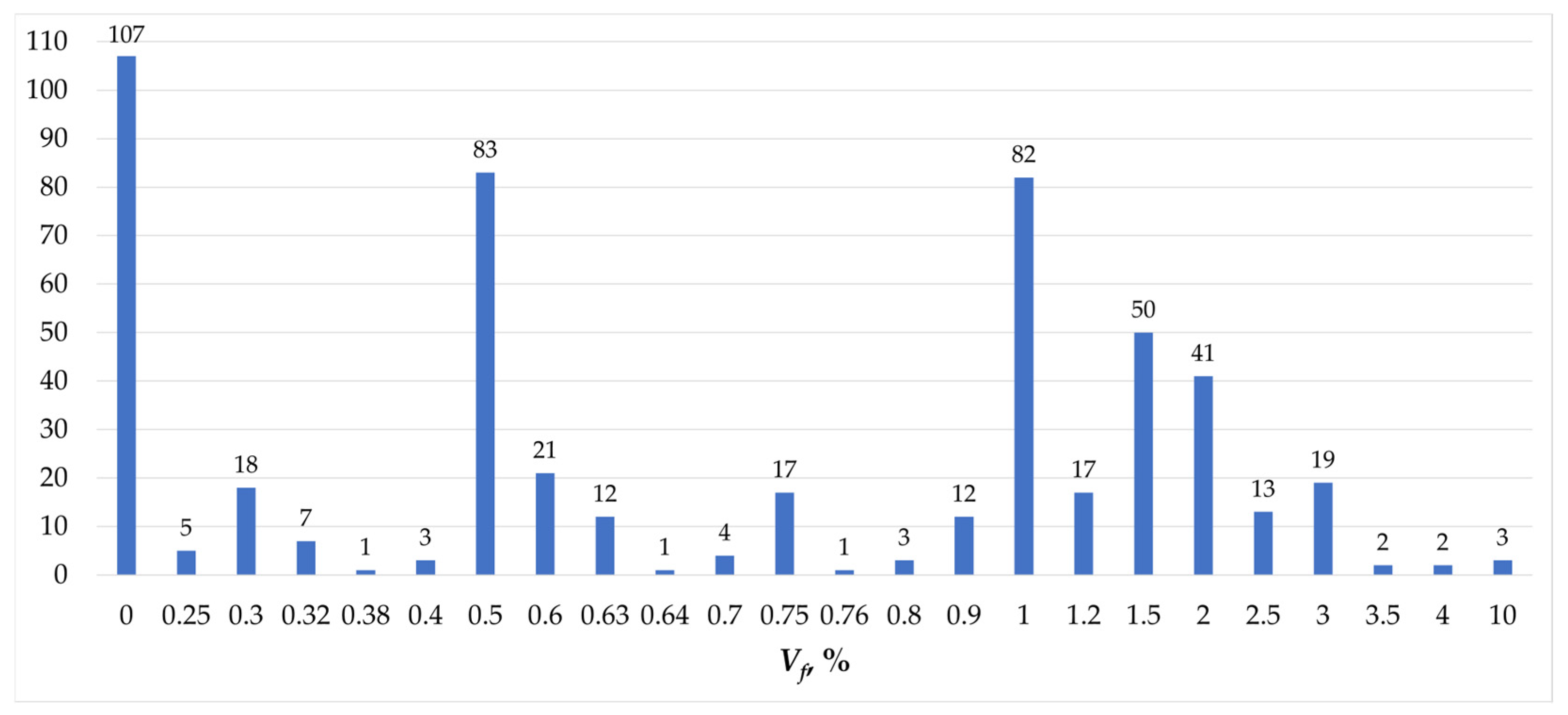
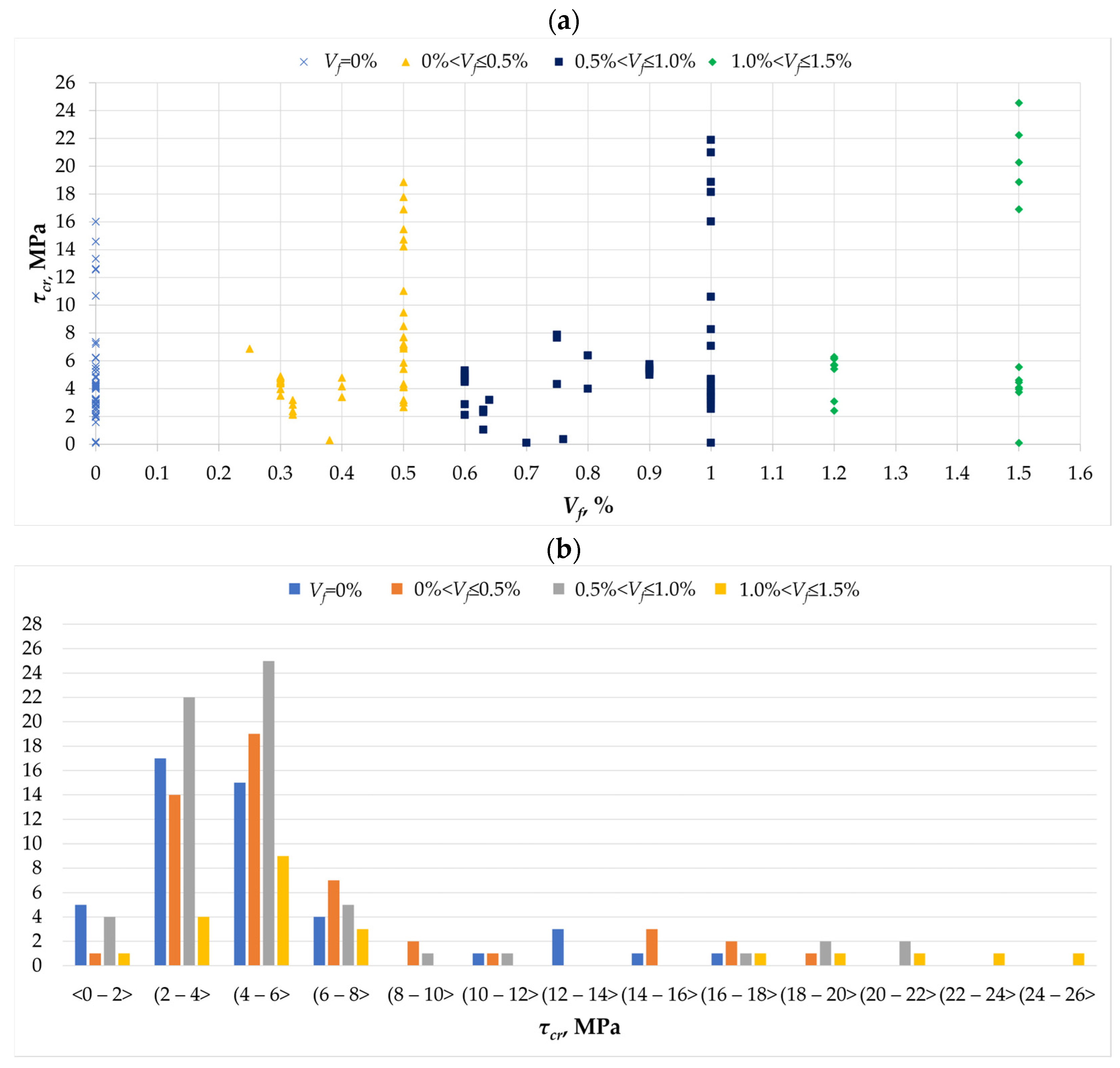
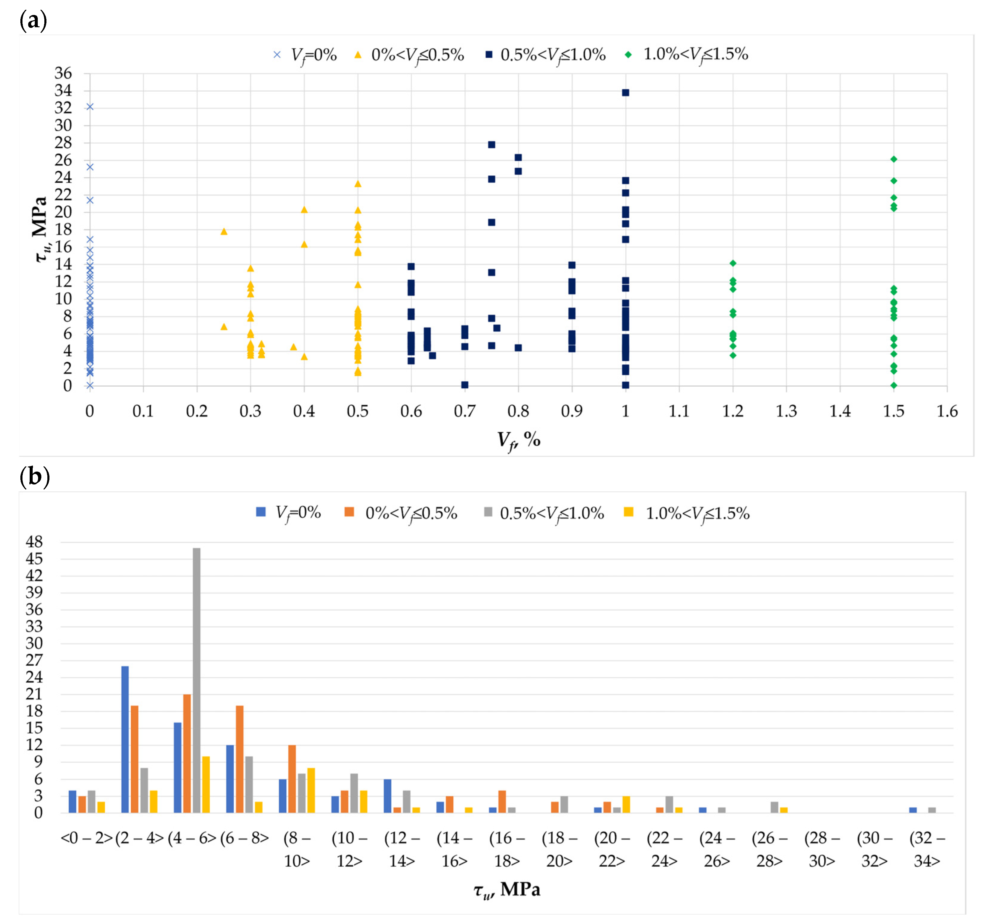

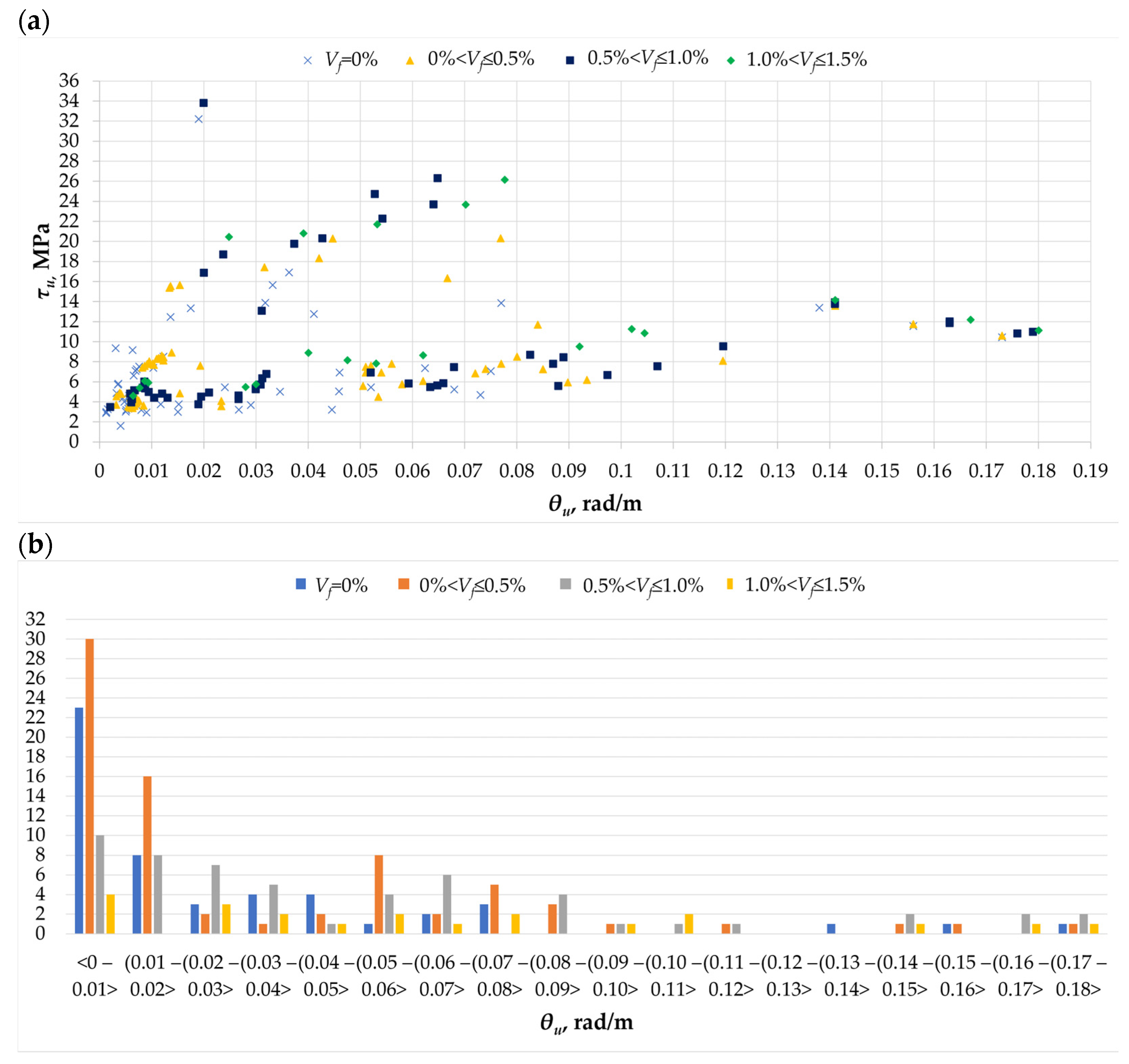

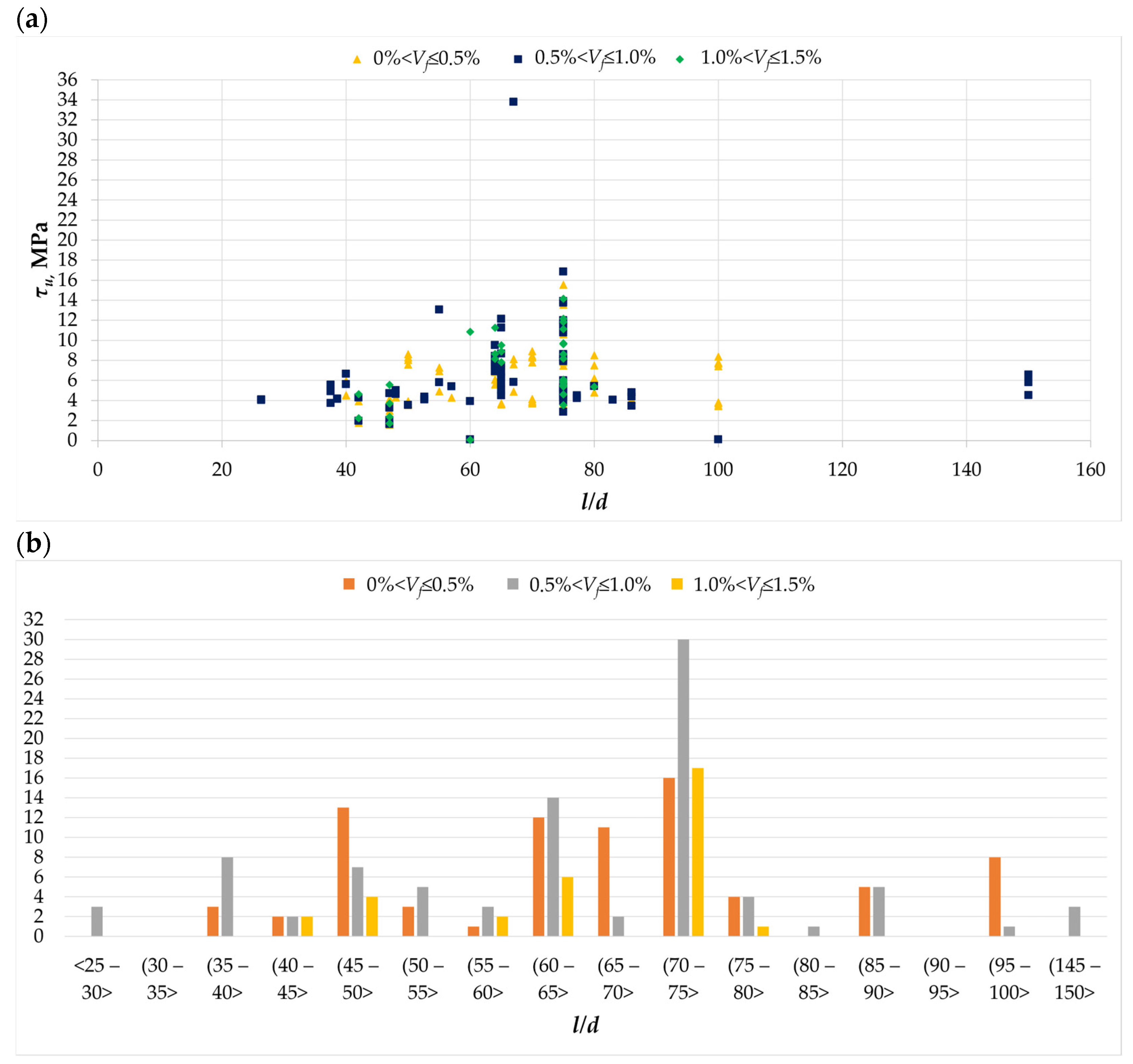
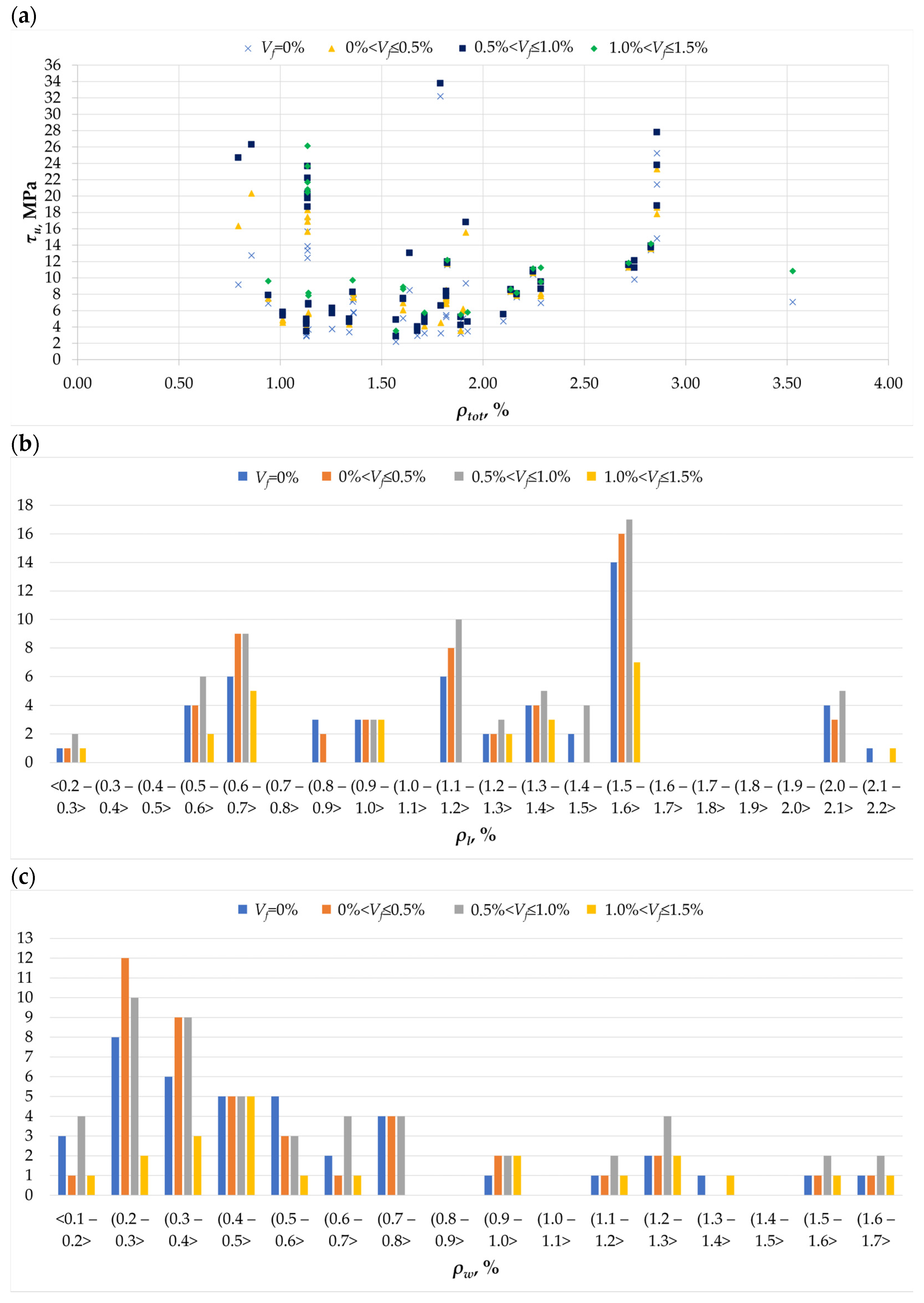
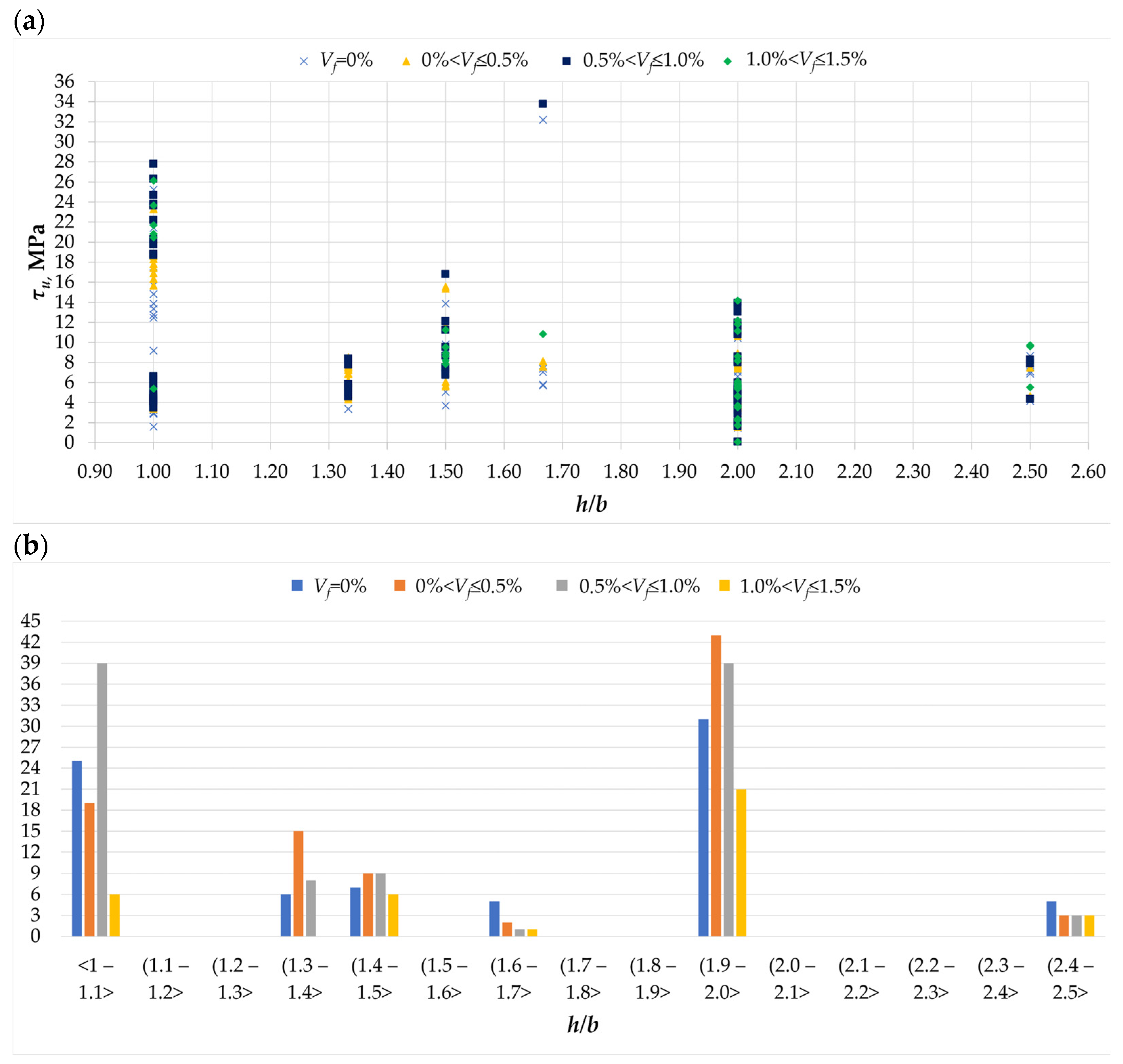
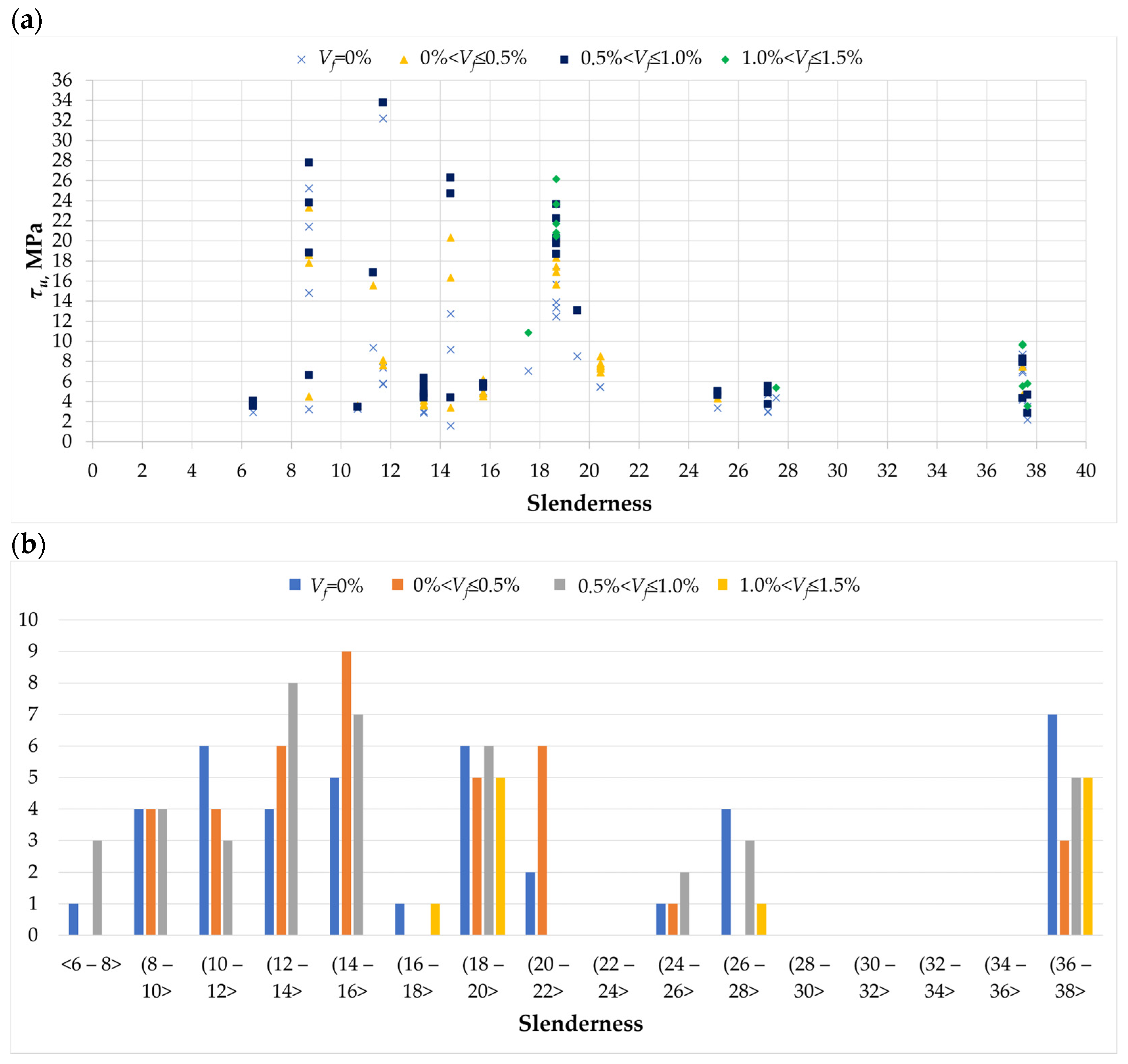

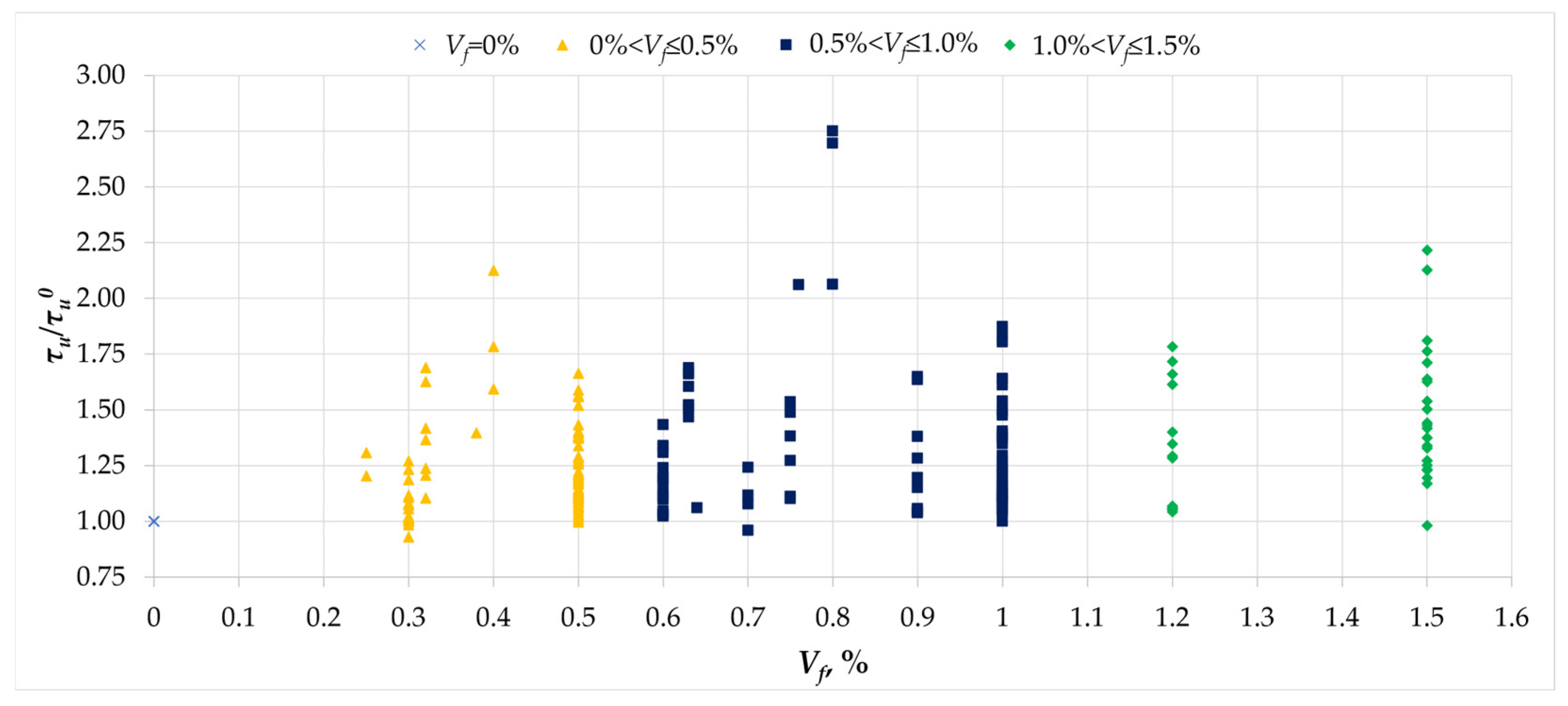
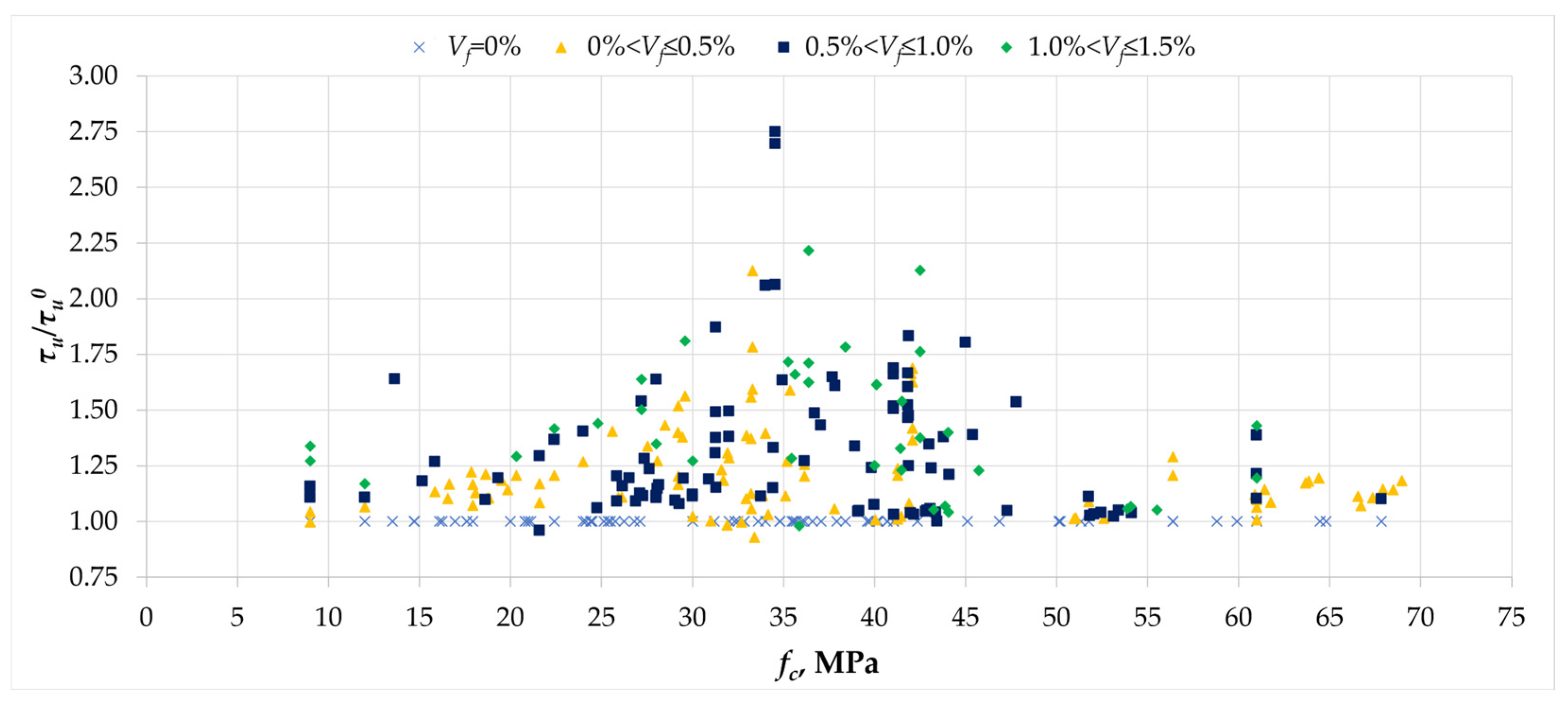
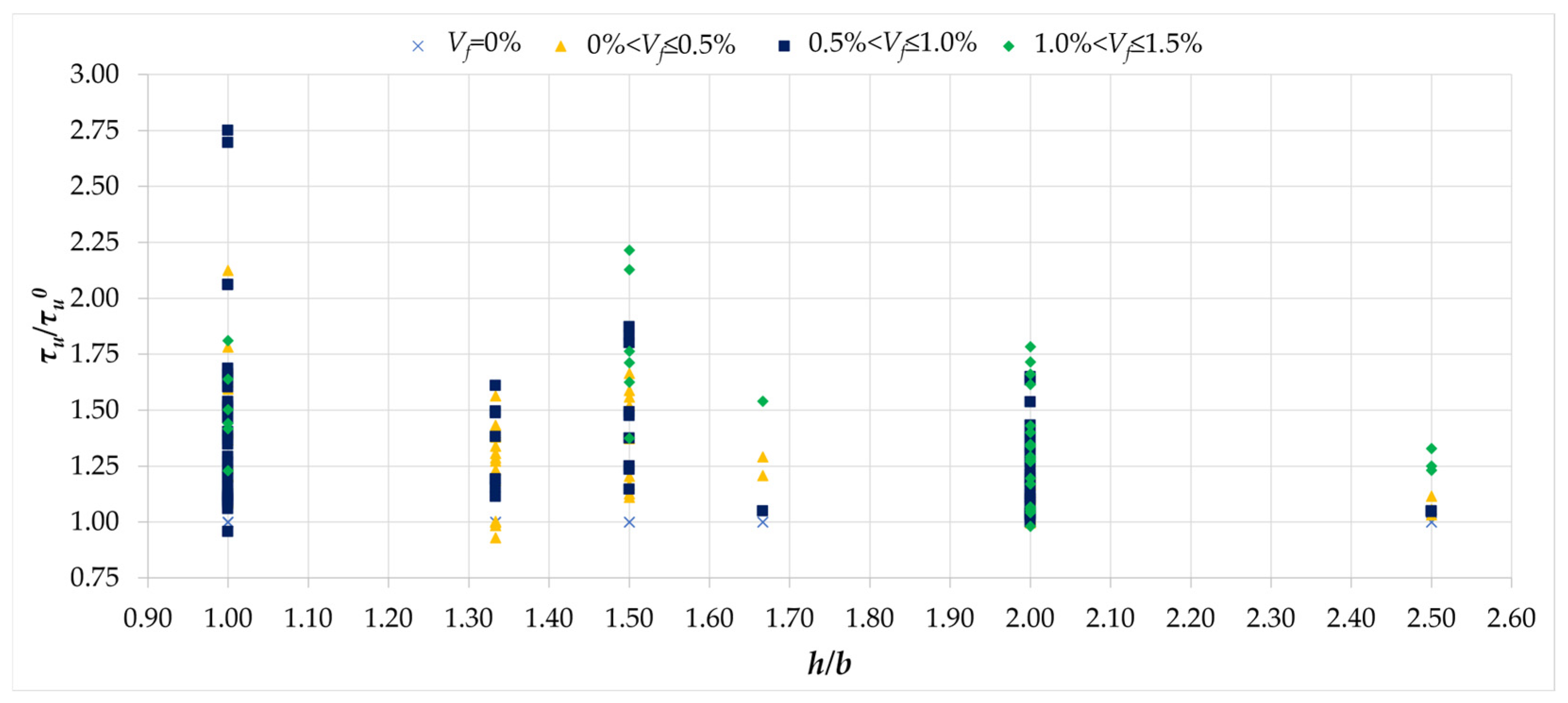
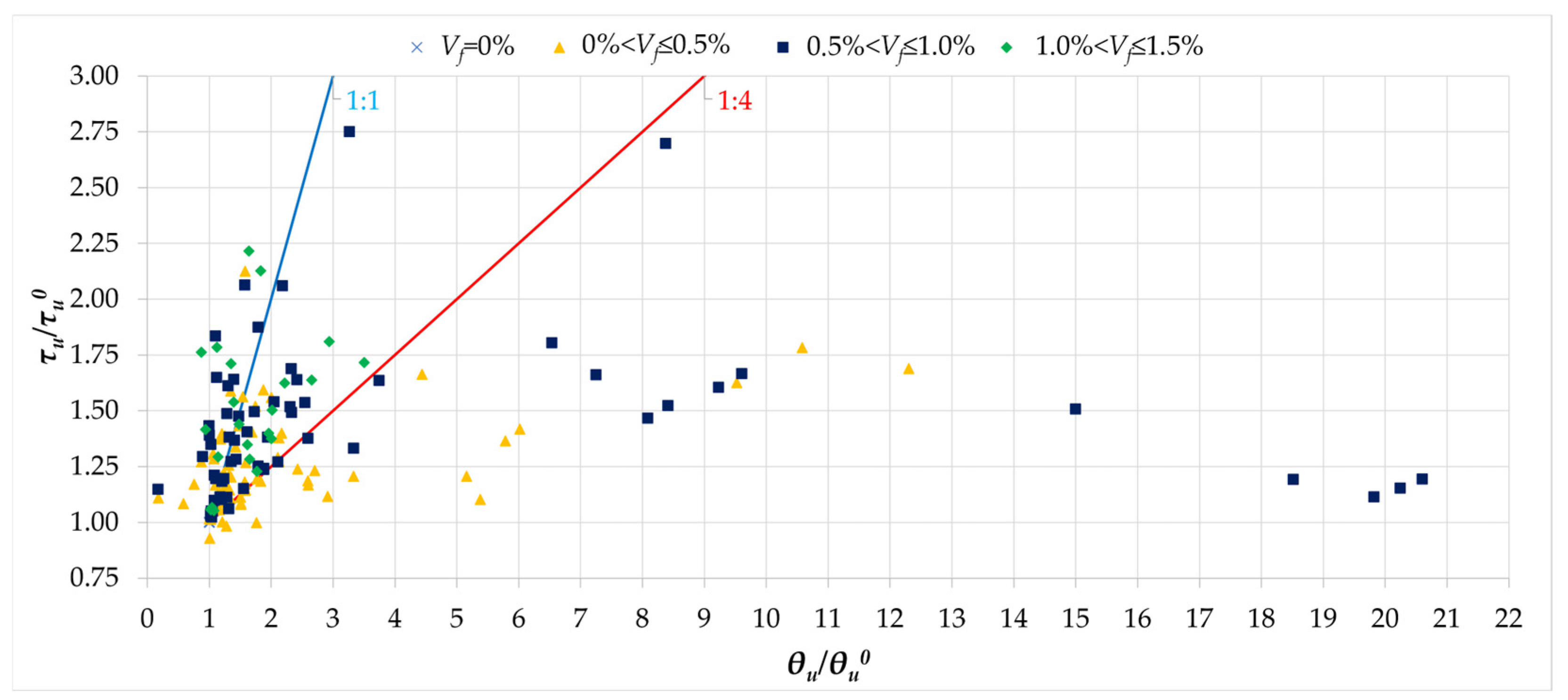
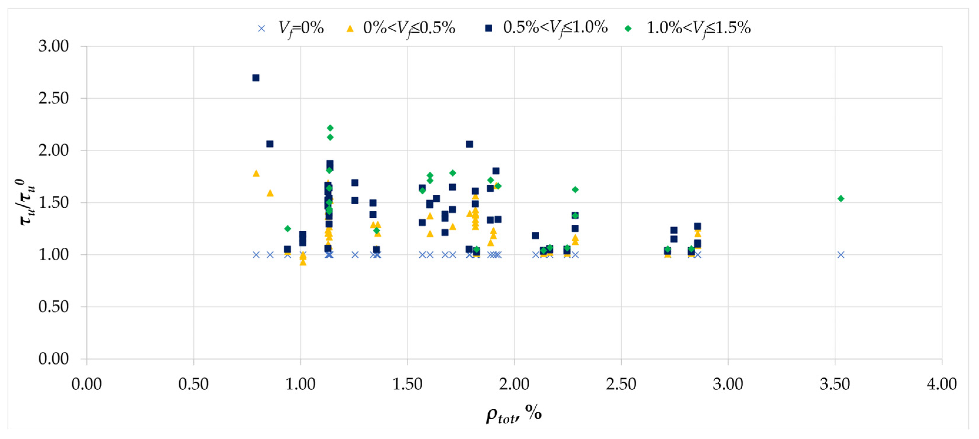
Disclaimer/Publisher’s Note: The statements, opinions and data contained in all publications are solely those of the individual author(s) and contributor(s) and not of MDPI and/or the editor(s). MDPI and/or the editor(s) disclaim responsibility for any injury to people or property resulting from any ideas, methods, instructions or products referred to in the content. |
© 2025 by the authors. Licensee MDPI, Basel, Switzerland. This article is an open access article distributed under the terms and conditions of the Creative Commons Attribution (CC BY) license (https://creativecommons.org/licenses/by/4.0/).
Share and Cite
Domski, J.; Lehmann, M.; Sanok, A.; Tvrda, K. Overview of Torsion Tests on Fiber-Reinforced Concrete Beams. Materials 2025, 18, 2452. https://doi.org/10.3390/ma18112452
Domski J, Lehmann M, Sanok A, Tvrda K. Overview of Torsion Tests on Fiber-Reinforced Concrete Beams. Materials. 2025; 18(11):2452. https://doi.org/10.3390/ma18112452
Chicago/Turabian StyleDomski, Jacek, Marek Lehmann, Artur Sanok, and Katarina Tvrda. 2025. "Overview of Torsion Tests on Fiber-Reinforced Concrete Beams" Materials 18, no. 11: 2452. https://doi.org/10.3390/ma18112452
APA StyleDomski, J., Lehmann, M., Sanok, A., & Tvrda, K. (2025). Overview of Torsion Tests on Fiber-Reinforced Concrete Beams. Materials, 18(11), 2452. https://doi.org/10.3390/ma18112452