Abstract
Iron core loss (Pcm) is the main source of energy dissipation in motors, primarily affected by the stator material, which necessitates the optimization of soft-magnetic materials. In this work, the magnetic characteristics of FeSiB amorphous alloys and their influence on motors were systematically investigated via both experiment and finite-element simulation. It was found that the Pcm of the FeSiB core initially decreased significantly during heating but subsequently increased with a further temperature rise. In particular, after annealing at 460 °C for 10 min, the FeSiB core exhibited the lowest Pcm of 0.11 W/kg (50 Hz, 1 T) and 5.45 W/kg (1 kHz, 1 T), which correlated well with the changes in the magnetization. With the help of the finite-element analysis, the low Pcm of the motor using the FeSiB core was further demonstrated, and was closely associated with the dominance of the stator loss. Additionally, the magnetic flux density cloud and the related electromagnetic torque of the motor were comparatively analyzed to unveil the potential advantages of the current FeSiB core. This work provides an important theoretical basis for the design and development of amorphous/nanocrystalline motors.
1. Introduction
Under the background of the carbon emissions peak and carbon neutrality, the energy crisis and the continued growth of electrical power generation need to minimize their wasteful energy dissipation and maximize the conversion efficiency of the electronic power devices that are used [1,2,3]. As the largest consumer of electricity, the motor has become one of the key aspects of national energy conservation and emission reduction work, with its energy dissipation mainly originating from iron core loss (Pcm) [3]. The soft-magnetic iron core is one of the key factors that determine the loss and efficiency of the motor [4,5]. Currently, electrical steels, mainly composed of iron (Fe) with less than 6.5 wt.% silicon (Si), remain the predominant materials used in applications such as transformers and motors owing to their relatively low cost and high saturation magnetization (1.8–2.0 T). However, electrical steels are hindered by high-frequency core loss caused by their inherently low electrical resistivity (48–82 µΩ·cm) [6,7]. Inversely, Fe-based amorphous soft-magnetic alloys, rendering tremendous interest, have become the focus of academia and industry due to their wide range of applications in motors and transformers by virtue of their low loss characteristics at high frequencies [8,9,10]. Sun et al. reported the influence of stators made of different magnetic materials on the efficiency of a high-speed asynchronous motor and found that the Pcm can be significantly reduced by 91.1% using a stator made of an FeSiB amorphous alloy in 0–800 Hz [11]. Liu et al. studied the magnetic field distribution, stator core loss, and efficiency of two motors and demonstrated that amorphous material improved the electromagnetic performance of low-speed motors, and also exhibited higher efficiency than that of a silicon steel motor with an increasing frequency [5]. Gao et al. verified that by replacing the silicon steel stator with the amorphous metal stator and improving the motor design, the efficiency of the motor can be increased by 4.76%, and the weight can be reduced by 11.36% [12]. Although extensive studies about motors using soft-magnetic amorphous alloys have been reported [13,14,15,16], the performance and process optimization of amorphous magnetic cores, as well as their compatibility with motor design, are still a long-term issue that needs to be explored urgently.
In this work, a typical FeSiB amorphous alloy and silicon steel as the stator materials were selected for comparison, and the influences of the stator material on the magnetic characteristics including core loss, magnetic flux density, and electromagnetic torque were systematically investigated via experiment and finite-element simulation.
2. Materials and Methods
Commercially available amorphous ribbons with a nominal composition of Fe80Si9B11 (at.%) were purchased from Jiangsu Guoneng Alloy Technology Co., Ltd. Jiangsu, China. The purity of the raw materials, including iron (Fe), silicon (Si), and boron (B), was 99.9 wt%. As-spun ribbons with widths of approximately 15 mm and thicknesses of approximately 28 μm were produced using the single roller melt-spinning method, which were then wound into round cores with an outer diameter of 28 mm, an inner diameter of 20 mm, and a height of 15 mm. Heat treatment was performed by keeping the ribbons or iron cores in a quartz tube under a vacuum atmosphere (10−3 Pa), and then pushing the quartz tube into a tubular furnace preheated to annealing temperature (420–480 °C) for various lengths of time, followed by water quenching cooling.
The microstructures of the air-sides of specimens were verified by X-ray diffraction (XRD, Bruker D8 Discover, Bruker AXS, Karlsruhe, Germany) with Cu Kα radiation and transmission electron microscopy (TEM; Talos F200X, FEI, Hillsboro, OR, USA). Here, for the XRD test, the scanning angle range is 20–90°, and the step size is 0.02°. Thermal behaviors were confirmed by differential scanning calorimeter (DSC, NETZSCH 404 C, Netzsch, Selb, Germany) with a heating rate of 0.33 °C/s under high-purity Ar protection. Similar to the previous works [17,18], the as-quenched ribbons were cut into 6 mm and then isothermally annealed in the vacuum chamber (10−3 Pa) to prepare the annealed ribbons. The magnetic properties of ribbons including B-H curves, maximum magnetic flux density (Bs), and coercivity (Hc) can be obtained by a vibrating sample magnetometer (VSM, EZ7, MicroSense, Lowell, MA, USA) under an applied field of 800 kA/m and a B-H loop tracer (BHS-40, RIKEN Machinery, Tokyo, Japan) under a field of 1 kA/m in DC mode, respectively. Moreover, the core loss and magnetization curves of the wound cores were measured via a silicon steel measuring instrument (MATS-3000M, Ningbo Economic and Technological Development Zone Kainuo Instrument Co., Ltd., Jinan, China) and soft-magnetic AC measuring device (MATS-2010SD, Lianzhong Technology Co., Ltd., Beijing, China), respectively. The electrical resistance was measured using a conventional DC four-probe method (SZJG ST2742B, Suzhou Jingge Electronics Co., Ltd., Suzhou, China). The finite-element simulation on the electromagnetic properties of motors using different soft-magnetic materials as stator components was carried out using ANSYS Maxwell software (ANSYS Electronics 2019 R3).
3. Results and Discussion
3.1. Microstructure and Thermal Behavior
Figure 1a shows the XRD patterns of the FeSiB amorphous alloys which are subjected to annealing for 10 min at different temperatures, corresponding to the temperatures just below the first exothermic peak in the DSC curve (shown in the inset in Figure 1a). With the temperature rising, a slightly sharp peak on a broad diffuse diffraction peak in the vicinity of 45° can be detected. Some works have elucidated that this change is assigned to the (110)-reflection of α-Fe crystalline phase and/or the formation of the clusters of crystal nuclei [19,20,21], which favors the optimized magnetic softness of the post-annealed alloys. It should be noted that this is different from the annealing temperature and time, which are 653 K and 60 min in Fe80Si9B11 [22]; the annealing temperature in the current work is relatively high for probing into the microstructure evolution. Furthermore, the microstructure of the present FeSiB alloy subjected to annealing at 460 °C for 10 min was illustrated using the TEM test, as shown in Figure 1b. A small number of nanocrystals can be identified on the amorphous matrix, revealing a slight crystallization, which coincides well with the XRD results. From the selected area electron diffraction pattern in the inset (top), there exist some bright dots in the diffraction ring. This is the typical characteristic of the (110)-reflection of α-Fe nanocrystals [23]. The local enlarged HRTEM image is given, as also shown in the inset (bottom). Some heterogeneous regions (crystal-like ordered clusters) are observed. These heterogeneities may act as the heterogeneous sites of α-Fe nanocrystals for the alloy during the post-annealing. Such amorphous nanocrystals and their transitional microstructures endow the alloy with potentially excellent magnetic properties.
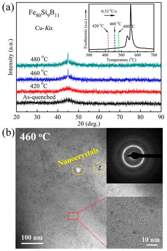
Figure 1.
(a) XRD patterns of the Fe80Si9B11 amorphous ribbons annealed at different times for 10 min. The inset is the DSC curve of the as-quenched alloy. (b) TEM image of the Fe80Si9B11 alloy subjected to annealing at 460 °C for 10 min. The inset (top) shows the selected area electron diffraction (SAED) pattern, and the (bottom) shows this in relation to the local enlarged image.
3.2. Magnetization
Figure 2 exhibits the magnetic softness of an example alloy after annealing at 420 °C for different annealing times. One can see that the lower Bs (172 Am2/kg) and larger Hc (0.91 A/m) in the as-quenched state are obtained, which is very close to the Bs of 1.56 T reported by the amorphous ribbon manufacturer [24]. With the annealing time increasing, the Hc drops to 0.67 A/m (10 min) and then increases, while Bs increases continuously, implying structural changes in the alloy after a shorter annealing time at a higher temperature. Based on this, the magnetic responses of the wound amorphous cores after annealing at different temperatures were analyzed, as shown in Figure 3. A regular magnetization curve for each amorphous core can be found, and the magnetization quickly saturates at a low applied field, implying good permeability and magnetic softness. The difference is that the amorphous core after annealing at 460 °C exhibits a quicker magnetization process and possesses a larger Bs of 1.54 T than that of 1.49 and 1.47 T at 420 °C and 480 °C, respectively, meaning a fast magnetic response of the present soft-magnetic material, which matches well with the fast start of the motor and other magnetic electronic devices [1,16]. Moreover, the inset in Figure 3 displays the changes in the electrical resistivity (ρe) of annealed amorphous cores. One can see that the ρe of cores initially increased and then decreased, and the maximum value of ρe is measured to be 130 μΩ·cm at 420 °C.
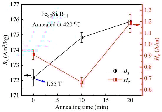
Figure 2.
Variations of Bs and Hc with respect to the annealing time for Fe80Si9B11 amorphous ribbons after annealing at 420 °C.
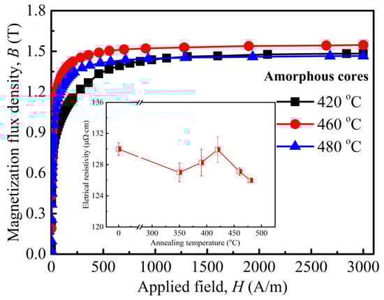
Figure 3.
Compared magnetization curves of amorphous cores annealed at various temperatures for 10 min. The inset shows the electrical resistivity changes.
3.3. Amorphous Core Loss
Furthermore, according to the lower ρe of the annealed amorphous core at 420 °C, the comparative Pcm of the amorphous cores annealed at 420 °C for various times is shown in Figure 4. It can be clearly seen that the Pcm displays a similar trend at the different frequencies, which declines compared to the as-quenched state but seems to be equal for 10 and 20 min. Moreover, similar to the phenomenon in other amorphous cores, the Pcm manifests a strong dependence on frequency (f) and Bm. According to the classical loss separation model, the total iron loss can be described as follows [11,12,25]:
where, Physt, Pec, and Pr are hysteresis loss, eddy current loss, and residual loss, and kh, ke, and kex correspond to the coefficients of hysteresis, eddy current, and residual loss, respectively. It is apparent that each loss component exhibits a different sub-exponential relationship with frequency (f) and Bs, but both support an increase in Pcm. Apart from f and Bs, the Hc and resistivity (ρe) should be highlighted. For instance, the Physt is BsHc [26]; Pec [27]; and Pr [8]. It can be clearly seen that compared to the as-quenched amorphous core, the annealed ones at 10 and 20 min show a lower Pcm, especially at 20 min, implying the influence of microstructural changes in amorphous cores after annealing relaxation on Pcm. As a result, taking into account the magnetization and ρe features, the 420 °C and 10 min were determined as the optimal parameters for the further exploration of the annealing process.
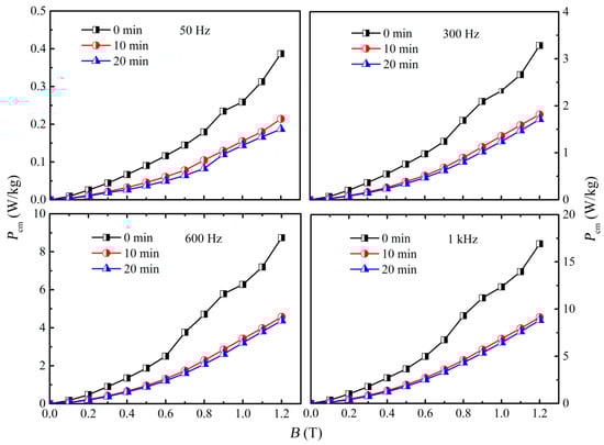
Figure 4.
Dependence of loss in amorphous cores annealed at 420 °C on annealing time at various frequencies.
To gain a deeper understanding of the correlation between Pcm and structural changes, the Pcm of amorphous cores after annealing at various temperatures is investigated, with the results shown in Figure 5. One can see that at both 50 Hz and 1 kHz, Pcm significantly drops as the annealing temperature increases from 350 °C to 460 °C, and then increases at 480 °C; similar trends are evident in Figure 5a,b. The comparative Pcm at 1 and 1.2 T as a function of the temperature is further extracted, as shown in Figure 5c,d. The Pcm declines first and then increases as the temperature rises. In particular, at 460 °C, the lower Pcm values of 0.11 W/kg at 50 Hz and 5.45 W/kg at 1 kHz are recorded at a magnetic field of 1 T. When the magnetic field is increased to 1.2 T, the Pcm increases to 0.16 W/kg at 50 Hz and 7.54 W/kg at 1 kHz under the same conditions. These values are still at the minimum across all temperature ranges, indicating the optimal microstructure at the current annealing temperature for amorphous cores.
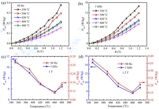
Figure 5.
(a,b) loss of the amorphous core annealed at various temperatures as a function of the magnetic induction at 50 Hz and 1 kHz, respectively; (c,d) changes in the loss dependence on the various temperatures under an applied field of 1 T and 1.2 T, respectively.
Next, the dependence of Pcm on magnetic flux density B for the current work (highlighted by the larger symbols in green, red, and blue) is compared with that of other FeB-based amorphous and Fe-Si crystalline alloys, as reported in references [15,25,28,29,30,31,32,33,34], and is shown in Figure 6. The figure on the right is a locally enlarged image for the rectangle dotted line area in the left figure. As can be seen, the Pcm of the displayed Fe-based amorphous alloys is much lower than that of the Fe-Si alloy, unveiling the unique magnetic properties and great application advantages of the former. Particularly, compared with the previous reports, the Pcm in the current work appears to be the lowest value at the same f and B, manifesting a better heat treatment process.
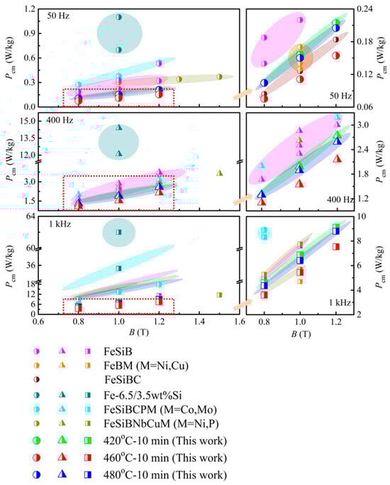
Figure 6.
Relationship between core loss and magnetic flux density of cores wound by present alloys and some other reported amorphous alloys at different frequencies.
3.4. Finite-Element Simulation
To accurately represent the real-time performance of the present amorphous cores as a stator component, the finite-element simulation model was utilized to analyze the loss, magnetic flux density distribution, torque, and efficiency of the motor during operation. In this work, a permanent magnet synchronous motor with a rated power of 750 W is employed, and the motor model is designed in Figure 7, which mainly involves four parts: rotor core, permanent magnet (PM), coil, and stator core. The detailed parameters are outlined in Table 1.
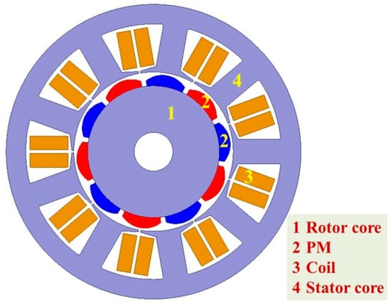
Figure 7.
Motor construction diagram.

Table 1.
Main parameters of motor model.
Figure 8 exhibits the core loss distribution of a simulated motor operating at a rated speed of 3000 rpm. Also, the data of a typical silicon steel (SS, 50WW270) are shown for comparison. As shown in Figure 8a, the current amorphous core exhibits significantly lower core loss, approximately 1/10 to 1/14 of SS, which is crucial for power electronic devices and represents a distinctive advantage that is not observed in other soft-magnetic materials. This result is also consistent with the previous works reported in FeSiBC, FeSiBPCu, and FeSiBNbCu amorphous/nanocrystalline alloys, where the core loss is 1/2 to 1/5 smaller than that of Fe-Si alloy [3,35]. Moreover, the tiny difference in loss spectra for the present annealed alloys can be discerned, where the lowest loss for the amorphous core annealed at 460 °C is confirmed. This is in accordance with the above result in Figure 5. In addition, the loss of the separate stator and rotor are extracted from the total loss spectra, as shown in Figure 8b,c. It can be observed that the stator loss shows the same tendency and values as the total loss, while the rotor loss is significantly lower, being only approximately 1/200 of the total loss, and thus can be considered negligible in the current motor design. This unveils the dominance of stator losses in the overall loss profile and further implies the importance of designing soft-magnetic materials tailored to the stator in motor design. It is noted that the larger fluctuations in the loss of SS after stable operation can likely be attributed to the rapid increase in loss with the magnetization increase. However, when subjected to the minor influence of the present loss on magnetization, it manifests a small fluctuation. All of the above further confirm the superiority of the current soft-magnetic material for the stator design.
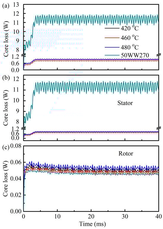
Figure 8.
Core loss variations during motor operation: (a) total loss, (b) loss of stator, (c) loss of rotor.
To comprehend the magnetic response of the amorphous/nanocrystalline cores required for the stator in a motor, the magnetic flux density cloud of the motor using different soft-magnetic alloys under rated operating conditions is analyzed. Here, the amorphous core annealed at 460 °C and SS are comparatively given in Figure 9, with the motor running times being 5 and 30 ms. As shown in Figure 9a,b, when the motor initially starts and runs for 5 ms, the magnetic flux density is mainly concentrated at the tip of the teeth (red regions), while other areas such as the yoke are less dense, a fact widely accepted in the literature [11,14]. The current of the motor during startup is approximately 4–7 times that of the rated current. The magnetic motive force generated by the stator winding is directly proportional to the current passing through it. Thus, the enhancement of the magnetic motive force leads to a highly saturated state of the amorphous core part of the leakage magnetic circuit. This may be one of the reasons for the high loss of the motor when it first starts. After running for 30 ms, as shown in Figure 9c,d, the magnetic flux density in the vicinity of the tip of the teeth seems to be strengthening, while in the yoke, the phenomenon of supersaturation has not yet been observed, indicating a good operating state. Furthermore, three random locations (m1, m2, and m3) on the yoke of the motor are marked to analyze the magnetic flux density distribution. After running, the locations of m4, m5, and m6 correspond to m1, m2, and m3, respectively, and the corresponding magnetic flux density is listed in Table 2. A slight difference at the marked points is observed. As the motor starts running (5 ms), the magnetic flux density at these points first increases and then decreases, and the maximum values of Bs are achieved at 460 °C, being the closest to that of the SS motor. This trend is similar to the one observed at 30 ms, indicating that both the amorphous motor at the current temperature and the SS motor exhibit a faster rate of field establishment, which suggests an improved response speed of the motor. To further evaluate the stability of the motor operation, the electromagnetic torque and its fluctuations are studied, as shown in Figure 10. When the motor runs stably, the present amorphous core annealed at 460 °C and the SS exhibit the larger electromagnetic torque in all listed cores, which are 2.16 and 2.17 N·m, respectively, indicating a greater running power and a higher speed of the motor using the present amorphous core and SS. Nevertheless, the lower torque fluctuation of 3.41% for the present amorphous core than that of 3.7% for the SS is achieved. From the stator perspective, smaller fluctuations may reduce the noise and vibration generated during motor operation, thereby improving the operational stability of the motor. All the above experimental and finite-element simulation studies reveal the importance of stator material optimization and provide a theoretical basis for the design and development of amorphous/nanocrystalline motors.

Figure 9.
Magnetic density cloud of the motor using different soft-magnetic alloys for different running times at the rated operating conditions: (a,c) iron core annealed at 460 °C for 5 ms and 30 ms, respectively; (b,d) SS (50WW270) for 5 ms and 30 ms, respectively.
Table 2.
The magnetic flux density of the different stators after operating for different times.
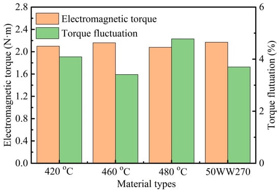
Figure 10.
Electromagnetic torque and its fluctuation of motor using different soft-magnetic materials.
4. Conclusions
In this work, the magnetic characteristics of FeSiB amorphous alloys and their influence on motors were systematically investigated via both experiment and finite-element simulation. The main results are summarized as follows.
- (1)
- The FeSiB amorphous core annealed at 460 °C for 10 min exhibits a high magnetic flux density of 1.54 T and low core loss of 0.11 W/kg at 50 Hz and 5.45 W/kg at 1 kHz at 1 T. These values are essential for ensuring high magnetic response and energy efficiency in motors and other electronic devices.
- (2)
- Finite-element simulation analysis reveals that the reduced core loss in the FeSiB motor, compared to the 50WW270 silicon steel motor, is primarily attributable to the stator loss, which in turn is ultimately governed by the microstructure and magnetic properties of the soft-magnetic material.
- (3)
- Both amorphous alloy and silicon steel materials contribute to enhanced motor response speed. The current amorphous motor demonstrates stable electromagnetic torque (2.16 N·m) with reduced torque fluctuation (3.41%), resulting in decreased noise and vibration during motor operation, which improves the motor’s operational stability.
Author Contributions
Methodology, H.L. and L.L.; Software, L.H.; Validation, W.J.; Formal analysis, Y.M.; Resources, Writing—original draft, Z.G.; Investigation, W.Y.; Data curation, M.W. and D.M. All authors have read and agreed to the published version of the manuscript.
Funding
This work was supported by the Key Research & Development plan of Anhui Province (Grant No. 2022a05020016), the University Natural Science Research Project of Anhui Province (Grant No. 2023AH051084), and the Open Project of International Joint Research Center for Terahertz Device Research and Application (Grant No. 2024GH03001).
Institutional Review Board Statement
Not applicable.
Informed Consent Statement
Not applicable.
Data Availability Statement
The original contributions presented in this study are included in the article. Further inquiries can be directed to the corresponding authors.
Conflicts of Interest
The authors declare no conflicts of interest.
References
- Bottauscio, O. Soft Magnetic Materials 21 Publication Chair’s Preface. In Proceedings of the Selected Papers from the 21st Soft Magnetic Materials Conference (SMM 21), Budapest, Hungary, 1–4 September 2013. [Google Scholar]
- McHenry, M.E.; Willard, M.A.; Laughlin, D.E. Amorphous and nanocrystalline materials for applications as soft magnets. Prog. Mater. Sci. 1999, 44, 291–433. [Google Scholar] [CrossRef]
- Makino, A.; Kubota, T.; Yubuta, K.; Inoue, A.; Urata, A.; Matsumoto, H.; Yoshida, S. Low core losses and magnetic properties of Fe85-86Si1-2B8P4Cu1 nanocrystalline alloys with high B for power applications (invited). J. Appl. Phys. 2011, 109, 07A302. [Google Scholar] [CrossRef]
- Krings, A.; Boglietti, A.; Cavagnino, A.; Sprague, S. Soft magnetic material status and trends in electric machines. IEEE Trans. Ind. Electron. 2017, 64, 2405–2414. [Google Scholar] [CrossRef]
- Liu, R.F.; Ma, X.; Cao, J.C.; Wu, Z.G. Performance comparison of amorphous and silicon steel used in stator core of permanent magnet synchronous motors. Elect. Mach. Cont. 2020, 24, 61–68. [Google Scholar]
- Ouyang, G.; Chen, X.; Liang, Y.; Macziewski, C.; Cui, J. Review of Fe-6.5 wt%Si high silicon steel-A promising soft magnetic material for sub-kHz application. J. Magn. Magn. Mater. 2019, 481, 234–250. [Google Scholar] [CrossRef]
- Egbu, J.; Ohodnicki, P.R., Jr.; Baltrus, J.P.; Talaat, A.; Wright, R.F.; McHenry, M.E. Analysis of surface roughness and oxidation of FeNi-based metal amorphous nanocomposite alloys. J. Alloys Compd. 2022, 912, 165155. [Google Scholar] [CrossRef]
- Jiang, M.F.; Cai, M.J.; Zhou, J.; Di, S.Y.; Li, X.; Luo, Q.; Shen, B.L. Superior high-frequency performances of Fe-based soft-magnetic nanocrystalline alloys. Mater. Today Nano 2023, 22, 100307. [Google Scholar] [CrossRef]
- Zhou, J.; Li, X.S.; Hou, X.B.; Ke, H.B.; Fan, X.D.; Luan, J.H.; Peng, H.L.; Zeng, Q.S.; Lou, H.B.; Wang, J.G.; et al. Ultrahigh permeability at high frequencies via a magnetic-heterogeneous nanocrystallization mechanism in an iron-Based amorphous alloy. Adv. Mater. 2023, 35, 2304490. [Google Scholar] [CrossRef]
- Lu, S.H.; Wang, M.G.; Zhao, Z.K. Recent advances and future developments in Fe-based amorphous soft magnetic composites. J. Non-Cryst. Solids 2023, 616, 122440. [Google Scholar] [CrossRef]
- Zhu, F.; Zhang, J.H.; Wang, J.H.; Zhou, F.; Sun, H.B. Numerical simulation analysis of high-speed asynchronous motor based on Fe-based amorphous alloy and SMC stator. J. Phys. Conf. Ser. 2022, 2390, 012104. [Google Scholar] [CrossRef]
- Lai, Y.F.; Hu, X.L.; Shi, G.B.; Yu, J.T.; Wang, L.; Gao, Z.F. Loss and efficiency analysis of the brushless direct current motor with an amorphous stator core. J. Electr. Eng. Technol. 2023, 18, 2075–2085. [Google Scholar] [CrossRef]
- Fan, Z.Y.; Yi, H.; Xu, J.; Xie, K.; Qi, Y.; Ren, S.L.; Wang, H.D. Performance study and optimization design of high-speed amorphous alloy induction motor. Energies 2021, 14, 2468. [Google Scholar] [CrossRef]
- Tao, D.J.; Li, G.F.; Hou, P.; Hu, G. Analysis of load loss characteristics of FeCo alloy high speed permanent magnet motor. Machines 2022, 10, 735. [Google Scholar] [CrossRef]
- Hu, H.Y.; Wang, J.B.; Huang, S.S.; Tian, B.Z.; Wang, L.H.; Pei, R. Loss analysis of magnetization annealed amorphous alloy replacement stator teeth. AIP Adv. 2023, 13, 045101. [Google Scholar] [CrossRef]
- Li, L.J.; Lu, Z.C.; Li, Z.; Wu, X.R.; Gao, S.; Li, D.R. Magnetic characteristics of nanocrystalline alloy stator core for high speed switched reluctance motor. Elect. Mach. Cont. Appl. 2019, 46, 88–93. [Google Scholar]
- Fan, X.D.; Jiang, M.F.; Zhang, T.; Hou, L.; Wang, C.X.; Shen, B.L. Thermal, structural and soft magnetic properties of FeSiBPCCu alloys. J. Non-Cryst. Solids 2020, 533, 119941. [Google Scholar] [CrossRef]
- Hou, L.; Wang, B.J.; Liu, L.; Mao, X.H.; Zhang, M.Y.; Yuan, C.C.; Li, Z.; Ju, W.W.; Feng, H.C.; Tang, C.Y.; et al. Tailoring magnetic softness of Fe-based amorphous alloys with superior magnetization by magnetic field annealing. J. Mater. Sci. Technol. 2024, 200, 27–37. [Google Scholar] [CrossRef]
- Hou, L.; Jiang, C.; Liu, H.S.; Luo, Q.; Fan, X.D.; Li, W.H.; Li, M.R. Tunable and attractive magnetic properties of FeBPSiCu alloys. J. Alloys Compd. 2021, 859, 157863. [Google Scholar] [CrossRef]
- Li, X.S.; Zhou, J.; Shen, L.Q.; Sun, B.A.; Bai, H.Y.; Wang, W.H. Exceptionally high saturation magnetic flux density and ultralow coercivity via an amorphous-nanocrystalline transitional microstructure in an FeCo-based Alloy. Adv. Mater. 2022, 35, 2205863. [Google Scholar] [CrossRef]
- Fan, X.D.; Zhang, T.; Yang, W.M.; Luan, J.H.; Jiao, Z.B.; Li, H. Design of FeSiBPCu soft magnetic alloys with good amorphous forming ability and ultra-wide crystallization window. J. Mater. Sci. Technol. 2023, 147, 124–131. [Google Scholar] [CrossRef]
- Wang, C.X.; Wu, Z.Y.; Feng, X.M.; Li, Z.; Gu, Y.; Zhang, Y.; Tan, X.H.; Xu, H. The effects of magnetic field annealing on the magnetic properties and microstructure of Fe80Si9B11 amorphous alloys. Intermetallics 2020, 118, 106689. [Google Scholar] [CrossRef]
- Fan, X.D.; Zhang, T.; Jiang, M.F.; Yang, W.W.; Shen, B.L. Synthesis of novel FeSiBPCCu alloys with high amorphous forming ability and good soft magnetic properties. J. Non-Cryst. Solids 2019, 50, 36–43. [Google Scholar] [CrossRef]
- Yao, K.F.; Shi, L.X.; Chen, S.Q.; Yang, S.; Chen, N.; Jia, J.L. Research progress and application prospect of Fe-based soft magnetic amorphous/nanocrystalline alloys. Acta. Phys. Sin-Ch. Ed. 2018, 67, 016101. [Google Scholar]
- Lin, J.C.; Li, X.L.; Zhou, S.X.; Zhang, Q.; Li, Z.Z.; Wang, M.X.; Shi, G.B.; Wang, L.; Zhang, G.Q. Effects of heat treatment in air on soft magnetic properties of FeCoSiBPC amorphous core. J. Non-Cryst. Solids 2022, 597, 121932. [Google Scholar] [CrossRef]
- Biráková, Z.; Kollár, P.; Füzer, J.; Bureš, R.; Fáberová, M. Irreversible permeability of Fe-Based soft magnetic composites. Acta Phys. Pol. 2020, 137, 843–845. [Google Scholar] [CrossRef]
- Kollár, P.; Olekšáková, D.; Vojtek, V.; Füzer, J.; Fáberová, M.; Bureš, R. Steinmetz law for ac magnetized iron-phenolformaldehyde resin soft magnetic composites. J. Magn. Magn. Mater. 2017, 424, 245–250. [Google Scholar] [CrossRef]
- Li, D.R.; Li, S.H.; Lu, Z.C. The effects of post-processing on longitudinal magnetostriction and core losses of high saturation flux density FeSiBC amorphous alloy ribbons and cores. J. Magn. Magn. Mater. 2021, 538, 168272. [Google Scholar] [CrossRef]
- Hawelek, L.; Warski, T.; Radoń, A.; Pilsniak, A.; Maziarz, W.; Szlezynger, M.; Kadziolka-Gawel, M.; Kolano-Burian, A. Structure and magnetic properties of thermodynamically predicted rapidly quenched Fe85-xCuxB15 alloys. Materials 2021, 14, 7807. [Google Scholar] [CrossRef]
- Suzuki, K.; Parsons, R.; Zang, B.; Onodera, K.; Kishimoto, H.; Shoji, T.; Kato, A. Nano-crystallization of amorphous alloys by ultra-rapid annealing: An effective approach to magnetic softening. J. Alloys Compd. 2018, 735, 613–618. [Google Scholar] [CrossRef]
- Makino, A.; Men, H.; Kubota, T.; Yubuta, K.; Inoue, A. New Fe-metalloids based nanocrystalline alloys with high Bs of 1.9 T and excellent magnetic softness. J. Appl. Phys. 2009, 105, 07A308. [Google Scholar] [CrossRef]
- Murugaiyan, P.; Mitra, A.; Roy, R.K.; Panda, A.K. Nanocrystallization and Core-loss properties of Fe-rich FeSiBPNbCu nanocrystalline alloy. J. Magn. Magn. Mater. 2022, 552, 169228. [Google Scholar] [CrossRef]
- Fan, X.D.; Jiang, M.F.; Wang, Y.H.; Li, D.H.; Hou, L.; Yang, W.M.; Shen, B.L. Effect of Ni substitution for Si element on thermal and soft magnetic properties of Fe73.5NixSi15.5-xB7Nb3Cu1 nanocrystalline alloys. J. Electron. Mater. 2021, 50, 4577–4585. [Google Scholar] [CrossRef]
- Ouyang, G.; Macziewski, C.R.; Jensen, B.; Ma, T.; Choudhary, R.; Dennis, K.; Zhou, L.; Paudyal, D.; Anderson, I.; Kramer, M.J.; et al. Effects of solidification cooling rates on microstructures and physical properties of Fe-6.5% Si alloys. Acta Mater. 2021, 205, 116575. [Google Scholar] [CrossRef]
- Ogawa, Y.; Naoe, M.; Yoshizawa, Y.; Hasegawa, R. Magnetic properties of high Bs Fe-based amorphous material. J. Magn. Magn. Mater. 2006, 304, e675–e677. [Google Scholar] [CrossRef]
Disclaimer/Publisher’s Note: The statements, opinions and data contained in all publications are solely those of the individual author(s) and contributor(s) and not of MDPI and/or the editor(s). MDPI and/or the editor(s) disclaim responsibility for any injury to people or property resulting from any ideas, methods, instructions or products referred to in the content. |
© 2025 by the authors. Licensee MDPI, Basel, Switzerland. This article is an open access article distributed under the terms and conditions of the Creative Commons Attribution (CC BY) license (https://creativecommons.org/licenses/by/4.0/).