
Effect of Cryogenic Treatments on Hardness, Fracture Toughness, and Wear Properties of Vanadis 6 Tool Steel


Abstract
1. Introduction
2. Materials and Methods
2.1. Materials
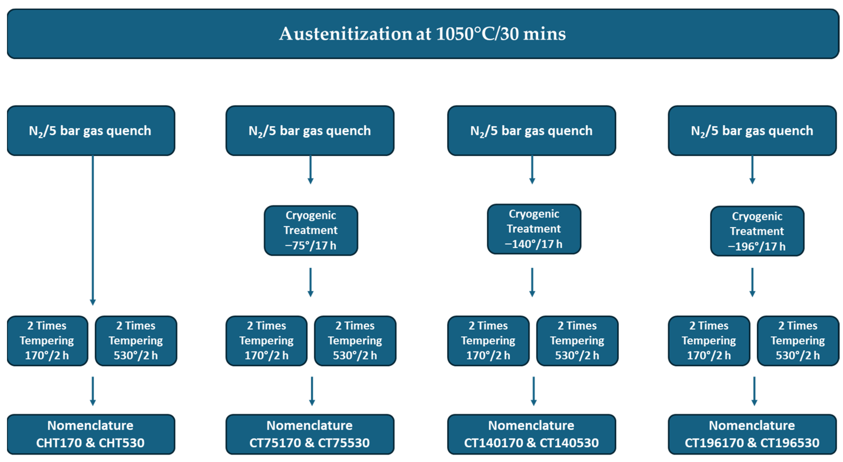
2.2. Methods
3. Results and Discussions
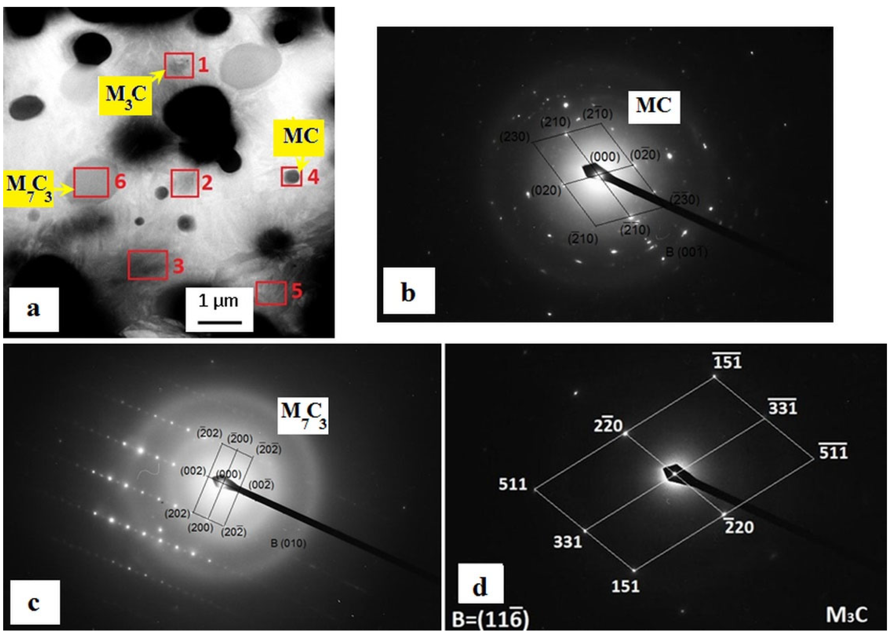
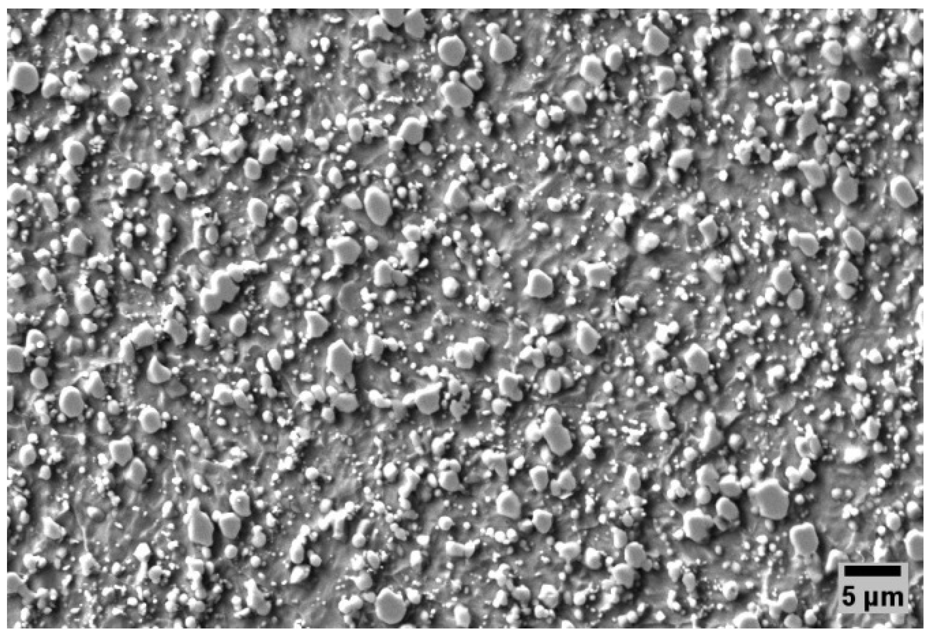
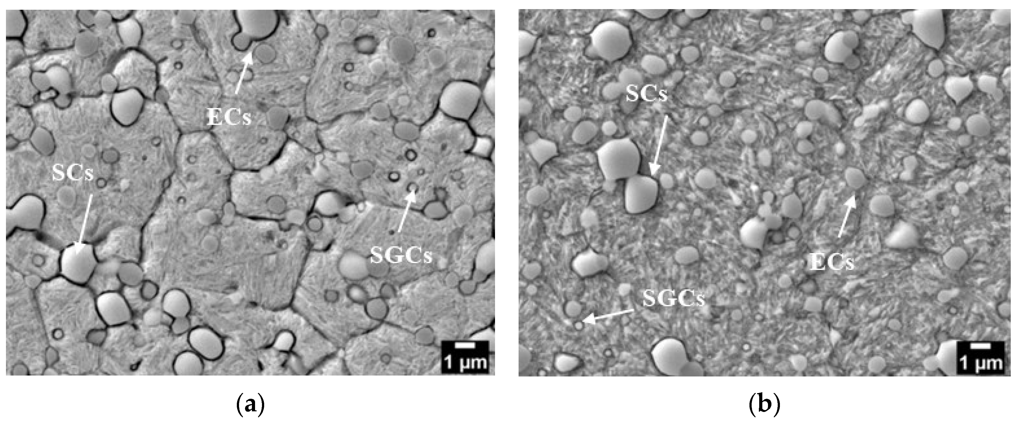
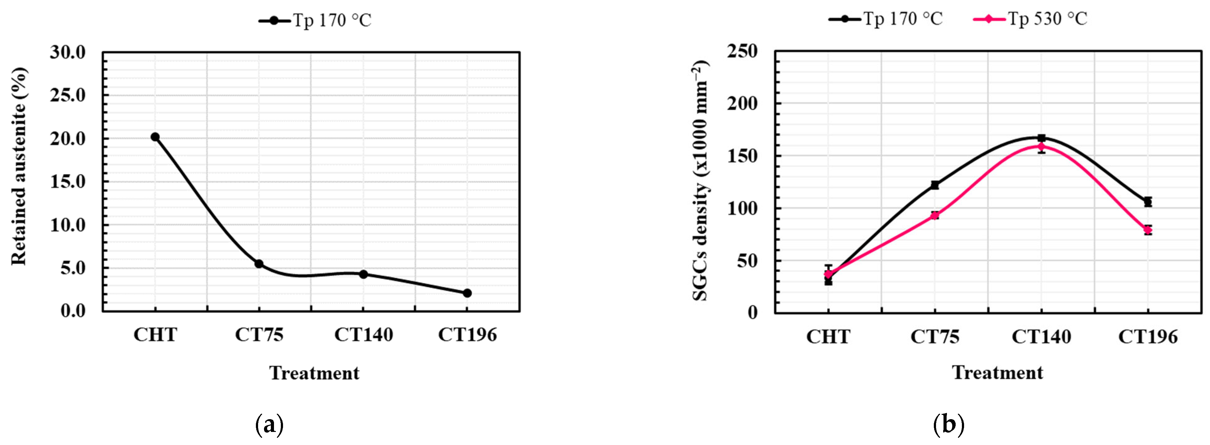
3.1. Microstructure
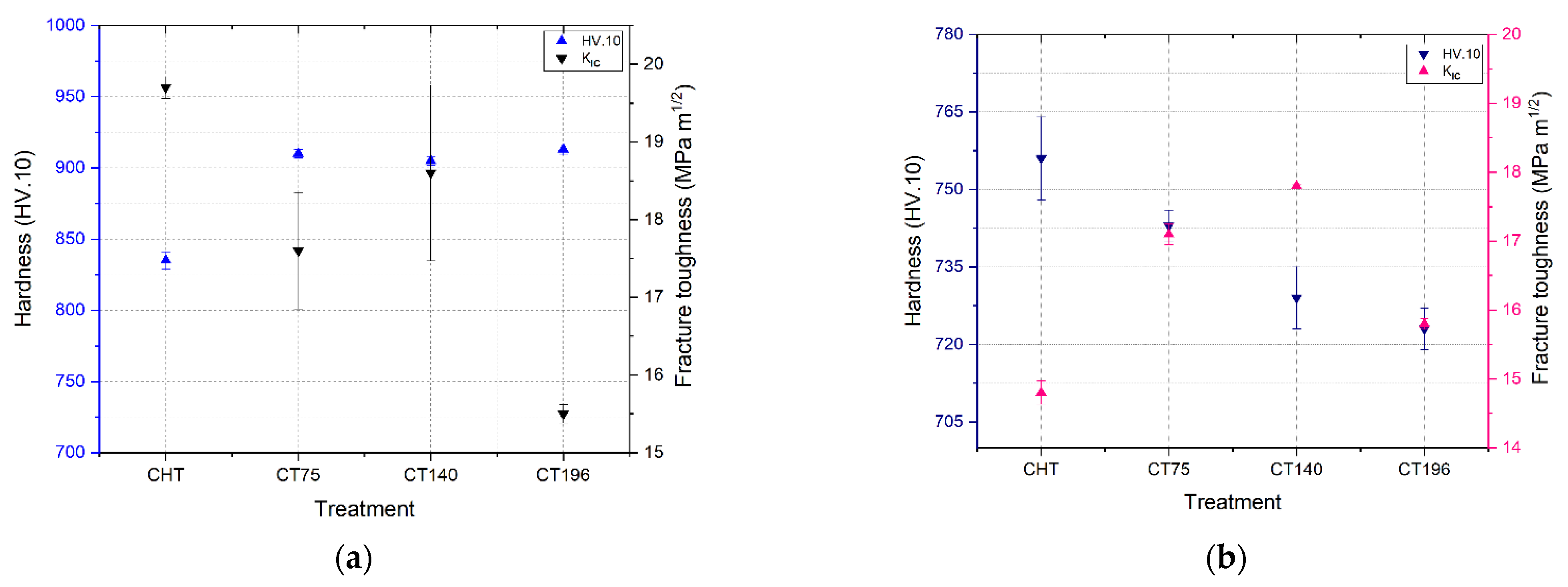
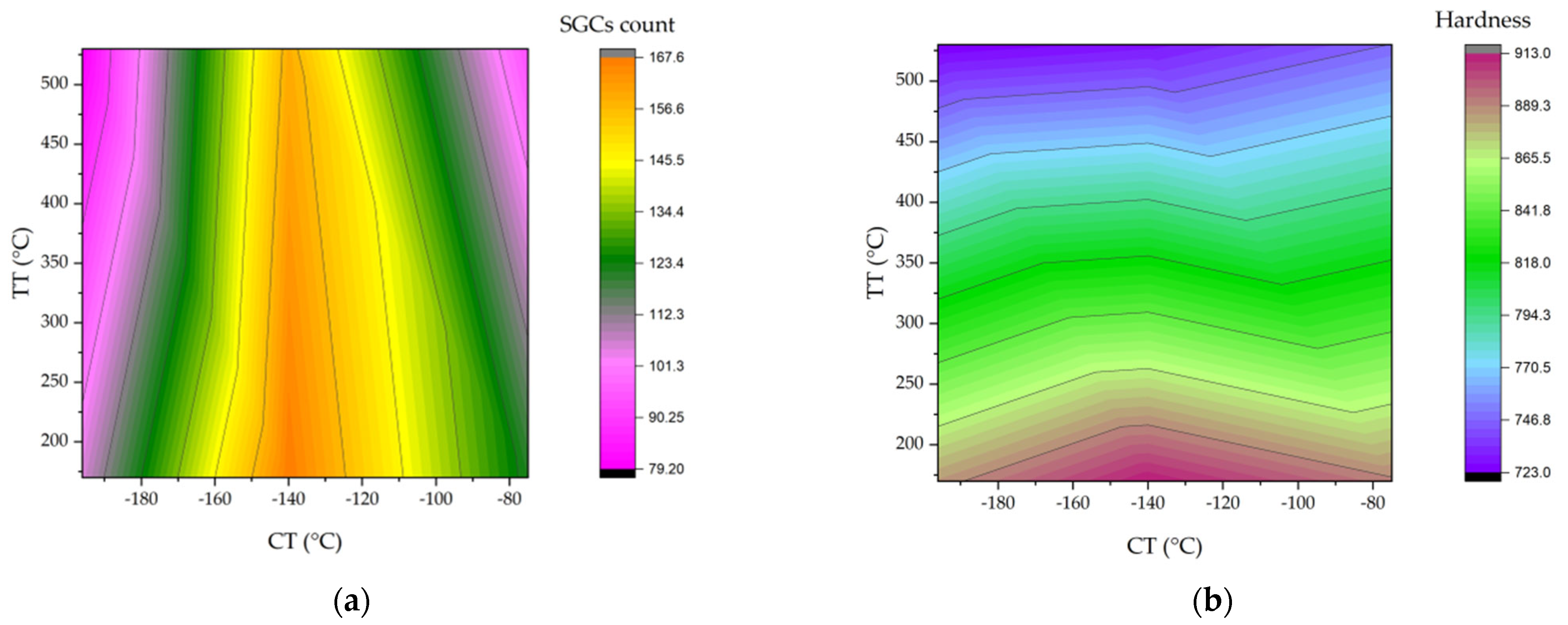
3.2. Hardness and Fracture Toughness (KIC)
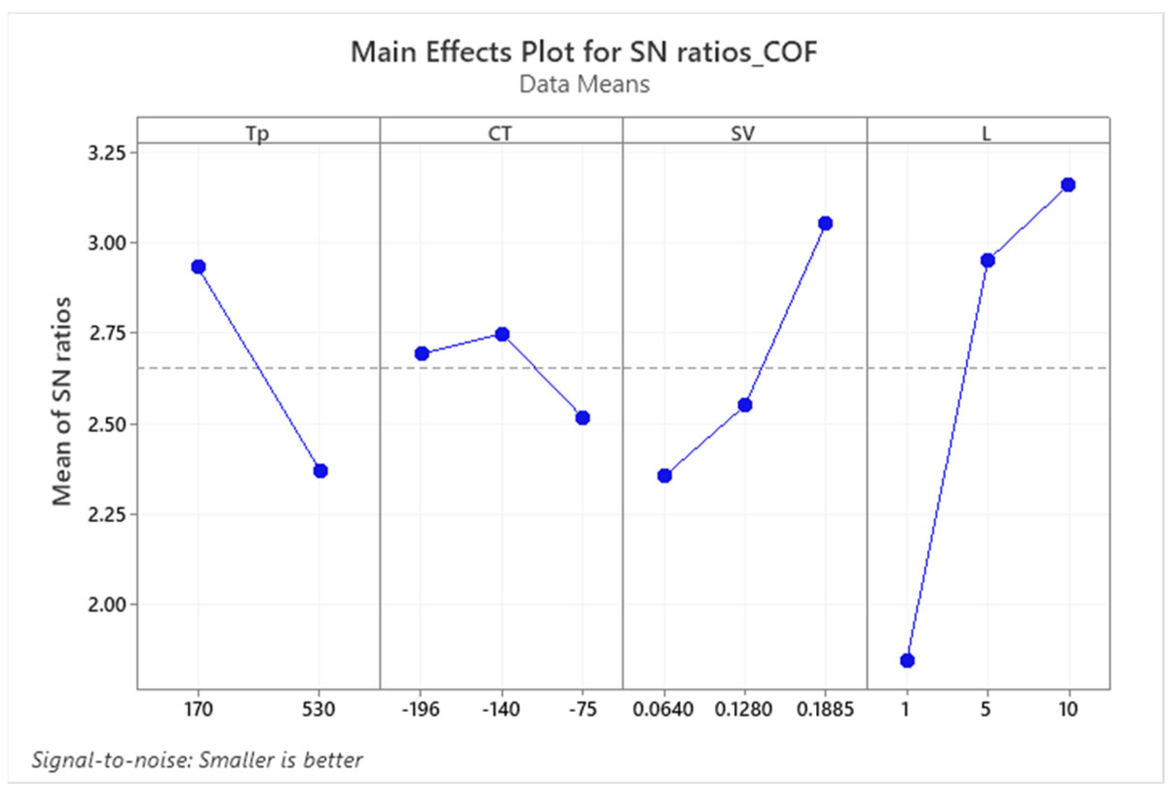
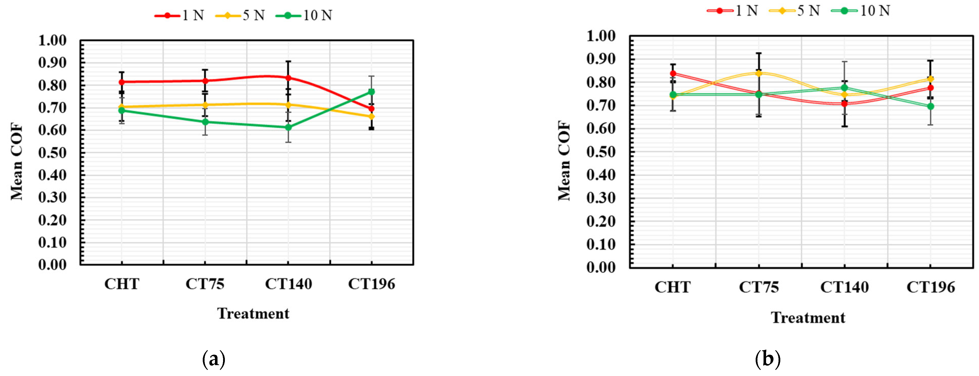
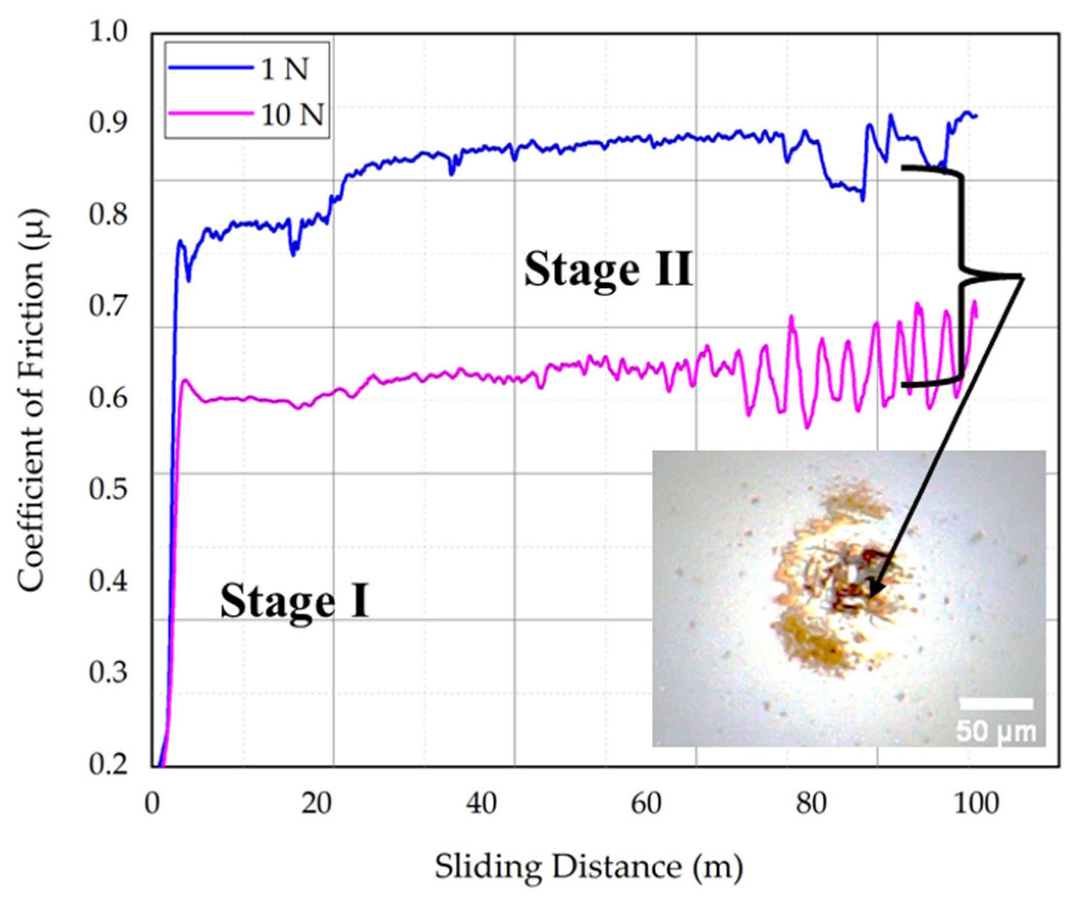
3.3. Coefficient of Friction (COF)
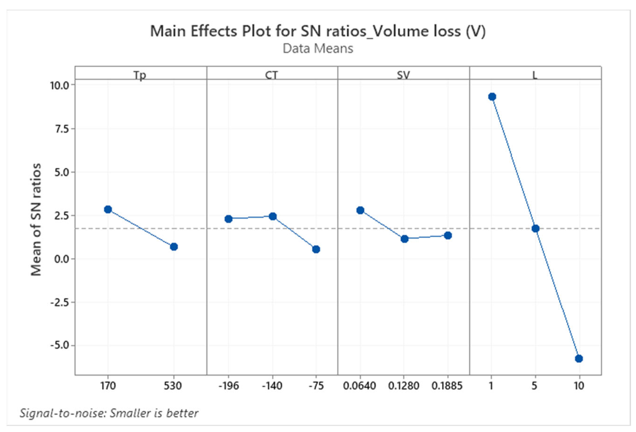
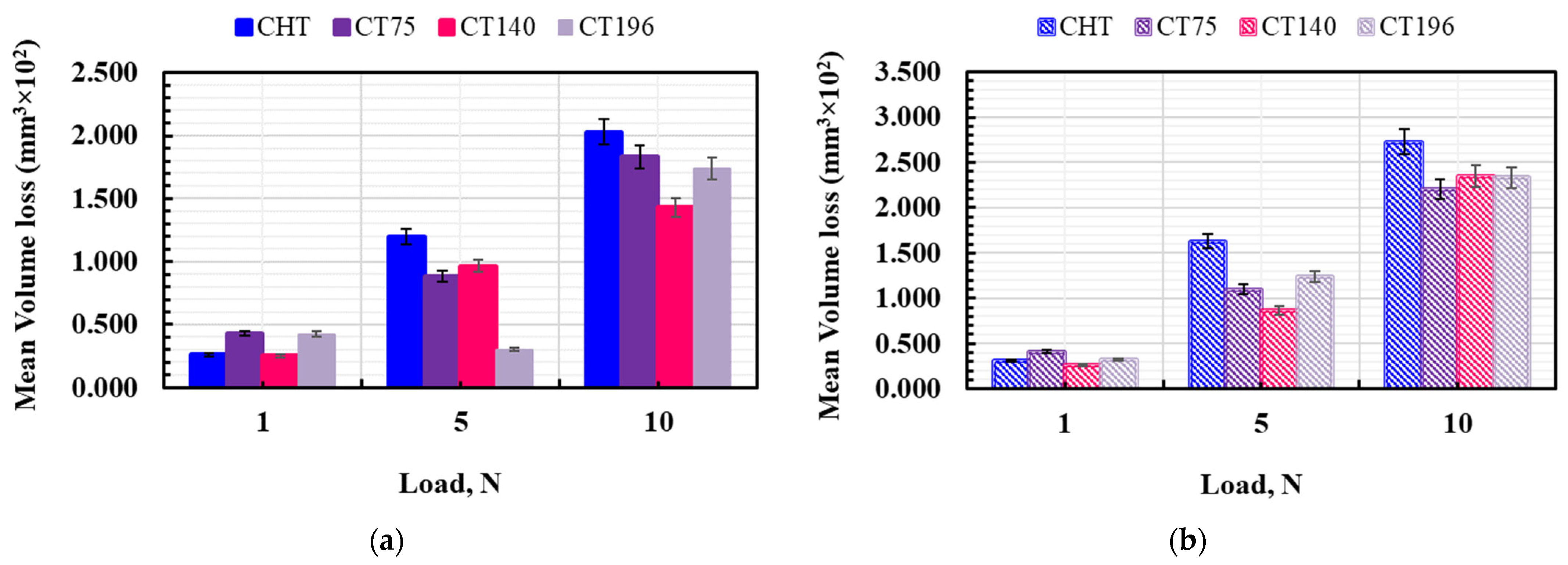
3.4. Volume Loss (V)
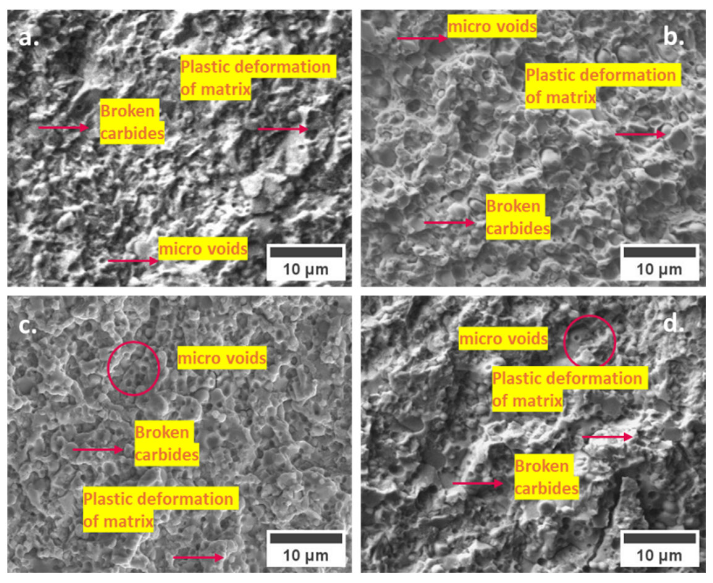
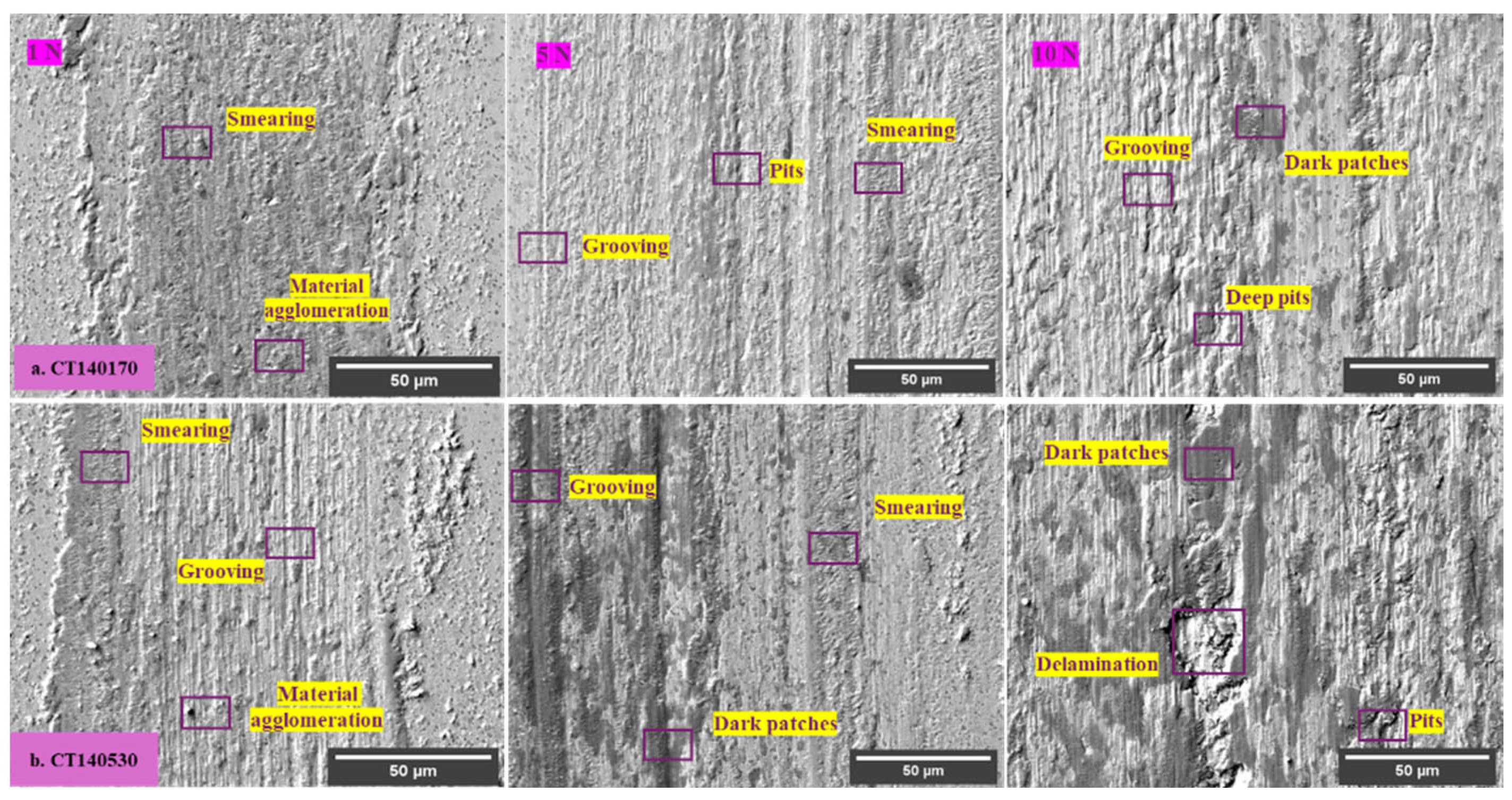
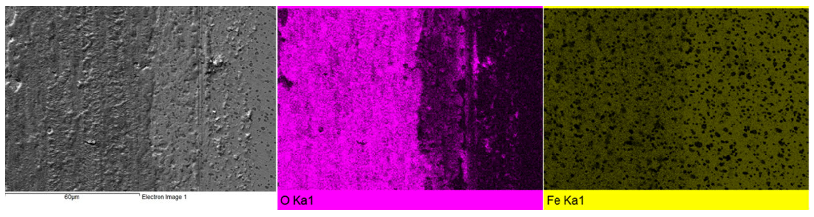
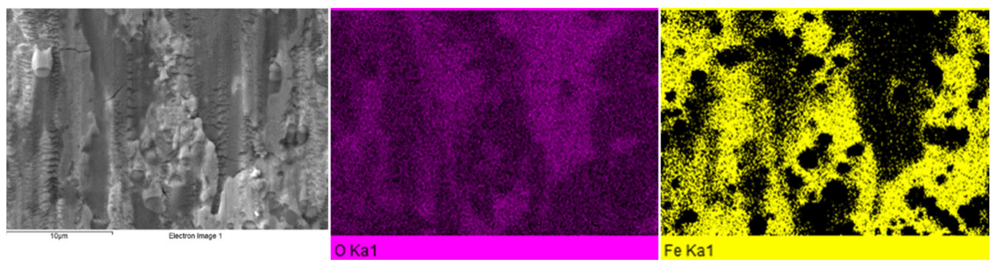
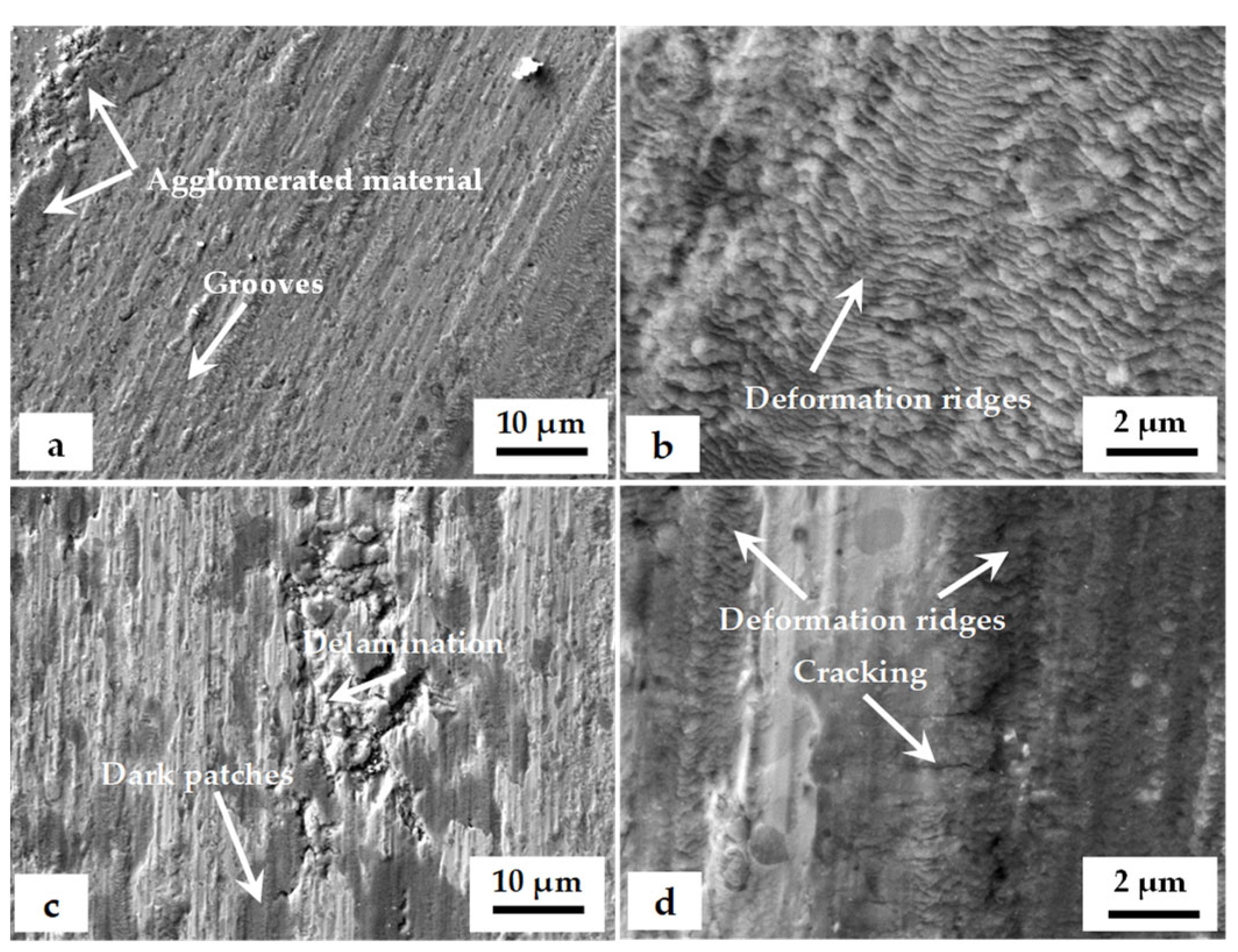
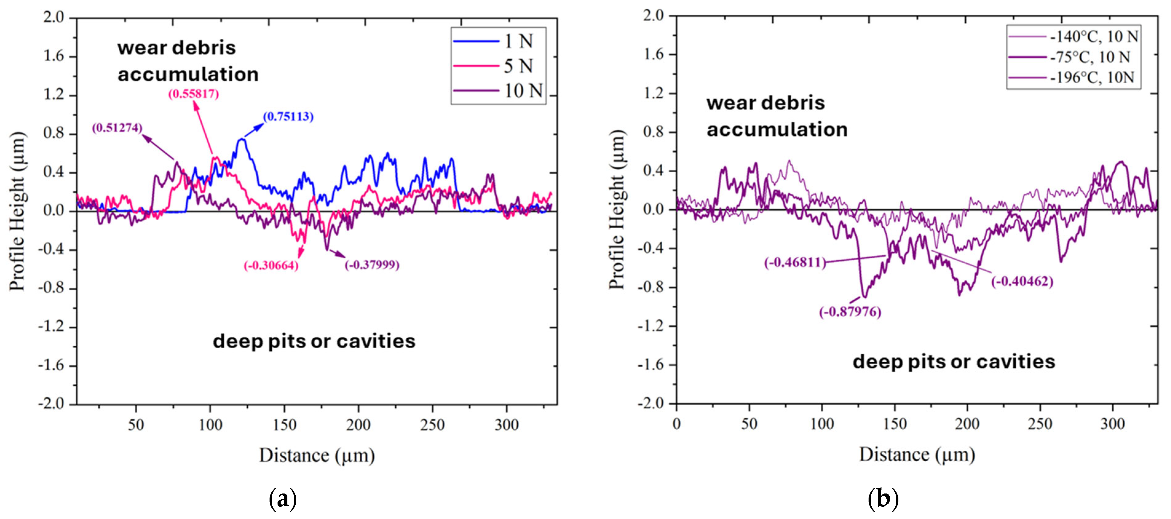
3.5. Worn Surface Characterization
4. Conclusions
Author Contributions
Funding
Institutional Review Board Statement
Informed Consent Statement
Data Availability Statement
Conflicts of Interest
References
- Moscoso, M.F.C.; Ramos, F.D.; De Lima Lessa, C.R.; Cunha, P.H.C.P.; Toniolo, J.C.; Lemos, G.V.B. Effects of Cooling Parameter and Cryogenic Treatment on Microstructure and Fracture Toughness of AISI D2 Tool Steel. J. Mater. Eng. Perform. 2020, 29, 7929–7939. [Google Scholar] [CrossRef]
- Gobbi, S.J.; Gobbi, V.J.; Reinke, G.; Muterlle, P.V.; Rosa, D.M. Ultra-Low-Temperature Process Effects on Microscale Abrasion of Tool Steel AISI D2. Mater. Sci. Technol. 2019, 35, 1355–1364. [Google Scholar] [CrossRef]
- Nanesa, H.G.; Touazine, H.; Jahazi, M. Influence of Cryogenic Process Parameters on Microstructure and Hardness Evolution of AISI D2 Tool Steel. Int. J. Adv. Manuf. Technol. 2016, 85, 881–890. [Google Scholar] [CrossRef]
- Li, J.; Zhang, X.; Bu, H.; Qi, H.; Zuo, P.; Li, S.; Li, M. Effects of Deep Cryogenic Treatment on the Microstructure Evolution, Mechanical and Thermal Fatigue Properties of H13 Hot Work Die Steel. J. Mater. Res. Technol. 2023, 27, 8100–8118. [Google Scholar] [CrossRef]
- Gecu, R. Combined Effects of Cryogenic Treatment and Tempering on Microstructural and Tribological Features of AISI H13 Steel. Mater. Chem. Phys. 2022, 292, 126802. [Google Scholar] [CrossRef]
- Xu, G.; Huang, P.; Feng, Z.; Wei, Z.; Zu, G. Effect of Deep Cryogenic Time on Martensite Multi-Level Microstructures and Mechanical Properties in AISI M35 High-Speed Steel. Materials 2022, 15, 6618. [Google Scholar] [CrossRef] [PubMed]
- Parcianello, C.T.; Fantineli, D.G.; Rosendo, T.S.; Reguly, A.; Tier, M.A.D. Influence of the Heat Treatment on the Mechanical and Tribological Properties of Cryogenically Treated AISI M2 Steel. J. Mater. Res. Technol. 2023, 26, 6462–6475. [Google Scholar] [CrossRef]
- Jovičević-Klug, P.; Jovičević-Klug, M.; Thormählen, L.; McCord, J.; Rohwerder, M.; Godec, M.; Podgornik, B. Austenite Reversion Suppression with Deep Cryogenic Treatment: A Novel Pathway towards 3rd Generation Advanced High-Strength Steels. Mater. Sci. Eng. A 2023, 873, 145033. [Google Scholar] [CrossRef]
- Yang, Z.; Liu, Z.; Liang, J.; Yang, Z.; Sheng, G. Elucidating the Role of Secondary Cryogenic Treatment on Mechanical Properties of a Martensitic Ultra-High Strength Stainless Steel. Mater. Charact. 2021, 178, 111277. [Google Scholar] [CrossRef]
- Dhokey, N.B.; Thakur, C.; Ghosh, P. Influence of Intermediate Cryogenic Treatment on the Microstructural Transformation and Shift in Wear Mechanism in AISI D2 Steel. Tribol. Trans. 2021, 64, 91–100. [Google Scholar] [CrossRef]
- Ďurica, J.; Ptačinová, J.; Dománková, M.; Čaplovič, L.; Čaplovičová, M.; Hrušovská, L.; Malovcová, V.; Jurči, P. Changes in Microstructure of Ledeburitic Tool Steel Due to Vacuum Austenitizing and Quenching, Sub-Zero Treatments at −140 °C and Tempering. Vacuum 2019, 170, 108977. [Google Scholar] [CrossRef]
- Nanesa, H.G.; Jahazi, M.; Naraghi, R. Martensitic Transformation in AISI D2 Tool Steel during Continuous Cooling to 173 K. J. Mater. Sci. 2015, 50, 5758–5768. [Google Scholar] [CrossRef]
- Das, D.; Dutta, A.K.; Ray, K.K. On the Enhancement of Wear Resistance of Tool Steels by Cryogenic Treatment. Philos. Mag. Lett. 2008, 88, 801–811. [Google Scholar] [CrossRef]
- Das, D.; Dutta, A.K.; Toppo, V.; Ray, K.K. Effect of Deep Cryogenic Treatment on the Carbide Precipitation and Tribological Behavior of D2 Steel. Mater. Manuf. Process. 2007, 22, 474–480. [Google Scholar] [CrossRef]
- Das, D.; Dutta, A.K.; Ray, K.K. Influence of Varied Cryotreatment on the Wear Behavior of AISI D2 Steel. Wear 2009, 266, 297–309. [Google Scholar] [CrossRef]
- Das, D.; Ray, K.K.; Dutta, A.K. Influence of temperature of sub-zero treatments on the wear behaviour of die steel. Wear 2009, 267, 1361–1370. [Google Scholar] [CrossRef]
- Amini, K.; Akhbarizadeh, A.; Javadpour, S. Effect of Deep Cryogenic Treatment on the Formation of Nano-Sized Carbides and the Wear Behavior of D2 Tool Steel. Int. J. Miner. Metall. Mater. 2012, 19, 795–799. [Google Scholar] [CrossRef]
- Korade, D.N.; Ramana, K.V.; Jagtap, K.R.; Dhokey, N.B. Effect of Deep Cryogenic Treatment on Tribological Behaviour of D2 Tool Steel-An Experimental Investigation. Mater. Today Proc. 2017, 4, 7665–7673. [Google Scholar] [CrossRef]
- Schulz, A.; Cui, C.; Steinbacher, M.; Ümit, T.; Wunde, M.; Jung, I.; Acar, S.; Nürnberger, F.; Gerstein, G.; Herbst, S.; et al. Effects of Cryogenic Treatment on the Microstructure and Mechanical Properties of High-Alloyed Tool Steels: Auswirkungen Der Kryobehandlung Auf Die Mikrostruktur Und Die Mechanischen Eigenschaften Hochlegierter Werkzeugstähle. HTM J. Heat Treat. Mater. 2020, 75, 73–93. [Google Scholar] [CrossRef]
- Jurči, P.; Dománková, M.; Hudáková, M.; Ptačinová, J.; Pašák, M.; Palček, P. Characterization of Microstructure and Tempering Response of Conventionally Quenched, Short- and Long-Time Sub-Zero Treated PM Vanadis 6 Ledeburitic Tool Steel. Mater. Charact. 2017, 134, 398–415. [Google Scholar] [CrossRef]
- Kusý, M.; Rízeková-Trnková, L.; Krajčovič, J.; Dlouhý, I.; Jurči, P. Can Sub-Zero Treatment at −75 °C Bring Any Benefits to Tools Manufacturing? Materials 2019, 12, 3827. [Google Scholar] [CrossRef] [PubMed]
- Jurči, P.; Ďurica, J.; Dlouhý, I.; Horník, J.; Planieta, R.; Kralovič, D. Application of −140 °C Sub-Zero Treatment for Cr-V Ledeburitic Steel Service Performance Improvement. Metall. Mater. Trans. A 2019, 50, 2413–2434. [Google Scholar] [CrossRef]
- ISO 12137: 2010; Metallic Materials–Determination of Plane Strain Fracture Toughness. International Organization for Standardization: Geneva, Switzerland, 2010.
- US-ASTM. ASTM G99; Test Method for Wear Testing with a Pin-on-Disk Apparatus. ASTM International: West Conshohocken, PA, USA, 2017. [Google Scholar]
- Achuthamenon Sylajakumari, P.; Ramakrishnasamy, R.; Palaniappan, G. Taguchi Grey Relational Analysis for Multi-Response Optimization of Wear in Co-Continuous Composite. Materials 2018, 11, 1743. [Google Scholar] [CrossRef] [PubMed]
- Das, D.; Ray, K.K. On the Mechanism of Wear Resistance of Tool Steels by Deep Cryogenic Treatment. Philos. Mag. Lett. 2012, 92, 295–303. [Google Scholar] [CrossRef]
- Das, D.; Ray, K.K. Structure–Property Correlation of Sub-Zero Treated AISI D2 Steel. Mater. Sci. Eng. A 2012, 541, 45–60. [Google Scholar] [CrossRef]
- Cardoso, P.H.S.; Israel, C.L.; da Silva, M.B.; Klein, G.A.; Soccol, L. Effects of Deep Cryogenic Treatment on Microstructure, Impact Toughness and Wear Resistance of an AISI D6 Tool Steel. Wear 2020, 456–457, 203382. [Google Scholar] [CrossRef]
- Podgornik, B.; Paulin, I.; Zajec, B.; Jacobson, S.; Leskovšek, V. Deep Cryogenic Treatment of Tool Steels. J. Mater. Process. Technol. 2016, 229, 398–406. [Google Scholar] [CrossRef]
- Jovičević-Klug, P.; Podgornik, B. Comparative Study of Conventional and Deep Cryogenic Treatment of AISI M3:2 (EN 1.3395) High-Speed Steel. J. Mater. Res. Technol. 2020, 9, 13118–13127. [Google Scholar] [CrossRef]
- Akhbarizadeh, A.; Amini, K.; Javadpour, S. Effects of Applying an External Magnetic Field during the Deep Cryogenic Heat Treatment on the Corrosion Resistance and Wear Behavior of 1.2080 Tool Steel. Mater. Des. 2012, 41, 114–123. [Google Scholar] [CrossRef]
- Akhbarizadeh, A.; Javadpour, S.; Amini, K. Investigating the Effect of Electric Current Flow on the Wear Behavior of 1.2080 Tool Steel during the Deep Cryogenic Heat Treatment. Mater. Des. 2013, 45, 103–109. [Google Scholar] [CrossRef]
- Akhbarizadeh, A.; Golozar, M.A.; Shafeie, A.; Kholghy, M. Effects of Austenizing Time on Wear Behavior of D6 Tool Steel after Deep Cryogenic Treatment. J. Iron Steel Res. Int. 2009, 16, 29–32. [Google Scholar] [CrossRef]
- Dhokey, N.B.; Nirbhavne, S. Dry Sliding Wear of Cryotreated Multiple Tempered D-3 Tool Steel. J. Mater. Process. Technol. 2009, 209, 1484–1490. [Google Scholar] [CrossRef]
- Arsič, D.; Lazič, V.; Mitrovič, S.; Džunič, D.; Aleksandrovič, S.; Djordjevič, M.; Nedeljkovič, B. Tribological behavior of four types of filler metals for hard facing under dry conditions. Ind. Lubr. Tribol. 2016, 68, 729–736. [Google Scholar] [CrossRef]
- Jurči, P.; Dlouhý, I. Cryogenic Treatment of Martensitic Steels: Microstructural Fundamentals and Implications for Mechanical Properties and Wear and Corrosion Performance. Materials 2024, 17, 548. [Google Scholar] [CrossRef]
- Meng, F.; Tagashira, K.; Azuma, R.; Sohma, H. Role of Eta-carbide Precipitation’s in the Wear Resistance Improvements of Fe-12Cr-Mo-V-1.4C Tool Steel by Cryogenic Treatment. ISIJ Int. 1994, 34, 205–210. [Google Scholar] [CrossRef]
- Yarasu, V.; Janka, L.; Jurči, P. Dry Sliding Wear Behaviour of Sub-Zero Processed Cr–V Ledeburitic Steel Vanadis 6 against Three Counterpart Types. Int. J. Mater. Res. 2020, 111, 894–907. [Google Scholar] [CrossRef]
- Leskovšek, V.; Kalin, M.; Vižintin, J. Influence of deep-cryogenic treatment on wear resistance of vacuum heat-treated HSS. Vacuum 2006, 80, 507–518. [Google Scholar] [CrossRef]
- García-León, R.A.; Martínez-Trinidad, J.; Zepeda-Bautista, R.; Campos-Silva, I.; Guevara-Morales, A.; Martínez-Londoño, J.; Barbosa-Saldaña, J. Dry Sliding Wear Test on Borided AISI 316L Stainless Steel under Ball-on-Flat Configuration: A Statistical Analysis. Tribol. Int. 2021, 157, 106885. [Google Scholar] [CrossRef]
- García-León, R.A.; Martínez-Trinidad, J.; Campos-Silva, I.; Figueroa-López, U.; Guevara-Morales, A. Wear Maps of Borided AISI 316L Steel under Ball-on-Flat Dry Sliding Conditions. Mater. Lett. 2021, 282, 128842. [Google Scholar] [CrossRef]
- Wang, S.Q.; Wei, M.X.; Zhao, Y.T. Effects of the Tribo-Oxide and Matrix on Dry Sliding Wear Characteristics and Mechanisms of a Cast Steel. Wear 2010, 269, 424–434. [Google Scholar] [CrossRef]
- Davis, J.R. Surface Hardening of Steels: Understanding the Basics; ASM International: West Conshohocken, PA, USA, 2002. [Google Scholar]
- Das, D.; Dutta, A.K.; Ray, K.K. Inconsistent wear behaviour of cryotreated tool steels: Role of mode and mechanism. Mater. Sci. Technol. 2009, 25, 1249–1257. [Google Scholar] [CrossRef]


| Chemical Composition (wt.%) | C | Si | Mn | Cr | Mo | V | Fe |
|---|---|---|---|---|---|---|---|
| Nominal | 2.1 | 1.0 | 0.4 | 6.8 | 1.5 | 5.4 | Bal. |
| Measured | 1.98 | 1.05 | 0.42 | 6.82 | 1.47 | 5.02 | Bal. |
| Source | DF | Seq SS | Adj SS | Adj MS | F | P | %C |
|---|---|---|---|---|---|---|---|
| Tp | 1 | 1.419 | 1.419 | 1.419 | 10.10 | 0.010 | 13.47 |
| CT | 2 | 0.177 | 0.177 | 0.088 | 0.63 | 0.552 | 1.68 |
| SV | 2 | 1.553 | 1.553 | 0.776 | 5.53 | 0.024 | 14.75 |
| L | 2 | 5.978 | 5.978 | 2.989 | 21.27 | 0.000 | 56.75 |
| Residual error | 10 | 1.405 | 1.405 | 0.140 | |||
| Total | 17 | 10.533 |
| Source | DF | Seq SS | Adj SS | Adj MS | F | P | %C |
|---|---|---|---|---|---|---|---|
| Tp | 1 | 20.963 | 20.963 | 20.963 | 2.33 | 0.158 | 3% |
| CT | 2 | 13.332 | 13.332 | 6.666 | 0.74 | 0.501 | 2% |
| SV | 2 | 9.843 | 9.843 | 4.922 | 0.55 | 0.595 | 1% |
| L | 2 | 686.335 | 686.335 | 343.167 | 38.1 | 0 | 84% |
| Residual error | 10 | 90.059 | 90.059 | 9.006 | |||
| Total | 17 | 820.531 |
| Cryogenic Treatment | Load, N | Wear Mechanism | Mode |
|---|---|---|---|
| CT75170 | 1 | Tribo-oxidative | Mild |
| CT75170 | 5 | Delaminative | Severe |
| CT75170 | 10 | Delaminative | Severe |
| CT140170 | 1 | Tribo-oxidative | Mild |
| CT140170 | 5 | Mixed | Moderate |
| CT140170 | 10 | Delaminative | Severe |
| CT1196170 | 1 | Tribo-oxidative | Mild |
| CT196170 | 5 | Mixed | Moderate |
| CT196170 | 10 | Delaminative | Severe |
| CT75530 | 1 | Tribo-oxidative | Mild |
| CT75530 | 5 | Delaminative | Severe |
| CT75530 | 10 | Delaminative | Severe |
| CT140530 | 1 | Tribo-oxidative | Mild |
| CT140530 | 5 | Delaminative | Severe |
| CT140530 | 10 | Delaminative | Severe |
| CT196530 | 1 | Tribo-oxidative | Mild |
| CT196530 | 5 | Delaminative | Severe |
| CT196530 | 10 | Delaminative | Severe |
Disclaimer/Publisher’s Note: The statements, opinions and data contained in all publications are solely those of the individual author(s) and contributor(s) and not of MDPI and/or the editor(s). MDPI and/or the editor(s) disclaim responsibility for any injury to people or property resulting from any ideas, methods, instructions or products referred to in the content. |
© 2024 by the authors. Licensee MDPI, Basel, Switzerland. This article is an open access article distributed under the terms and conditions of the Creative Commons Attribution (CC BY) license (https://creativecommons.org/licenses/by/4.0/).
Share and Cite
Yarasu, V.; Jurci, P.; Ptacinova, J.; Dlouhy, I.; Hornik, J. Effect of Cryogenic Treatments on Hardness, Fracture Toughness, and Wear Properties of Vanadis 6 Tool Steel. Materials 2024, 17, 1688. https://doi.org/10.3390/ma17071688
Yarasu V, Jurci P, Ptacinova J, Dlouhy I, Hornik J. Effect of Cryogenic Treatments on Hardness, Fracture Toughness, and Wear Properties of Vanadis 6 Tool Steel. Materials. 2024; 17(7):1688. https://doi.org/10.3390/ma17071688
Chicago/Turabian StyleYarasu, Venu, Peter Jurci, Jana Ptacinova, Ivo Dlouhy, and Jakub Hornik. 2024. "Effect of Cryogenic Treatments on Hardness, Fracture Toughness, and Wear Properties of Vanadis 6 Tool Steel" Materials 17, no. 7: 1688. https://doi.org/10.3390/ma17071688
APA StyleYarasu, V., Jurci, P., Ptacinova, J., Dlouhy, I., & Hornik, J. (2024). Effect of Cryogenic Treatments on Hardness, Fracture Toughness, and Wear Properties of Vanadis 6 Tool Steel. Materials, 17(7), 1688. https://doi.org/10.3390/ma17071688