
Climatically Accelerated Material Processes Determining the Long-Term Reliability of Light-Emitting Diodes

 ,
,
Abstract
1. Introduction
2. Samples and Methods
- Temperature: 85 °C, 85% RH, atmospheric pressure, under ½ max. power conditions according to datasheets (ca. 10 mA pro chips) (Weiss Chamber WB3 I 80/40, product of Weisstechnik, Balingen, Germany);
- Duration: 150, 250, 500, 800, 1000 h ageing;
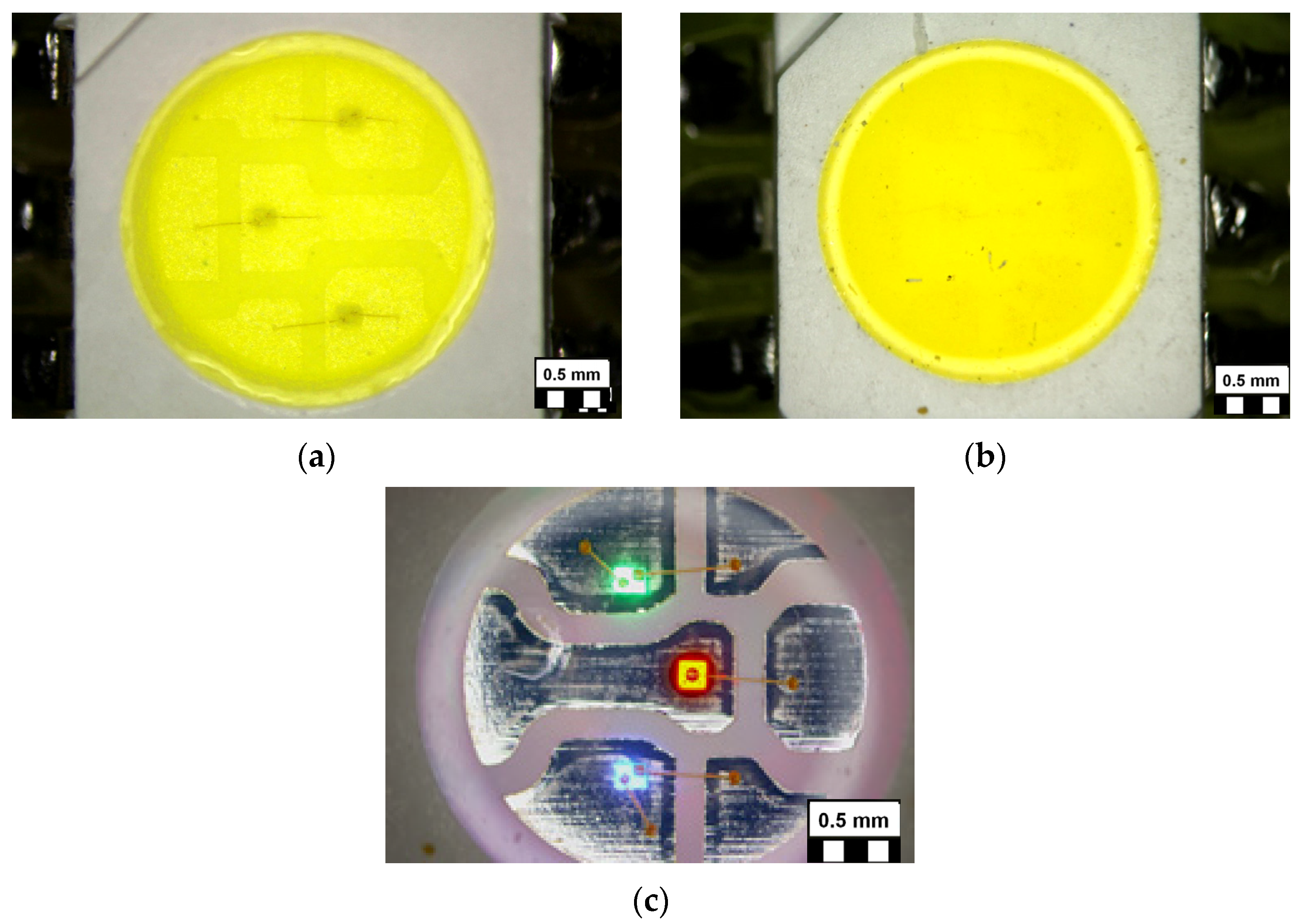
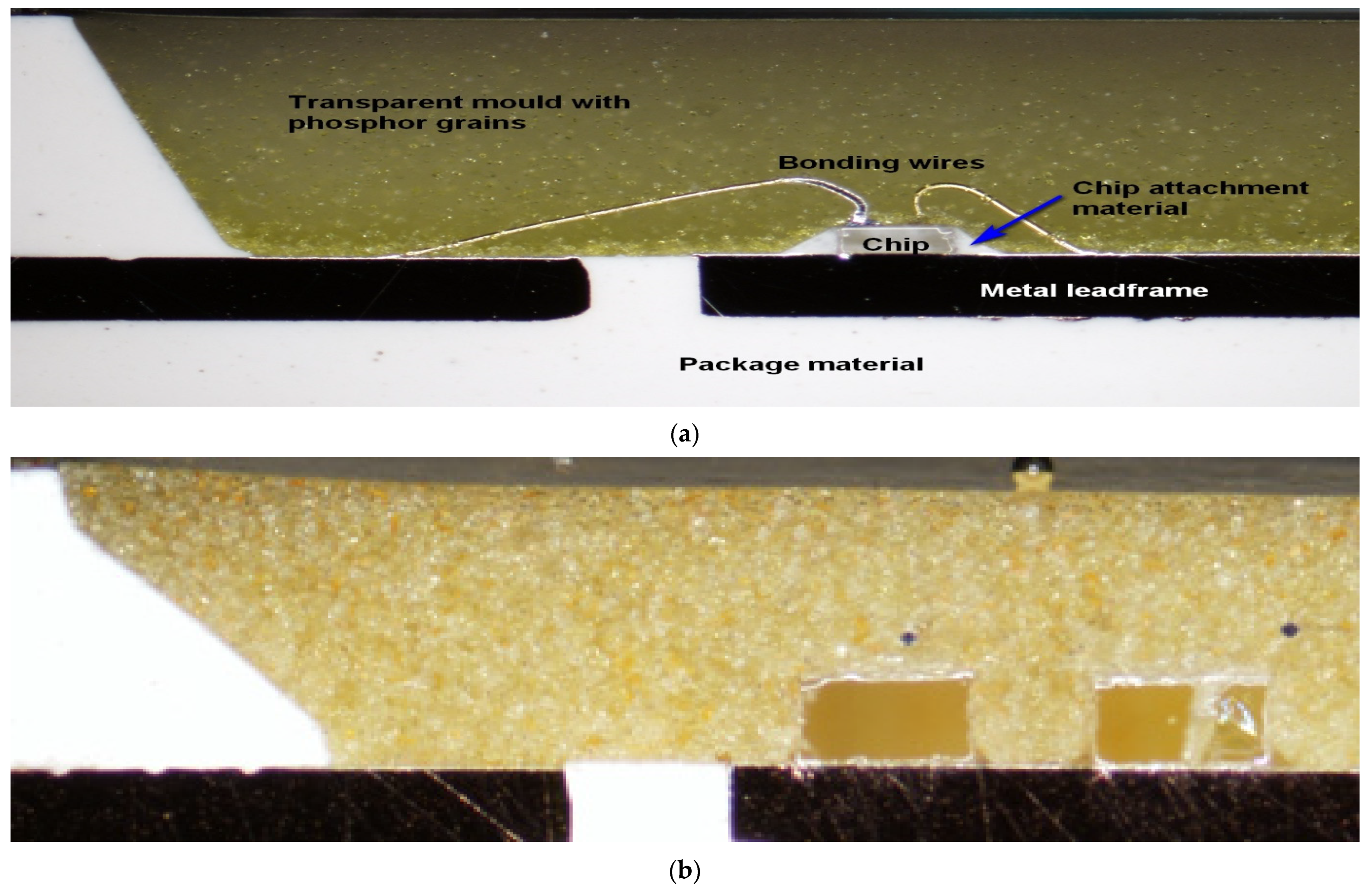
- Samples: pcCW, pcWW, and RGB 5050 SMD LEDs, 50 pieces of each type containing three chips/package, as shown in Figure 3. (All parts of the interconnection system on which the LEDs are mounted and soldered for the tests: printed circuit interconnection boards, soldered connections, and also those of the LED packages and connecting wires were covered by a silicone protective layer in order to avoid migrated shorts or other corrosion failures outside of the LED packages);
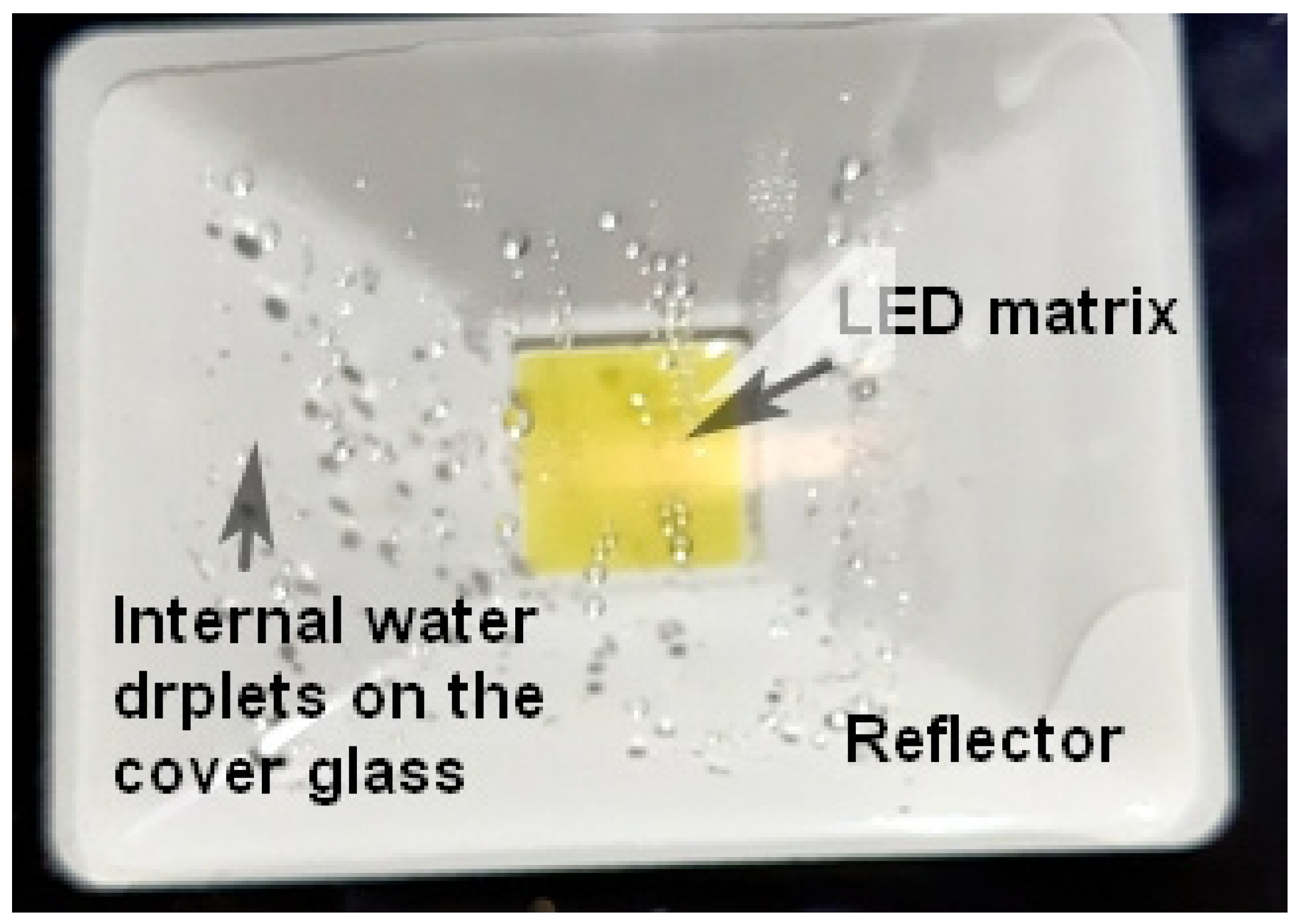
- Continuous visual inspection of all packages was performed during the ageing; samples were taken periodically for electrical/optical measurements;
- The overall measurement and test setup was (as described in previous studies [13]) a combined electrical, thermal, and radiometric/photometric measurement system complying with the recommendations of the electrical test method as per JEDEC JESD51-1 [32], JEDEC JESD51-51A and JESD51-52A standards [33,34], and the total flux measurement method for LEDs according to the CIE 225:20172007 document [35]. In such a setup the electrical powering of the LED under test is provided by the thermal test equipment. The light output of the LED is measured when it is driven by its prescribed operating current and is in thermal equilibrium (steady-state) as required by [35]. The reference temperature of the LED under test is the temperature of the cold plate which is attached to the integrating sphere of the photometric test system and the LEDs’ junction temperature is determined as recommended in [33]. For a schematic diagram and a detailed description of such a test setup, refer to [36];
- Optical microscopy (OM), scanning electron microscopy (SEM), and related electron dispersed X-ray (EDX) analysis and other microanalysis methods (see later) were used to reveal the background of the ageing processes resulting in the parameter changes of the LEDs and leading to possible failure.
3. Results
3.1. Physical Parameter Changes and Outlook
- The electrical “diode” behaviour of the parameters did not change significantly;
- The junction to ambient thermal resistance changed slightly in the range of accuracy in the case of warm white (WW) LEDs, but there was a significantly large increase in the case of cool white (CW) LEDs, which could be explained by the degradation (or delamination) of the chip attachment glue, as described elsewhere [17,37]. The reason could be that in the case of pcCW LED the moisture ingress reaches the chip and under-laying attachment glue level. The junction temperature also increased following similar large differences;
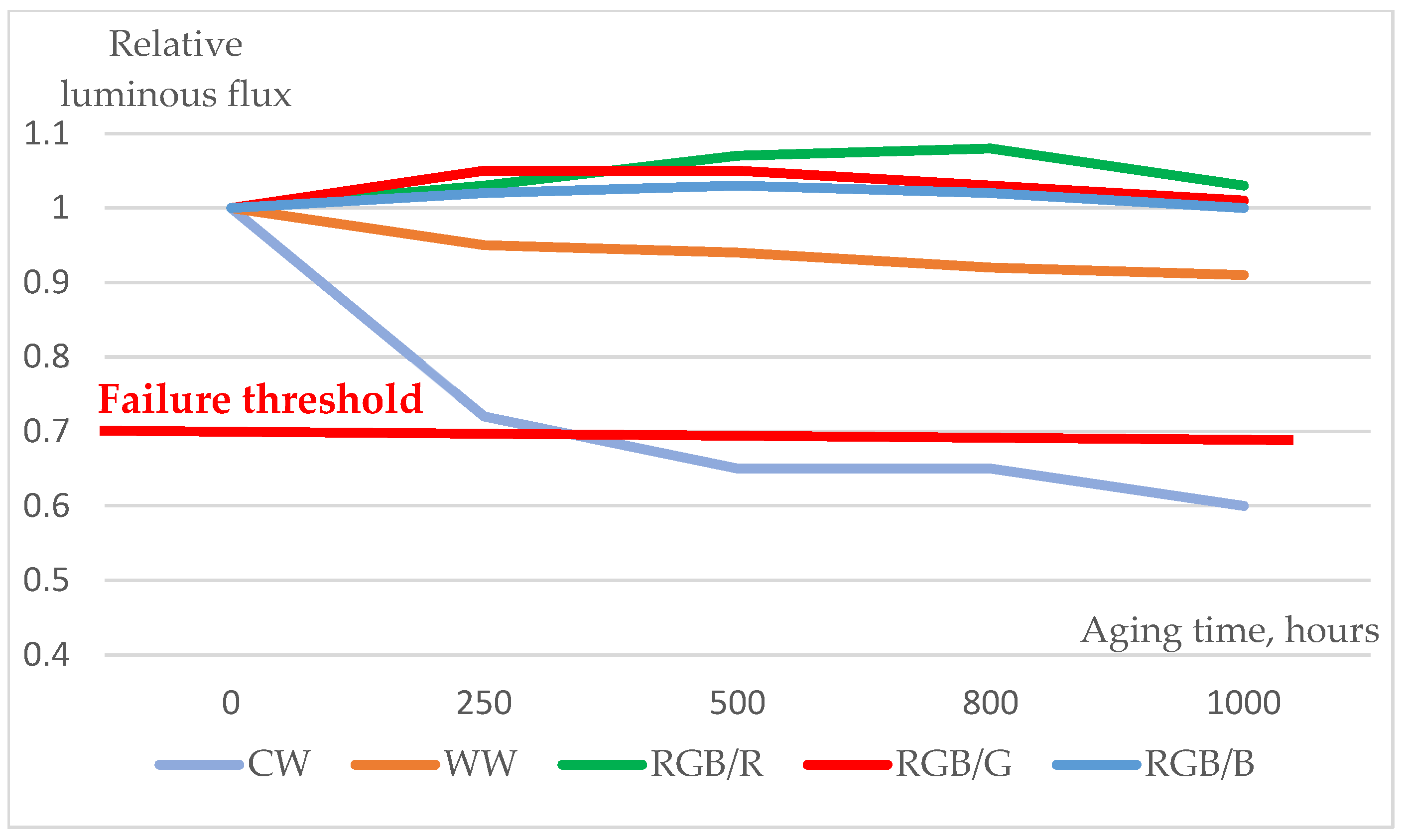
- Similar pronounced differences can be recognized in other parameters: in the case of CW LEDs, the dissipated (thermal) power increased significantly and a strong decrease in the radiant flux (emitted optical power) was detected at the same time. This may be the result of the degradation of the chip [3,5], that of the phosphor, or the darkening of the transparent and reflective layers [2,4,5,21]. The devices have to be regarded as “failed”, luminous flux maintenance shrunk to 62% as opposed to the commonly used 70% level as the failure threshold. These degradations are much smaller or negligible in the case of the WW LEDs, and the luminous flux maintenance remained higher than 90% even after 1000 h of 85/85 ageing.
- The electrical characteristics practically did not change;
- The thermal resistance from the chip to the environment (ambient temperature) of the red and green chips changed only slightly, while in the case of the blue chip, a significant (60%) increase was measured but the junction temperatures (at room temperature test conditions) increased only by a few centigrade only; the reason could be that in the case of pcCW LED, the moisture ingress reaches the chip and under-laying attachment glue level;
- Despite the thermal resistance changes, the emitted total luminous and radiant fluxes suffered very small changes of a few percent or even zero in the case of the blue chips. The reason is explained generally by the rearrangement of interstitial dopants and/or dislocation movement to the surfaces in the single crystal compound semiconductor materials of the LED chips. The degradation of the chips themselves cannot be observed during the investigated ageing period;
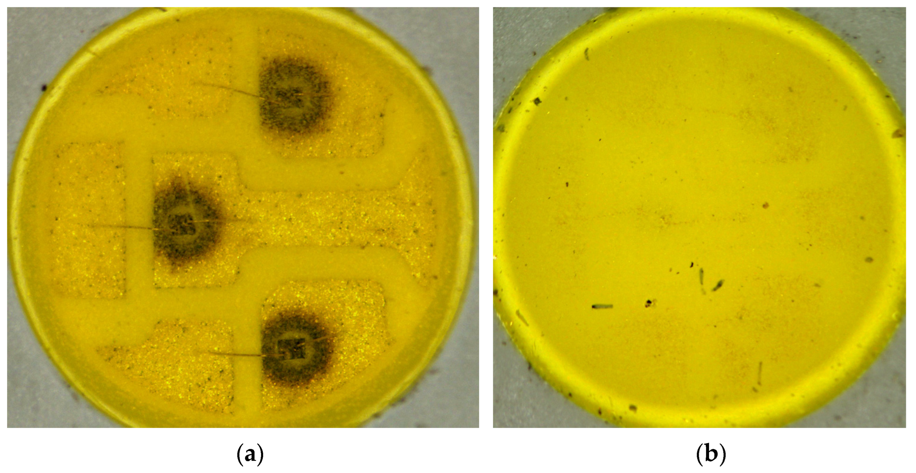
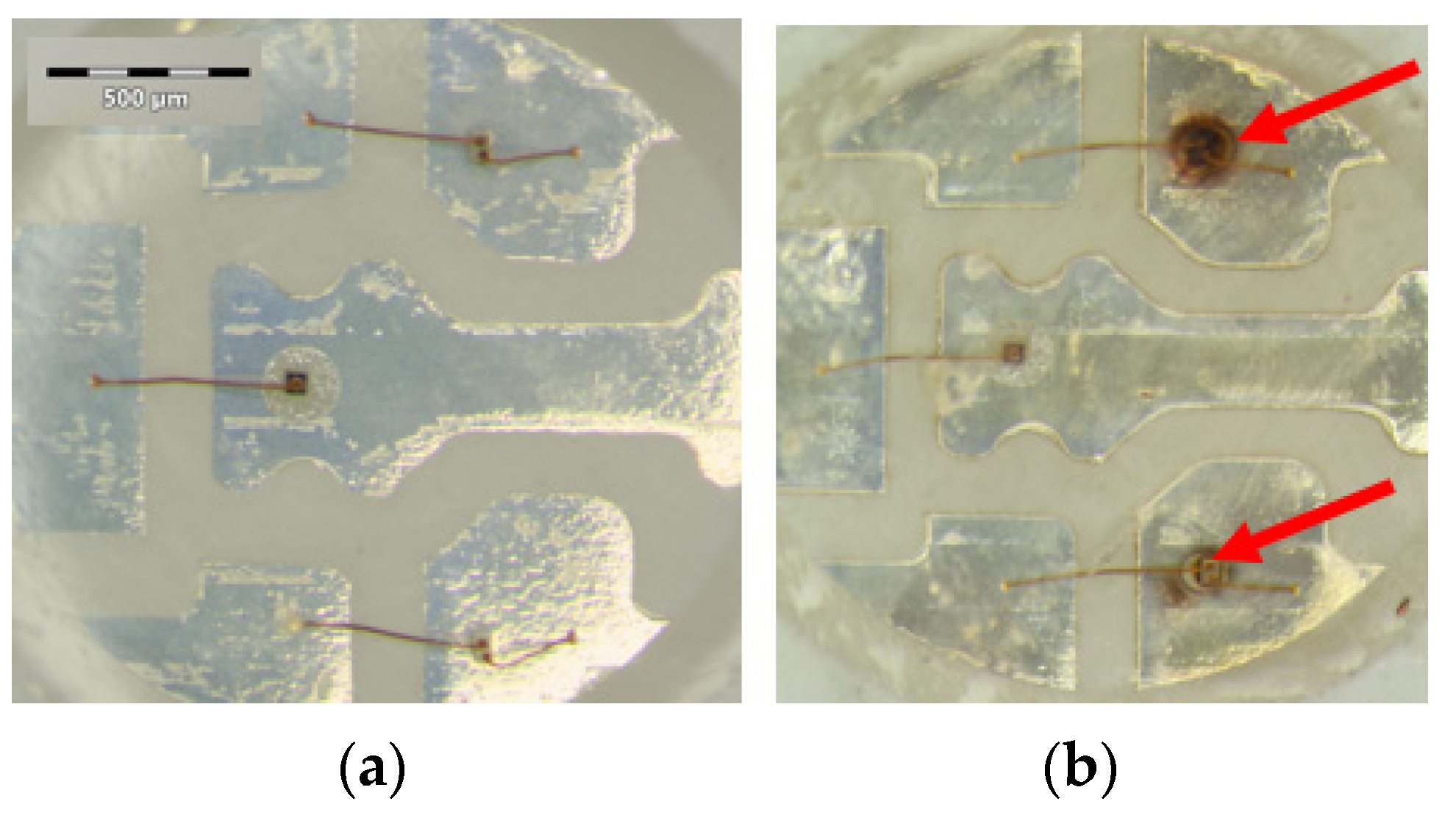
- No changes was recognized after 150 h of 85/85 ageing, while after 1000 h, strong brown rings were formed around the die attach glue of the green and blue LEDs, indicating some kind of degradation (may be carbonization of the epoxy component of the heat conducting insulating composite glue). The red LED’s conducting glue was not corroded even though it may have contained silver.
3.2. Changes in LEDs’ Spectra
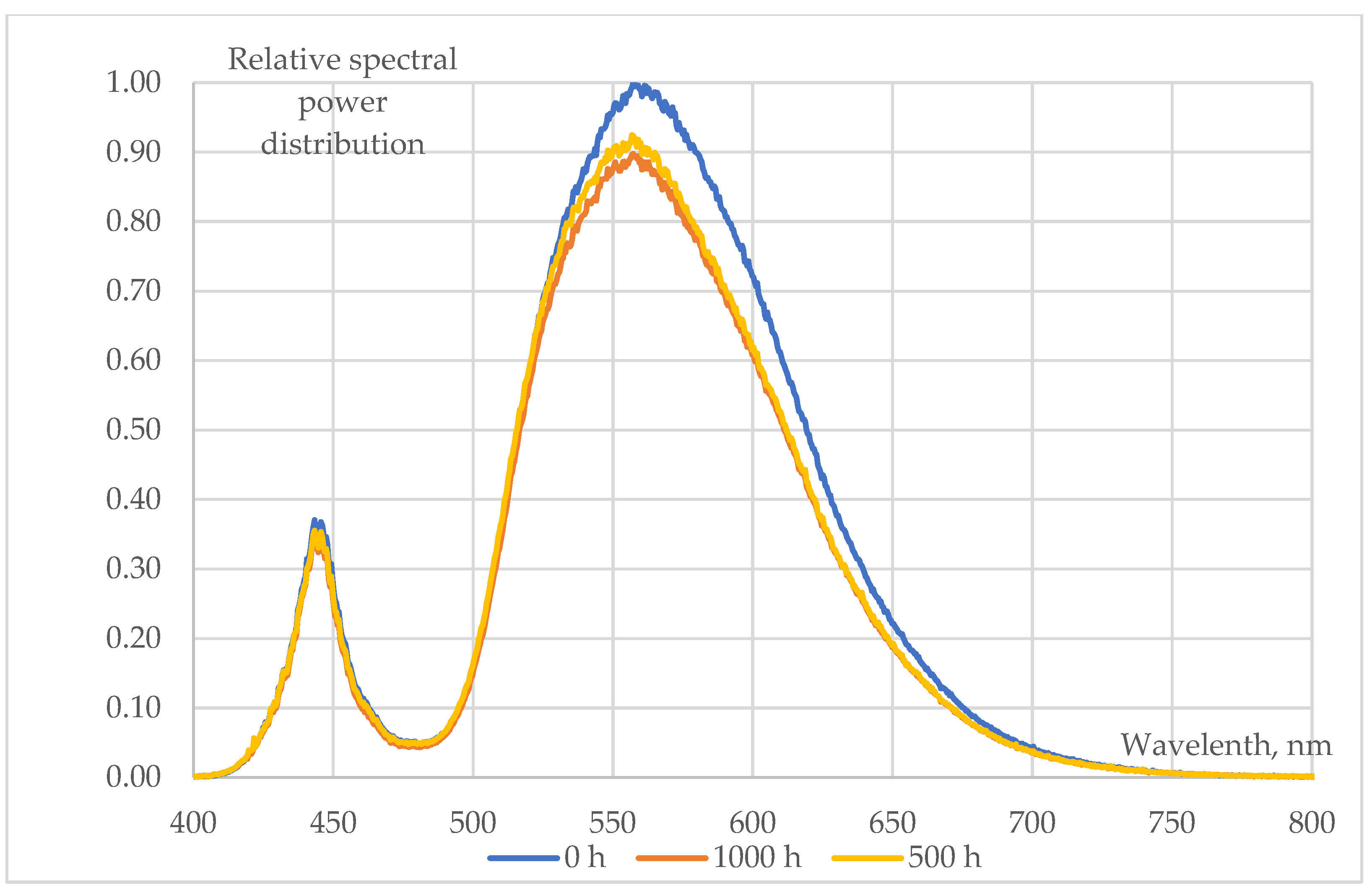
- The behaviour of phosphor-converted cool white (pcCW) LEDs is shown in Figure 6. The spectral intensities showed a significant decrease in both the blue (blue chips are used for excitation) and the yellow peak, indicating that the degradation may be present not only in the phosphor/polymer mould plastic (maybe mainly in the phosphor grains), but also at chip level at the blue die;
- A more moderate degradation was evidenced at the phosphor-converted warm white (pcCW) LED that is restricted mainly to the yellow phosphor. Since the ratio of the yellow/blue peak ratio is much larger, a larger phosphor grain concentration could be present within the mould material. No degradation of the blue pump chips was experienced in this case;
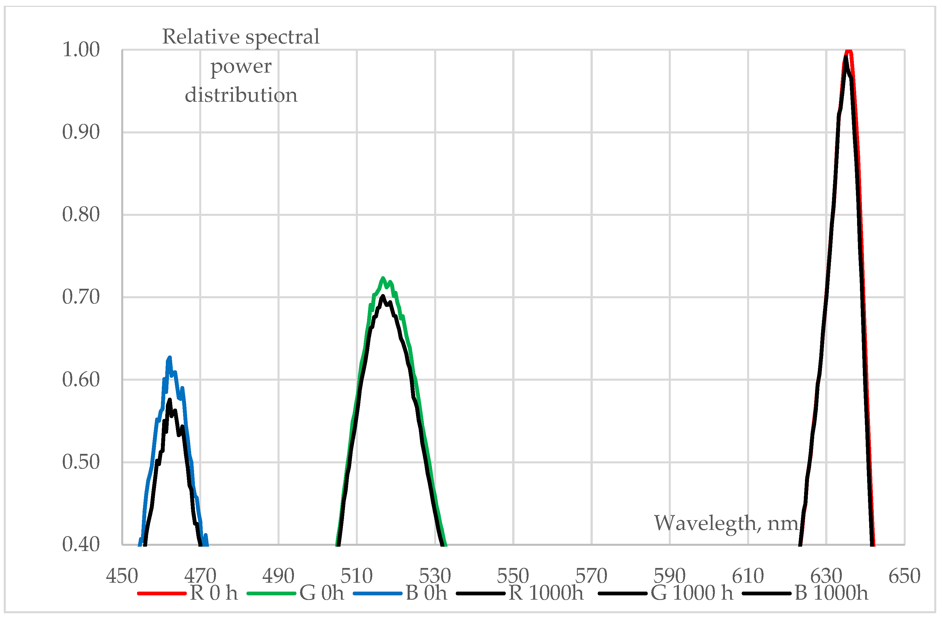
- Only very small changes in the blue, green and red LED spectra can be revealed, practically in the order of magnitude of the measurement uncertainty of the spectroradiometer that was used. This means that no degradation should be assumed either at the chip level or within the mould material, even though in Figure 5 some degradations can be seen at the insulating die attach glue material.
3.3. Luminous Loss
4. Discussion: Structural and Material Analysis
5. Conclusions
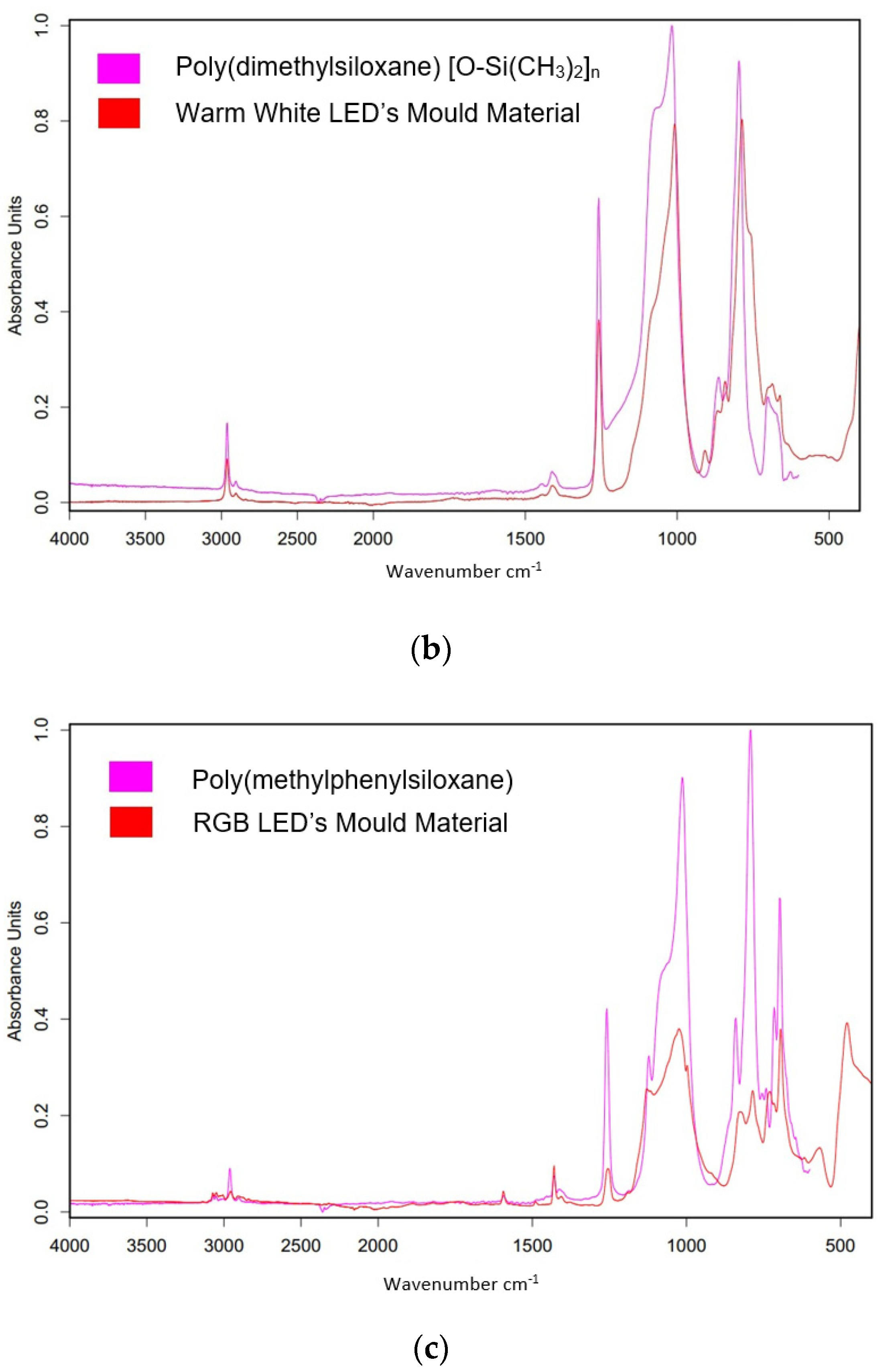
- RGB LEDs are much less sensitive to humidity ingress than the phosphor-converted white (pcW) LEDa. The reason is that the water molecule absorption and diffusion into the protective mould material are different; the PMPS protective material in RGB LEDs is much more withstanding against moisture absorption than the PDMS/phosphor composite in pcW types;
- The behaviour of phosphor-converted cool white (pcCW) and warm white (pcWW) was also different. The WW LED showed much less degradation during the ageing tests we performed, though the resulting luminous flux depreciation still might be acceptable subject to real-life mission profiles during their life span in LED-based illumination systems. CW LEDs have shown very fast and dramatic degradation leading to early parametric failure. The difference in their material structure is the concentration of the phosphor material within the plastic/phosphor composite layer. In WW LEDs, this layer has a large concentration and homogeneous distribution of the phosphor grains, while in CW LEDs only the bottom layer just above the chips contains phosphor;
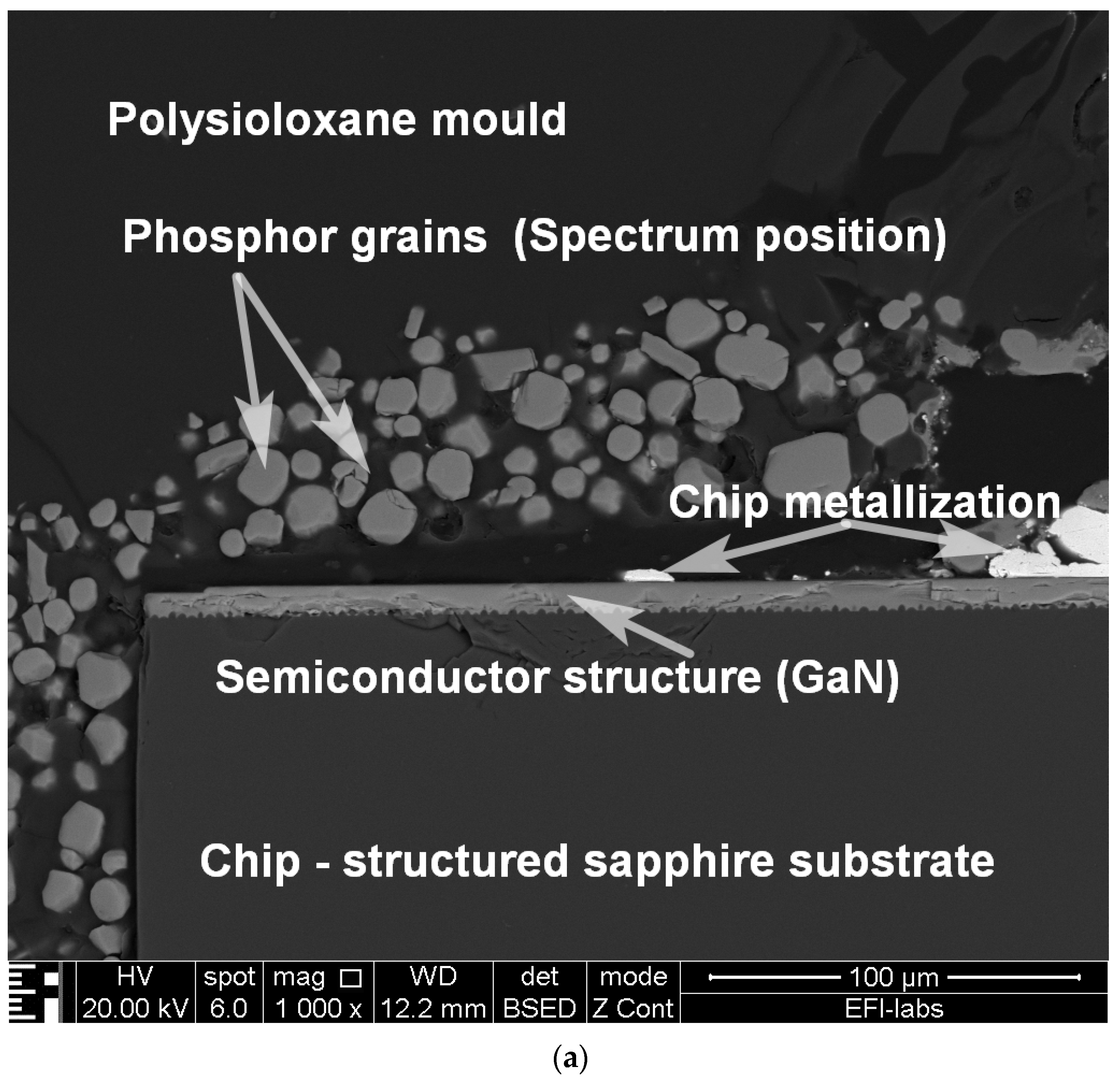
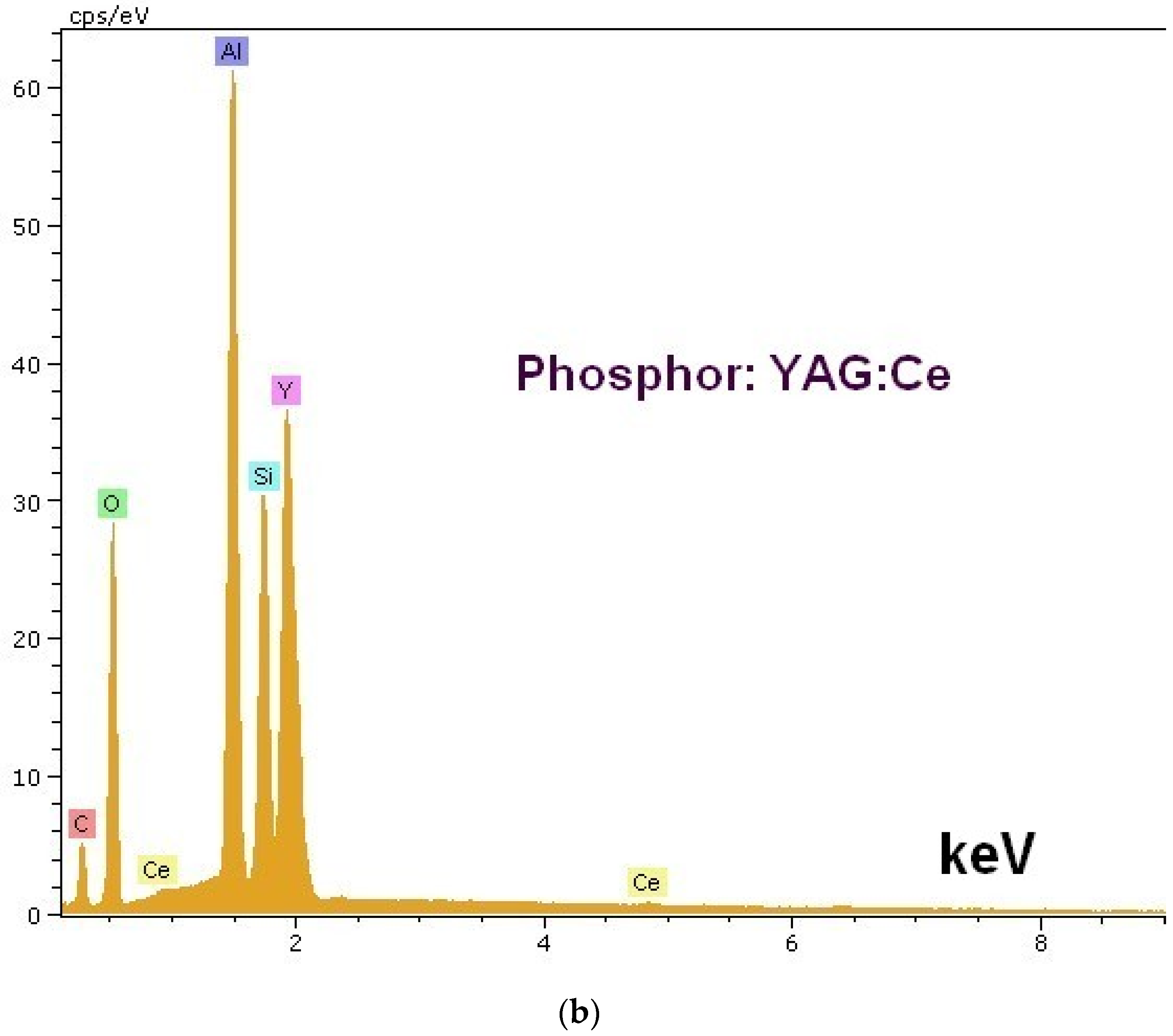
- The applied phosphor material in pcW LEDs (YAG:Ce) can react with water molecules and protect the bottom levels from moisture ingress in the WW LEDs. At the same time, the water molecules can reach the bottom level of the plastic/phosphor pool in the CW LEDs and thus result in chip-level degradation, lead frame metallization corrosion, and the degradation/delamination of the heat-conducting glue under the chips;
- As a final conclusion, it could be stated that in this experimental work, colour (RGB) LEDs were the most reliable and phosphor-converted cool white (pcCW) LEDs were found to be the most unstable in high-humidity environments.
Author Contributions
Funding
Institutional Review Board Statement
Informed Consent Statement
Data Availability Statement
Acknowledgments
Conflicts of Interest
References
- Van Driel, W.D.; Fan, X.J. (Eds.) Solid State Lighting Reliability (Components to Systems); Springer: New York, NY, USA, 2013. [Google Scholar] [CrossRef]
- van Driel, W.D.; Fan, X.J.; Zhang, G.Q. (Eds.) Solid State Lighting Reliability Part 2 (Components to Systems); Springer: Cham, Switzerland, 2018. [Google Scholar] [CrossRef]
- Chang, M.H.; Das, D.; Yarde, P.V.; Pecht, M. Light emitting diodes reliability review. Microelectron. Reliab. 2012, 52, 762–782. [Google Scholar] [CrossRef]
- van Driel, W.D.; Jacobs, B.; Watte, P.; Zhao, X. Reliability of LED-based Systems. Microelectron. Reliab. 2022, 129, 114477. [Google Scholar] [CrossRef]
- Kim, H.; Yang, H.; Huh, C.; Kim, S.-W.; Park, S.J.; Hwang, H. Electromigration induced Failure of GaN Multiquantum Well Light Emitting Diode. Electron. Lett. 2000, 36, 908–910. [Google Scholar] [CrossRef]
- Meneghini, M.; Trevisanello, L.; Sanna, C.; Mura, G.; Vanzi, M.; Meneghesso, G.; Zanoni, E. High temperature electro-optical degradation of InGaN/GaN HBLEDs. Microelectron. Reliab. 2007, 47, 1625–1629. [Google Scholar] [CrossRef]
- Meneghini, M.; Tazzoli, A.; Mura, G.; Meneghesso, G.; Zanoni, E. A Review on the Physical Mechanisms That Limit the Reliability of GaN-Based LEDs. IEEE Trans. Electron. Dev. 2010, 57, 108–118. [Google Scholar] [CrossRef]
- Trevisanello, L.; Zuani, F.D.; Meneghini, M.; Trivellin, N.; Zanoni, E.; Meneghesso, G. Thermally Activated Degradation and Package Instabilities of Low Flux LEDs. In Proceedings of the 47th Annual International Reliability Physics Symposium, Montreal, QC, Canada, 26–30 April 2009; pp. 98–103. [Google Scholar] [CrossRef]
- Buso, S.; Spiazzi, G.; Meneghini, M.; Meneghesso, G. Performance Degradation of High-Brightness Light Emitting Diodes Under DC and Pulsed Bias. IEEE Trans. Device Mater. Reliab. 2008, 8, 312–322. [Google Scholar] [CrossRef]
- Letha, S.S.; Bollen, M.H.J.; Rönnberg, S.K. Analysis and Recommendations for LED Catastrophic Failure Due to Voltage Stress. Energies 2022, 15, 540. [Google Scholar] [CrossRef]
- Yang, Y.-H.; Yen-Fu Su, Y.-F.; Chiang, K.-N. Acceleration Factor Analysis of Ageing Test on Gallium Nitride (GaN)-based High Power Lightemitting Diode (LED). In Proceedings of the 14th IEEE Intersociety Conference on Thermal and Thermomechanical Phenomena in Electronic Systems (ITHERM), Orlando, FL, USA, 27–30 May 2014; pp. 178–181. [Google Scholar] [CrossRef]
- Wu, H.; Zhou, L.; Luo, H.; Xiao, W.; Cao, M.; Hu, Y.; Jing, G.; Li, V. Research on Failure Mechanism of the Phosphors and Sealants for White Light Emitting Diode Package. In Proceedings of the 17th International Conference on Electronic Packaging Technology, Wuhan, China, 16–19 August 2016; pp. 1297–1300. [Google Scholar] [CrossRef]
- Poppe, A.; Molnár, G.; Temesvölgyi, T. Temperature dependent thermal resistance in power LED assemblies and a way to cope with it. In Proceedings of the 26th Annual IEEE Semiconductor Thermal Measurement and Management Symposium (SEMI-THERM), Santa Clara, CA, USA, 21–25 February 2010. [Google Scholar] [CrossRef]
- Hegedüs, J.; Hantos, G.; Poppe, A. Lifetime Modelling Issues of Power Light Emitting Diodes. Energies 2020, 13, 3370. [Google Scholar] [CrossRef]
- Hantos, G.; Hegedüs, J.; Rencz, M.; Poppe, A. Ageing Tendencies of Power LEDs Under Different Humidity Conditions During Thermal Reliability Testing. In Proceedings of the 21st Therminic Workshop, Paris, France, 30 September–2 October 2015; pp. 52–155. [Google Scholar] [CrossRef]
- Lall, P.; Zhang, H.; Davis, L. A Comparison of Temperature and Humidity Effects on Phosphor Converted LED Package and the Prediction of Remaining Useful Life with State Estimation. In Proceedings of the 15th IEEE Intersociety Conference on Thermal and Thermomechanical Phenomena in Electronic Systems (ITHERM), Las Vegas, NV, USA, 31 May–3 June 2016; pp. 207–216. [Google Scholar] [CrossRef]
- Hu, J.; Yang, L.; Shin, M.W. Mechanism and thermal effect of delamination in light-emitting diode packages. Microelectr. J. 2013, 38, 157–163. [Google Scholar] [CrossRef]
- Luo, X.; Fan, J.; Zhang, M.; Qian, C.; Fan, X.; Zhang, G. Degradation Mechanism Analysis for Phosphor/Silicone Composites Aged Under High Temperature and High Humidity Condition. In Proceedings of the 18th International Conference on Electronic Packaging Technology (ICEPT), Harbin, China, 16–19 August 2017; pp. 1330–1336. [Google Scholar] [CrossRef]
- Qin, Z.; Feng, J.; Zhaohui, C.; Ling, X.; Simin, W.; Sheng, L. Effect of temperature and moisture on the luminescence properties of silicone filled with YAG phosphor. J. Semicond. 2011, 32, 012002. [Google Scholar] [CrossRef]
- Huang, J.; Golubović, D.S.; Koh, S.; Yang, D.; Li, X.; Fan, X.; Zhang, G.Q. Degradation Modeling of Mid-Power White-light LEDs by Using Wiener Process. Opt. Express 2015, 23, A966–A978. [Google Scholar] [CrossRef] [PubMed]
- Singh, P.; Tan, C.M. Degradation Physics of High Power LEDs in Outdoor Environment and the Role of Phosphor in the Degradation Process. Sci. Rep. 2016, 6, 24052. [Google Scholar] [CrossRef] [PubMed]
- IESNA LM-80-08; “Measuring Lumen Maintenance of LED LightSources”. Subcommittee on Solid State Lighting of the IES Testing Procedures Committee: New York, NY, USA, 2008.
- The Solid–State Lighting Subcommittee of the IES Testing Procedures Committee. IESNA LM-80-20 Approved Method: Measuring Luminous Flux and Color Maintenance of LED Packages, Arrays and Modules. 2020. Available online: https://webstore.ansi.org/standards/iesna/ansiieslm8020 (accessed on 8 March 2024).
- Lutz, T.; Ritzer, M. Reliablily and Lifetime of LEDs. OSRAM Opto Semiconductors Application Note No. AN006. 2020. Available online: https://media.osram.info/media/img/osram-dam-2496614/AN006_Reliability_and_lifetime_of_LEDs.pdf (accessed on 8 March 2024).
- JEDEC JESD91A; “Method for Developing Acceleration Models for Electronic Component Failure Mechanisms”. JEDEC Solid State Technology Association: Arlingtomn, VA, USA, 2016.
- JEDEC JESD22-A101D.01 Steady-State Temperature-Humidity Bias Life Test. 2021. Available online: https://www.jedec.org/standards-documents/docs/jesd-22-a101c (accessed on 8 March 2024).
- Peck, D.S. Comprehensive Model for Humidity Testing Correlation. In Proceedings of the 24th IEEE Annual International Reliability Physics Symposium, Anaheim, CA, USA, 1–3 April 1986; pp. 44–50. [Google Scholar] [CrossRef]
- Carlson, C.; Schenkelberg, F. The Process of Reliability Engineering: Creating Reliability Plans that Add Value; FMS Reliability Publishing: Los Gatos, CA, USA, 2023; ISBN 978-1-938122-12-5. [Google Scholar]
- IEC 60529; Degrees of Protection Provided by Enclosures. 2001. Available online: https://webstore.iec.ch/preview/info_iec60529%7Bed2.1%7Db.pdf (accessed on 8 March 2024).
- JEDEC JESD22A110E-01 Highly Accelerated Temperature and Humidity Stress Test. 2021. Available online: https://www.jedec.org/standards-documents/docs/jesd-22-a110c (accessed on 8 March 2024).
- Hegedüs, J.; Hantos, G.; Poppe, A.; Kovács, R.; Bojta, P.; Harsányi, G. LED Lifetime Tests for Circuit Simulation Modelling. In Proceedings of the 30th Session of the CIE, Ljubljana, Slovenia, 15–23 September 2023; Volume 1, pp. 803–812. [Google Scholar] [CrossRef]
- JEDEC JESD51-1 Integrated Circuit Thermal Measurement Mehtod—Electrical Test Mehtod (Single Semiconductor Device. 1995. Available online: https://www.jedec.org/standards-documents/docs/jesd-51-1 (accessed on 8 March 2024).
- JEDEC JESD51-51A Standard Implementation of the Electrical Test Method for the Measurement of Real Thermal Resistance and Impedance of Light-Emitting Diodes with Exposed Cooling. 2022. Available online: https://www.jedec.org/standards-documents/docs/jesd51-51 (accessed on 8 March 2024).
- JEDEC JESD51-52A Guidelines for Combining CIE 127-2007/225:2017 Total Flux Measurements with Thermal Measurements of LEDs with Exposed Cooling Surface. 2022. Available online: https://www.jedec.org/standards-documents/docs/jesd51-52 (accessed on 8 March 2024).
- CIE. Optical Measurement of High-Power LEDs; Technical Report 225:2017; International Commission on Illumination, CIE: Vienna, Austria, 2017; ISBN 978-3-902842-12-1. [Google Scholar] [CrossRef]
- Farkas, G.; Poppe, A.; Sárkány, Z.; Vass-Várnai, A. Thermal Transient Measurements on Various Electronic Components. In Theory and Practice of Thermal Transient Testing of Electronic Components; Rencz, M., Farkas, G., Poppe, A., Eds.; Springer: Cham, Switzerland, 2022. [Google Scholar] [CrossRef]
- Koh, S.; Driel, W.V.D.; Zhang, G.Q. Thermal and moisture degradation in SSL system. In Proceedings of the 2012 13th International Thermal, Mechanical and Multi-Physics Simulation and Experiments in Microelectronics and Microsystems, Cascais, Portugal, 16–18 April 2012. [Google Scholar] [CrossRef]
- Cerium—Wikipedia. Available online: https://en.wikipedia.org/wiki/Cerium (accessed on 8 March 2024).


| Cool White | Warm White | |||
|---|---|---|---|---|
| Parameter | Original Value | After 1000 h of 85/85 Ageing | Original Value | After 1000 h of 85/85 Ageing |
| Forward voltage [V] | 3.1 | 3.1 | 2.9 | 2.9 |
| Electrical power [mW] | 92 | 92 | 87 | 87 |
| Heat dissipation [mW] | 77 | 82 | 62 | 64 |
| Emitted optical power [mW] | 15 | 10 | 25 | 23 |
| Energy conversion efficiency [%] | 16 | 11 | 29 | 26 |
| Thermal resistance [K/W] | 211 | 455 (∆ = −115%) | 115 | 117 (∆ = −1.7%) |
| Junction temperature [°C] | 42 | 62 | 32 | 32 |
| Total luminous flux [lm] | 4 | 2.5 (∆ = −38%) | 9.1 | 8.3 (∆ = −9%) |
| Efficacy lm/W | 43 | 27 | 105 | 95.4 |
| Correlated Color Temperature [K] | 11,900 | 4340 | 5315 | 5676 |
| Red | Green | Blue | ||||
|---|---|---|---|---|---|---|
| Parameter | Original Value | After 1000 h of 85/85 Ageing | Original Value | After 1000 h of 85/85 Ageing | Original Value | After 1000 h of 85/85 Ageing |
| Forward voltage [V] | 2.1 | 2.1 | 3.3 | 3.3 | 3.2 | 3.2 |
| Electrical power [mW] | 42 | 42 | 66 | 66 | 64 | 64 |
| Heat dissipation [mW] | 36 | 36 | 59 | 59 | 54 | 54 |
| Emitted optical power [mW] | 6 | 6 | 7 | 7 | 10 | 10 |
| Energy conversion efficiency [%] | 14 | 14 | 11 | 11 | 18 | 18 |
| Thermal resistance [K/W] | 254 | 280 (∆ = −10%) | 277 | 307 (∆ = −11%) | 235 | 375 (∆ = 60%) |
| Junction temperature [°C] | 34 | 35 | 41 | 43 | 37 | 41 |
| Total luminous flux [lm] | 1.42 | 1.46 (∆ = −3%) | 3.01 | 3.05 (∆% = 1%) | 0.55 | 0.55 (∆ = 0%) |
| Efficacy [lm/W] | 34 | 35 | 45 | 46 | 8.5 | 8.5 |
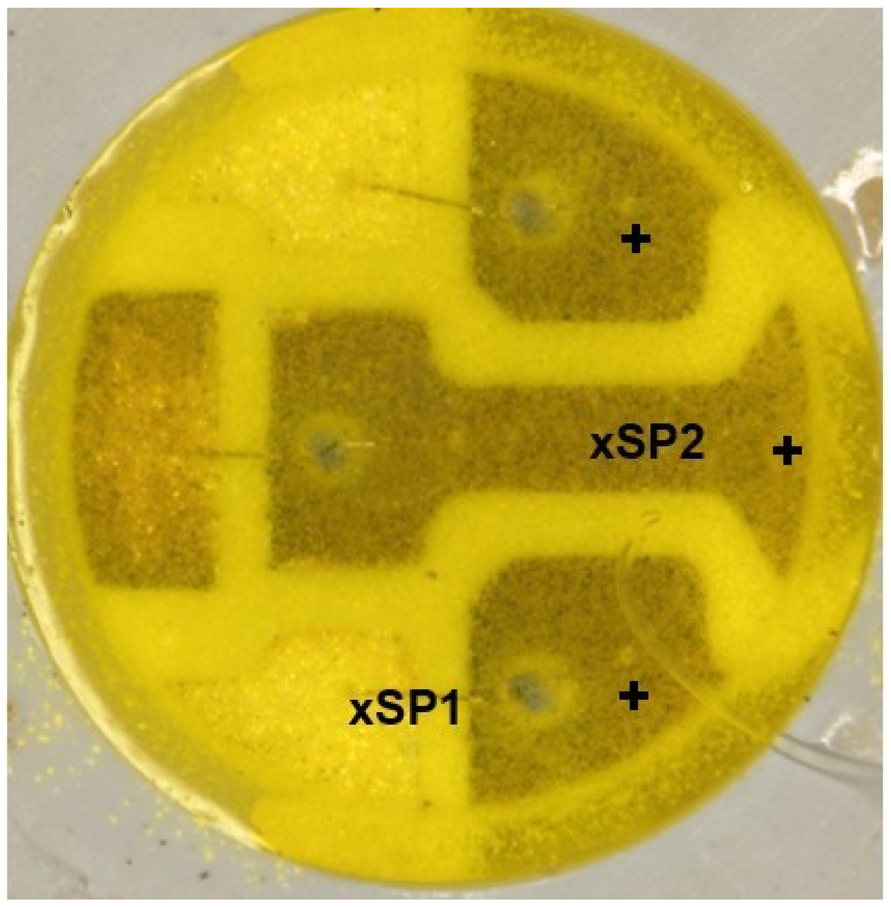
| Atomic Percent (%) | C | O | Si | Ti | Fe | Ni | Cu | Ag |
|---|---|---|---|---|---|---|---|---|
| LED SP1 | 8.96 | 17.40 | 1.76 | 2.34 | 2.66 | 10.68 | 9.36 | 46.85 |
| LED SP2 | 9.07 | 33.63 | 1.97 | 2.78 | 1.73 | 8.17 | 7.30 | 35.34 |
Disclaimer/Publisher’s Note: The statements, opinions and data contained in all publications are solely those of the individual author(s) and contributor(s) and not of MDPI and/or the editor(s). MDPI and/or the editor(s) disclaim responsibility for any injury to people or property resulting from any ideas, methods, instructions or products referred to in the content. |
© 2024 by the authors. Licensee MDPI, Basel, Switzerland. This article is an open access article distributed under the terms and conditions of the Creative Commons Attribution (CC BY) license (https://creativecommons.org/licenses/by/4.0/).
Share and Cite
Harsanyi, G.; Poppe, A.; Hegedüs, J.; Hantos, G.; Bojta, P.; Kovacs, R. Climatically Accelerated Material Processes Determining the Long-Term Reliability of Light-Emitting Diodes. Materials 2024, 17, 1643. https://doi.org/10.3390/ma17071643
Harsanyi G, Poppe A, Hegedüs J, Hantos G, Bojta P, Kovacs R. Climatically Accelerated Material Processes Determining the Long-Term Reliability of Light-Emitting Diodes. Materials. 2024; 17(7):1643. https://doi.org/10.3390/ma17071643
Chicago/Turabian StyleHarsanyi, Gabor, Andras Poppe, Janos Hegedüs, Gusztav Hantos, Peter Bojta, and Robert Kovacs. 2024. "Climatically Accelerated Material Processes Determining the Long-Term Reliability of Light-Emitting Diodes" Materials 17, no. 7: 1643. https://doi.org/10.3390/ma17071643
APA StyleHarsanyi, G., Poppe, A., Hegedüs, J., Hantos, G., Bojta, P., & Kovacs, R. (2024). Climatically Accelerated Material Processes Determining the Long-Term Reliability of Light-Emitting Diodes. Materials, 17(7), 1643. https://doi.org/10.3390/ma17071643