
Vaporization Phase Transition in Cryogenic Liquid Oxygen Sealing Film on Spiral Groove Faces

Abstract
1. Introduction
2. Model Development
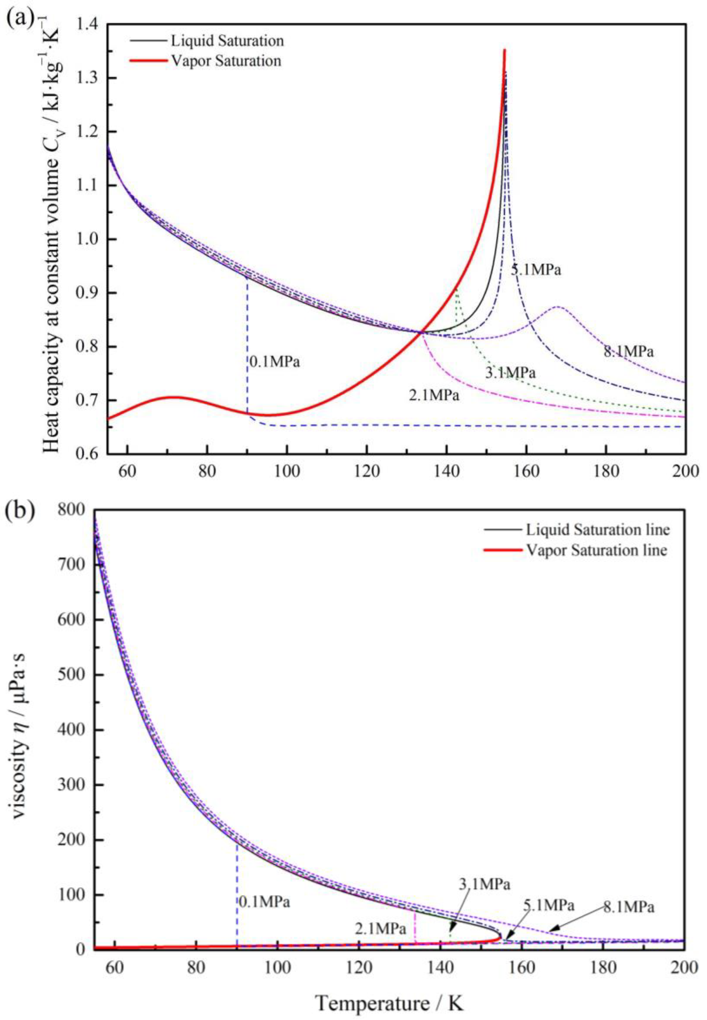
2.1. Fluid Properties
2.2. Control Equations
2.3. Boundary Conditions
2.4. Numerical Method and Verification
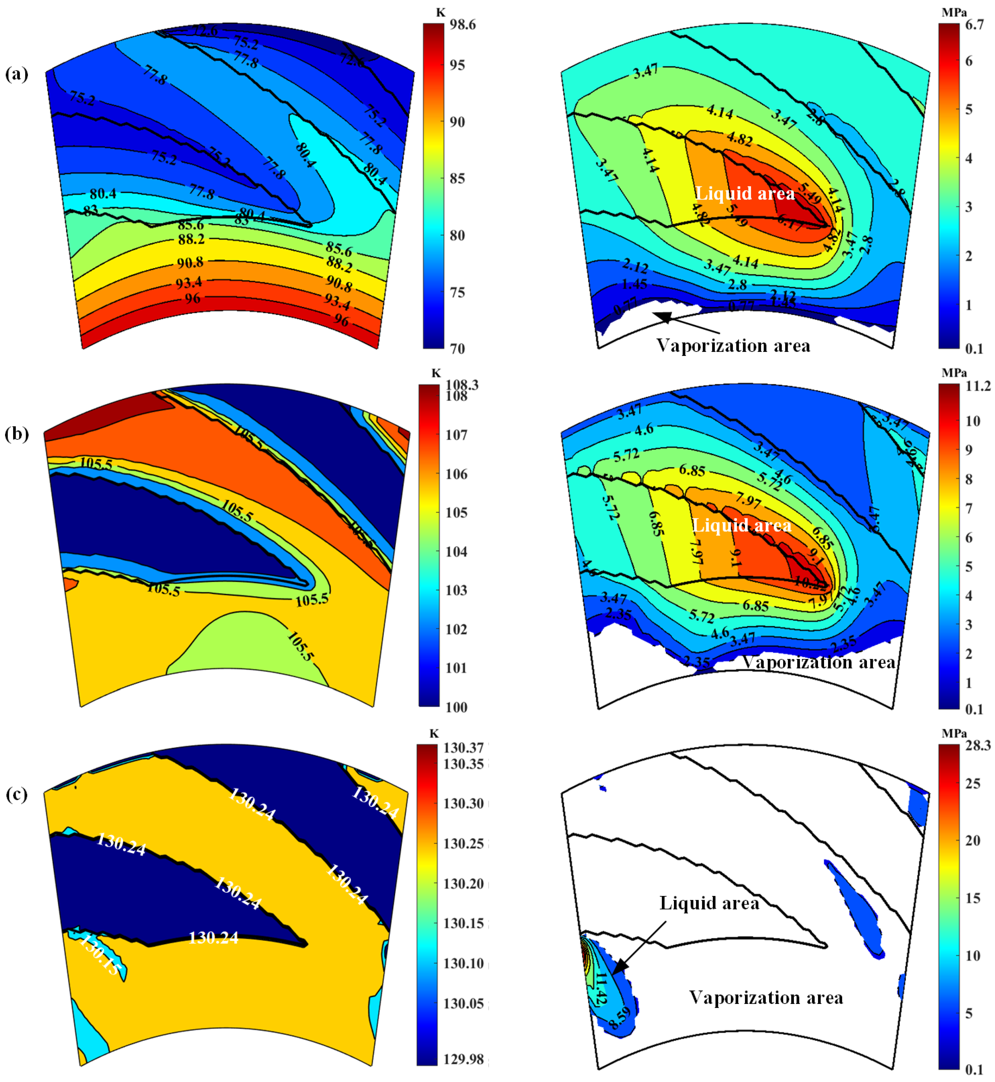
3. Phase Transform Characteristics on Groove Faces
4. Sealing Performance
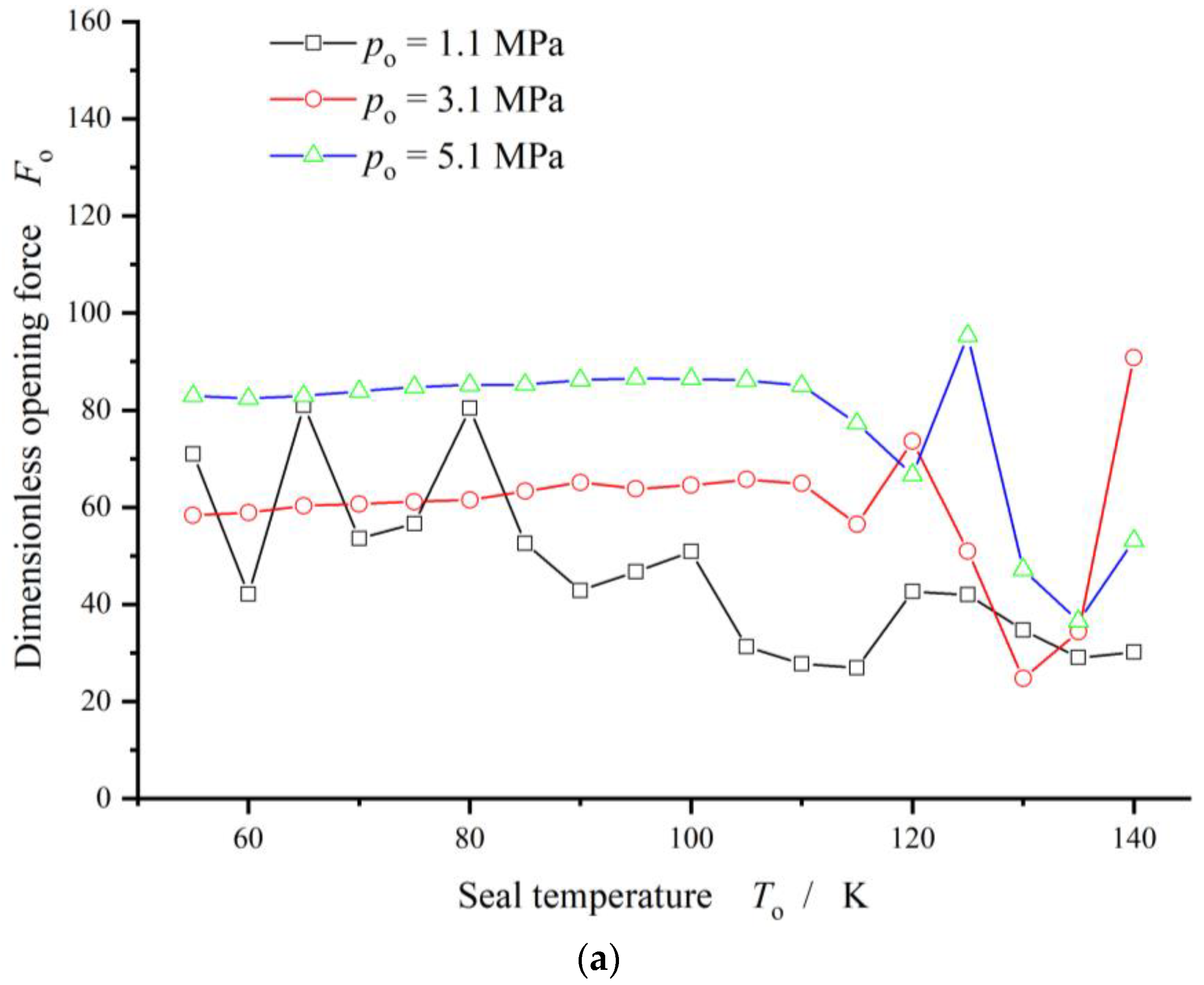
4.1. Seal Pressure
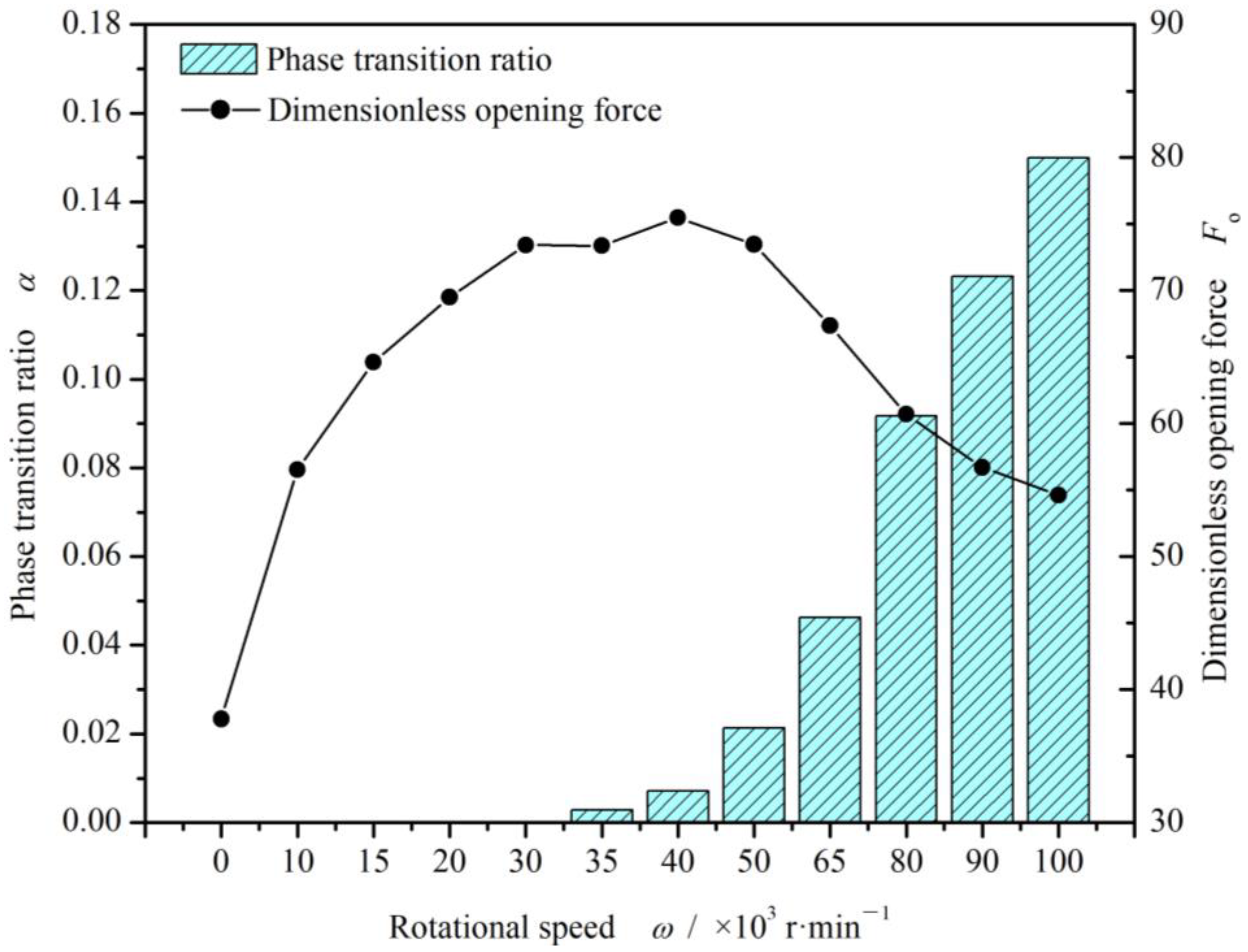
4.2. Rotational Speed
4.3. Seal Clearance
5. Conclusions
- (a)
- A numerical model based on the saturated vapor pressure is established to investigate the vaporization phase transition property of liquid oxygen sealing film, with consideration of heat transfer as well as face distortions. Distributions of vaporization phase transition for cryogenic liquid oxygen are obtained in spiral groove face seals.
- (b)
- Spiral grooves on gas face seals make film temperature distribution and vaporization distribution more uniform at groove region. Meanwhile, with increase in seal temperature and decrease in seal pressure, the vaporization area extends from the low-pressure side to the grooves are, and the vaporization rate increases rapidly.
- (c)
- For cryogenic liquid oxygen spiral groove face seals, vaporization brings drastic fluctuation and non-monotonic change in opening force. With the increase in seal temperature from 55 K to 140 K, the opening force fluctuates violently, and the fluctuation range is more than 50%, showing obvious instability. There is a range of pressure and temperature values, the seal can be stable operation.
Author Contributions
Funding
Institutional Review Board Statement
Informed Consent Statement
Data Availability Statement
Conflicts of Interest
References
- Orcutt, F.K. An Investigation of the operation and failure of mechanical face seals. ASME J. Lubr. Technol. 1969, 91, 713–725. [Google Scholar] [CrossRef]
- Lymer, A. An Engineering Approach to the Selection and Application of Mechanical Seals. In Proceedings of the Fourth International Conference on Fluid Sealing, Philadelphia, PA, USA, 6–9 May 1969; pp. 239–246. [Google Scholar]
- Nau, B.S. Research in Mechanical Seals. Proc. Inst. Mech. Eng. Part C Mech. Eng. Sci. 1990, 204, 349–376. [Google Scholar] [CrossRef]
- Rhodes, D.B.; Hill, R.C.; Wensel, R.G. Reactor Coolant Pump Shaft Seal Stability during Station Blackout; US Nuclear Regulatory Commission (NRC): Washington, DC, USA, 1987. [CrossRef]
- Csomor, A.; Sutton, R. Small, High-Pressure Liquid Oxygen Turbopump; No. R76-178; National Aeronautics and Space Administration: Washinton, DC, USA, 1977.
- Burcham, R. Liquid Rocket Engine Turbopump Rotating-Shaft Seals; National Aeronautics and Space Administration: Washinton, DC, USA, 1978.
- Nosaka, M.; Kato, T. Cryogenic tribology in high-speed bearings and shaft seals of rocket turbopumps. In Tribology—Fundamentals and Advancements; Jurgen, G., Ed.; IN TECH d.o.o: Rijeka, Croatia, 2013; pp. 109–153. [Google Scholar]
- Singh, N. The Hydrodynamic Design and Analysis of a Liquid Oxygen Pump Impeller for a Rocket Engine. Ph.D. Dissertation, University of KwaZulu-Natal, Durban, South Africa, 2018. [Google Scholar]
- Shapiro, W.; Walowit, J.; Jones, H.F. Analysis of spiral-groove face seals for liquid oxygen. ASLE Trans. 1984, 27, 177–188. [Google Scholar] [CrossRef]
- Zhang, G.; Chen, G.; Zhao, W.; Yan, X.; Zhang, Y. An experimental test on a cryogenic high-speed hydrodynamic non-contact mechanical seal. Tribol. Lett. 2017, 65, 80. [Google Scholar] [CrossRef]
- Hughes, W.F.; Winowich, N.S.; Birchak, M.J.; Kennedy, W.C. Phase change in liquid face seals. ASME J. Lubr. Technol. 1978, 100, 74–80. [Google Scholar] [CrossRef]
- Hughes, W.F.; Chao, N.H. Phase change in liquid face seals (II): Isothermal and adiabatic bounds with real fluid. J. Lubr. Technol. 1980, 102, 350–359. [Google Scholar] [CrossRef]
- Yasuna, J.A.; Hughes, W.F. A continuouse boiling model for face seals. J. Tribol. Trans. ASME 1990, 112, 266–274. [Google Scholar] [CrossRef]
- Etsion, I.; Pascovici, M.D. Phase change in a misaligned mechanical face seal. ASME J. Tribol. 1996, 118, 109–115. [Google Scholar] [CrossRef]
- Etsion, I.; Pascovici, M.D.; Burstein, L. The boiling interface in a misaligned two-phase mechanical seal. J. Tribol. 1997, 119, 265–271. [Google Scholar] [CrossRef]
- Ruan, B.; Salant, R.F.; Green, I. A mixed lubrication model of liquid/gas mechanical face seals. Tribol. Trans. 1997, 40, 647–657. [Google Scholar] [CrossRef]
- Rosenkranz, A.; Costa, H.L.; Profito, F.; Gachot, C.; Medina, S.; Dini, D. Influence of surface texturing on hydrodynamic friction in plane converging bearings—An experimental and numerical approach. Tribol. Int. 2019, 134, 190–204. [Google Scholar] [CrossRef]
- Rosenkranz, A.; Grutzmacher, P.G.; Gachot, C.; Costa, H.L. Surface texturing in machine elements—A critical discussion for rolling and sliding contacts. Adv. Eng. Mater. 2019, 21, 20. [Google Scholar] [CrossRef]
- Profito, F.J.; Giacopini, M.; Zachariadis, D.C.; Dini, D. A general finite volume method for the solution of the Reynolds lubrication equation with a Mass-Conserving cavitation model. Tribol. Lett. 2015, 60, 18. [Google Scholar] [CrossRef]
- Zhang, S.; Bogy, D.B. A heat transfer model for thermal fluctuations in a thin slider/disk air bearing. Int. J. Heat Mass Transf. 1999, 42, 1791–1800. [Google Scholar] [CrossRef]
- Meseguer, J.; Pérez-Grande, I.; Sanz-Andrés, A. Mechanical Interfaces. In Spacecraft Thermal Control; Elsevier: Amsterdam, The Netherlands, 2012; pp. 157–173. [Google Scholar]
- Bai, S.X. Thermoelastohydrodynamic gas lubrication of spiral-groove face seals: Modeling and analysis of vapor condensation. STLE Tribol. Trans. 2017, 60, 719–728. [Google Scholar] [CrossRef]
- Blasiak, S.; Kundera, C. A Numerical Analysis of the Grooved Surface Effects on the Thermal Behavior of a Non-Contacting Face Seal. Procedia Eng. 2012, 39, 315–326. [Google Scholar] [CrossRef][Green Version]
- Bai, S.; Li, K.; Yang, J.; Bao, S.; Ma, C. Thermo-hydrodynamic lubricating behaviors of upstream liquid face seals with ellipse dimples. Materials 2023, 16, 3248. [Google Scholar] [CrossRef] [PubMed]
- Bai, S.X.; Song, Y.S.; Yang, J. Elastic deformation of liquid spiral groove face seals operating at high speeds and low pressure. Int. J. Mech. Sci. 2022, 226, 107397. [Google Scholar] [CrossRef]
- Cryogenic Properties of Materials, NIST Cryogenic Technologies Group. Available online: www.cryogenics.nist.gov (accessed on 12 November 2023).
- Fairuz, Z.M.; Jahn, I. The influence of real gas effects on the performance of supercritical CO2 dry gas seals. Tribol. Int. 2016, 102, 333–347. [Google Scholar] [CrossRef]
- Bai, S.X.; Wen, S.Z. Gas Thermohydrodynamic Lubrication and Seals, 1st ed.; Elsevier Academic Press: Cambridge, MA, USA, 2019. [Google Scholar]


| Item | Symbol | Dimensions and Data |
|---|---|---|
| Inside radius | ri | 24 mm |
| Outside radius | ro | 30 mm |
| Spiral radius | rp | 26.5 mm |
| Ring thickness | h1, h2 | 15 mm |
| Groove depth | hd | 5 μm |
| Groove number | N | 12 |
| Spiral angle | β | 16° |
| Characteristics | Carbon | Steel |
|---|---|---|
| Density (kg m−3) | 1800 | 7930 |
| Young’s modulus (GPa) | 25 | 204 |
| Poisson’s coefficient | 0.2 | 0.3 |
| Specific heat capacity (J Kg−1K−1) | 710 | 500 |
| Thermal conductivity (W m−1 K−1) | 129 | 17 |
| Linear thermal expansion coefficient (10−6 °C) | 4.0 | 16.0 |
Disclaimer/Publisher’s Note: The statements, opinions and data contained in all publications are solely those of the individual author(s) and contributor(s) and not of MDPI and/or the editor(s). MDPI and/or the editor(s) disclaim responsibility for any injury to people or property resulting from any ideas, methods, instructions or products referred to in the content. |
© 2024 by the authors. Licensee MDPI, Basel, Switzerland. This article is an open access article distributed under the terms and conditions of the Creative Commons Attribution (CC BY) license (https://creativecommons.org/licenses/by/4.0/).
Share and Cite
Chen, J.; Ma, C.; Bai, S.; Yang, J. Vaporization Phase Transition in Cryogenic Liquid Oxygen Sealing Film on Spiral Groove Faces. Materials 2024, 17, 1443. https://doi.org/10.3390/ma17061443
Chen J, Ma C, Bai S, Yang J. Vaporization Phase Transition in Cryogenic Liquid Oxygen Sealing Film on Spiral Groove Faces. Materials. 2024; 17(6):1443. https://doi.org/10.3390/ma17061443
Chicago/Turabian StyleChen, Junjie, Chunhong Ma, Shaoxian Bai, and Jing Yang. 2024. "Vaporization Phase Transition in Cryogenic Liquid Oxygen Sealing Film on Spiral Groove Faces" Materials 17, no. 6: 1443. https://doi.org/10.3390/ma17061443
APA StyleChen, J., Ma, C., Bai, S., & Yang, J. (2024). Vaporization Phase Transition in Cryogenic Liquid Oxygen Sealing Film on Spiral Groove Faces. Materials, 17(6), 1443. https://doi.org/10.3390/ma17061443